OD off warning SUZUKI GRAND VITARA 2001 2.G Owners Manual
[x] Cancel search | Manufacturer: SUZUKI, Model Year: 2001, Model line: GRAND VITARA, Model: SUZUKI GRAND VITARA 2001 2.GPages: 656, PDF Size: 14.31 MB
Page 8 of 656
GENERAL INFORMATION 0A-3
Servicing and handling
WARNING:
Many of service procedures require disconnection of
“AIR BAG” fuse and all air bag (inflator) module(s) from
initiator circuit to avoid an accidental deployment.
Driver and Passenger Air Bag (Inflator) Modules
For handling and storage of a live air bag (inflator)
module, select a place where the ambient temperature
below 65°C (150°F), without high humidity and away
from electric noise.
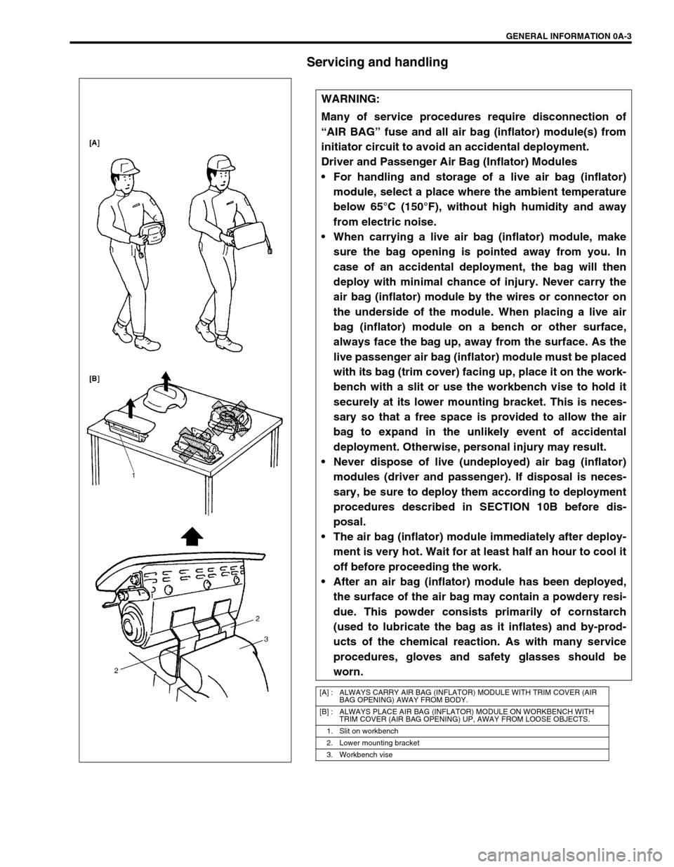
When carrying a live air bag (inflator) module, make
sure the bag opening is pointed away from you. In
case of an accidental deployment, the bag will then
deploy with minimal chance of injury. Never carry the
air bag (inflator) module by the wires or connector on
the underside of the module. When placing a live air
bag (inflator) module on a bench or other surface,
always face the bag up, away from the surface. As the
live passenger air bag (inflator) module must be placed
with its bag (trim cover) facing up, place it on the work-
bench with a slit or use the workbench vise to hold it
securely at its lower mounting bracket. This is neces-
sary so that a free space is provided to allow the air
bag to expand in the unlikely event of accidental
deployment. Otherwise, personal injury may result.
Never dispose of live (undeployed) air bag (inflator)
modules (driver and passenger). If disposal is neces-
sary, be sure to deploy them according to deployment
procedures described in SECTION 10B before dis-
posal.
The air bag (inflator) module immediately after deploy-
ment is very hot. Wait for at least half an hour to cool it
off before proceeding the work.
After an air bag (inflator) module has been deployed,
the surface of the air bag may contain a powdery resi-
due. This powder consists primarily of cornstarch
(used to lubricate the bag as it inflates) and by-prod-
ucts of the chemical reaction. As with many service
procedures, gloves and safety glasses should be
worn.
[A] : ALWAYS CARRY AIR BAG (INFLATOR) MODULE WITH TRIM COVER (AIR
BAG OPENING) AWAY FROM BODY.
[B] : ALWAYS PLACE AIR BAG (INFLATOR) MODULE ON WORKBENCH WITH
TRIM COVER (AIR BAG OPENING) UP, AWAY FROM LOOSE OBJECTS.
1. Slit on workbench
2. Lower mounting bracket
3. Workbench vise
Page 9 of 656
0A-4 GENERAL INFORMATION
WARNING:
SDM
During service procedures, be very careful when handling a Sensing and Diagnostic Module (SDM).
Never strike or jar the SDM.
Never power up the air bag system when the SDM is not rigidly attached to the vehicle. All SDM and
mounting bracket fasteners must be carefully torqued and the arrow must be pointing toward the
front of the vehicle to ensure proper operation of the air bag system.
The SDM could be activated when powered while not rigidly attached to the vehicle which could
cause deployment and result in personal injury.
WARNING:
Driver and Passenger Seat Belt Pretensioners
For handling and storage of a live seat belt preten-
sioner, select a place where the ambient temperature
below 65°C (150°F), without high humidity and away
from electric noise.
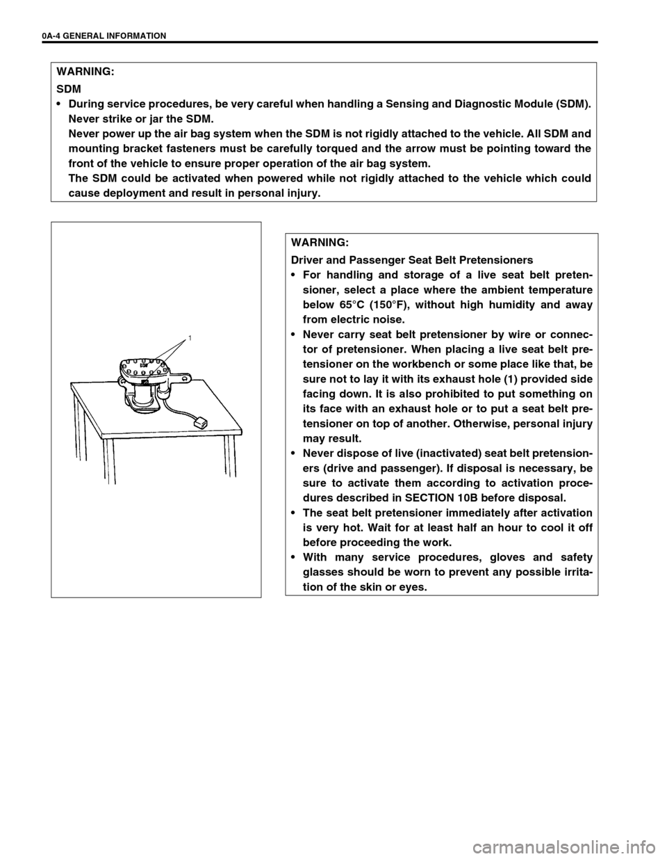
Never carry seat belt pretensioner by wire or connec-
tor of pretensioner. When placing a live seat belt pre-
tensioner on the workbench or some place like that, be
sure not to lay it with its exhaust hole (1) provided side
facing down. It is also prohibited to put something on
its face with an exhaust hole or to put a seat belt pre-
tensioner on top of another. Otherwise, personal injury
may result.
Never dispose of live (inactivated) seat belt pretension-
ers (drive and passenger). If disposal is necessary, be
sure to activate them according to activation proce-
dures described in SECTION 10B before disposal.
The seat belt pretensioner immediately after activation
is very hot. Wait for at least half an hour to cool it off
before proceeding the work.
With many service procedures, gloves and safety
glasses should be worn to prevent any possible irrita-
tion of the skin or eyes.
Page 10 of 656
GENERAL INFORMATION 0A-5
CAUTION:
Even when the accident was light enough not to cause air bags to activate, be sure to inspect sys-
tem parts and other related parts according to instructions under “REPAIR AND INSPECTION
REQUIRED AFTER AN ACCIDENT” in SECTION 10B.
When servicing parts other than air bag system, if shocks may be applied to air bag system compo-
nent parts, remove those parts beforehand.
When handling the air bag (inflator) modules (driver and passenger), forward sensors or SDM, be
careful not to drop it or apply an impact to it. If an excessive impact was applied (e.g., dropped from
a height of 91.4 cm (3 feet) or more), never attempt disassembly or repair but replace it with a new
one.
When grease, cleaning agent, oil, water, etc. has got onto air bag (inflator) modules (driver and pas-
senger), wipe off immediately with a dry cloth.
Air bag wire harness can be identified easily as it is covered with a yellow protection tube. Be very
careful when handling it.
When an open in air bag wire harness, damaged wire harness, connector or terminal is found,
replace wire harness, connectors and terminals as an assembly.
Do not apply power to the air bag system unless all components are connected or a diagnostic
chart requests it, as this will set a diagnostic trouble code.
Never use air bag system component parts from another vehicle.
When using electric welding, be sure to temporarily disable air bag system referring to “DIS-
ABLING AIR BAG SYSTEM” in SECTION 10B.
Never expose air bag system component parts directly to hot air (drying or baking the vehicle after
painting) or flames.
WARNING/CAUTION labels are attached on each part of air bag system components. Be sure to fol-
low the instructions.
After vehicle is completely repaired, perform “AIR BAG DIAGNOSTIC SYSTEM CHECK” in SEC-
TION 10B.
Page 107 of 656
5-2 BRAKES
Diagnosis
Diagnosis Table
For the item not found in this column, refer to the same item of the same section in the service manual men-
tioned in the FOREWORD of this manual.
Condition Possible Cause Correction
Brake warning light
turns on after engine
startParking brake applied Release parking brake and check
that brake warning light turns off.
Insufficient amount of brake fluid Add brake fluid.
Brake fluid leaking from brake line Investigate leaky point, correct it
and add brake fluid.
Brake warning light circuit faulty Repair circuit.
Malfunctioning EBD system Check system referring to “DIAG-
NOSIS” of Section 5E2.
ABS warning light
does not turn on for 2
– 3 sec. after ignition
switch has turned ON.Bulb burnt out Replace bulb.
ABS warning light circuit open (including check
relay)Check system referring to “DIAG-
NOSIS” in Section 5E2.
ABS warning light
remains on after igni-
tion switch has turned
on for 2 – 3 sec.Malfunctioning ABS Check system referring to “DIAG-
NOSIS” in Section 5E2.
Page 109 of 656
5A-2 BRAKES PIPE/HOSE/MASTER CYLINDER
General Description
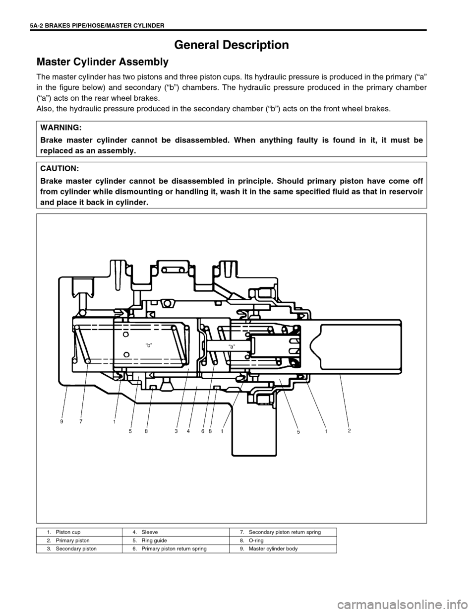
Master Cylinder Assembly
The master cylinder has two pistons and three piston cups. Its hydraulic pressure is produced in the primary (“a”
in the figure below) and secondary (“b”) chambers. The hydraulic pressure produced in the primary chamber
(“a”) acts on the rear wheel brakes.
Also, the hydraulic pressure produced in the secondary chamber (“b”) acts on the front wheel brakes.
WARNING:
Brake master cylinder cannot be disassembled. When anything faulty is found in it, it must be
replaced as an assembly.
CAUTION:
Brake master cylinder cannot be disassembled in principle. Should primary piston have come off
from cylinder while dismounting or handling it, wash it in the same specified fluid as that in reservoir
and place it back in cylinder.
1. Piston cup 4. Sleeve 7. Secondary piston return spring
2. Primary piston 5. Ring guide 8. O-ring
3. Secondary piston 6. Primary piston return spring 9. Master cylinder body
Page 129 of 656
5E2-4 ANTILOCK BRAKE SYSTEM (ABS)
ABS Hydraulic Unit/control Module Assembly
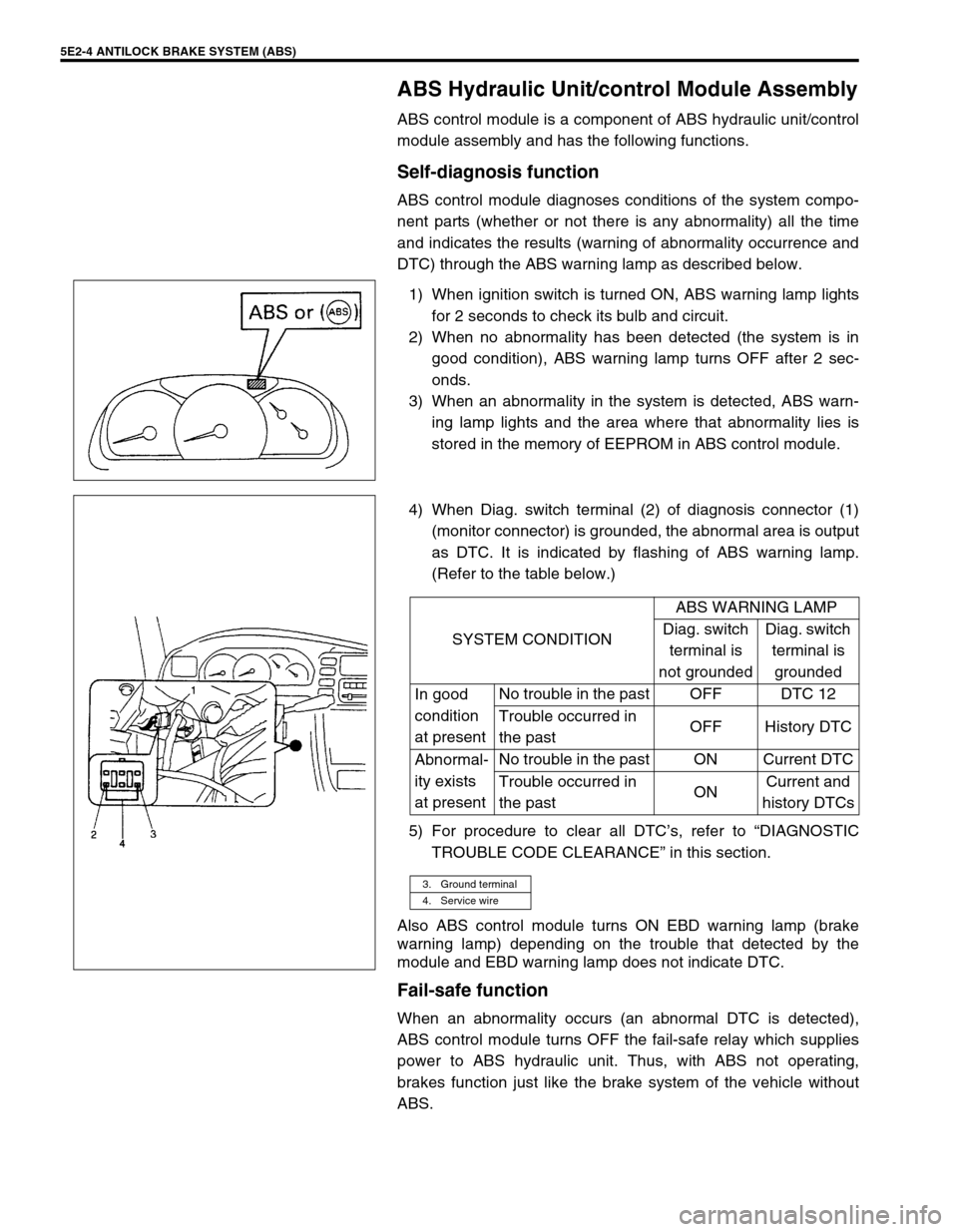
ABS control module is a component of ABS hydraulic unit/control
module assembly and has the following functions.
Self-diagnosis function
ABS control module diagnoses conditions of the system compo-
nent parts (whether or not there is any abnormality) all the time
and indicates the results (warning of abnormality occurrence and
DTC) through the ABS warning lamp as described below.
1) When ignition switch is turned ON, ABS warning lamp lights
for 2 seconds to check its bulb and circuit.
2) When no abnormality has been detected (the system is in
good condition), ABS warning lamp turns OFF after 2 sec-
onds.
3) When an abnormality in the system is detected, ABS warn-
ing lamp lights and the area where that abnormality lies is
stored in the memory of EEPROM in ABS control module.
4) When Diag. switch terminal (2) of diagnosis connector (1)
(monitor connector) is grounded, the abnormal area is output
as DTC. It is indicated by flashing of ABS warning lamp.
(Refer to the table below.)
5) For procedure to clear all DTC’s, refer to “DIAGNOSTIC
TROUBLE CODE CLEARANCE” in this section.
Also ABS control module turns ON EBD warning lamp (brake
warning lamp) depending on the trouble that detected by the
module and EBD warning lamp does not indicate DTC.
Fail-safe function
When an abnormality occurs (an abnormal DTC is detected),
ABS control module turns OFF the fail-safe relay which supplies
power to ABS hydraulic unit. Thus, with ABS not operating,
brakes function just like the brake system of the vehicle without
ABS.
SYSTEM CONDITIONABS WARNING LAMP
Diag. switch
terminal is
not groundedDiag. switch
terminal is
grounded
In good
condition
at presentNo trouble in the past OFF DTC 12
Trouble occurred in
the pastOFF History DTC
Abnormal-
ity exists
at presentNo trouble in the past ON Current DTC
Trouble occurred in
the pastONCurrent and
history DTCs
3. Ground terminal
4. Service wire
Page 134 of 656
ANTILOCK BRAKE SYSTEM (ABS) 5E2-9
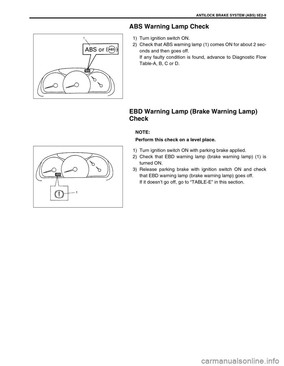
ABS Warning Lamp Check
1) Turn ignition switch ON.
2) Check that ABS warning lamp (1) comes ON for about 2 sec-
onds and then goes off.
If any faulty condition is found, advance to Diagnostic Flow
Table-A, B, C or D.
EBD Warning Lamp (Brake Warning Lamp)
Check
1) Turn ignition switch ON with parking brake applied.
2) Check that EBD warning lamp (brake warning lamp) (1) is
turned ON.
3) Release parking brake with ignition switch ON and check
that EBD warning lamp (brake warning lamp) goes off.
If it doesn’t go off, go to “TABLE-E” in this section.
NOTE:
Perform this check on a level place.
Page 135 of 656
5E2-10 ANTILOCK BRAKE SYSTEM (ABS)
Diagnostic Trouble Code (DTC) Check (Using
ABS Warning Lamp)
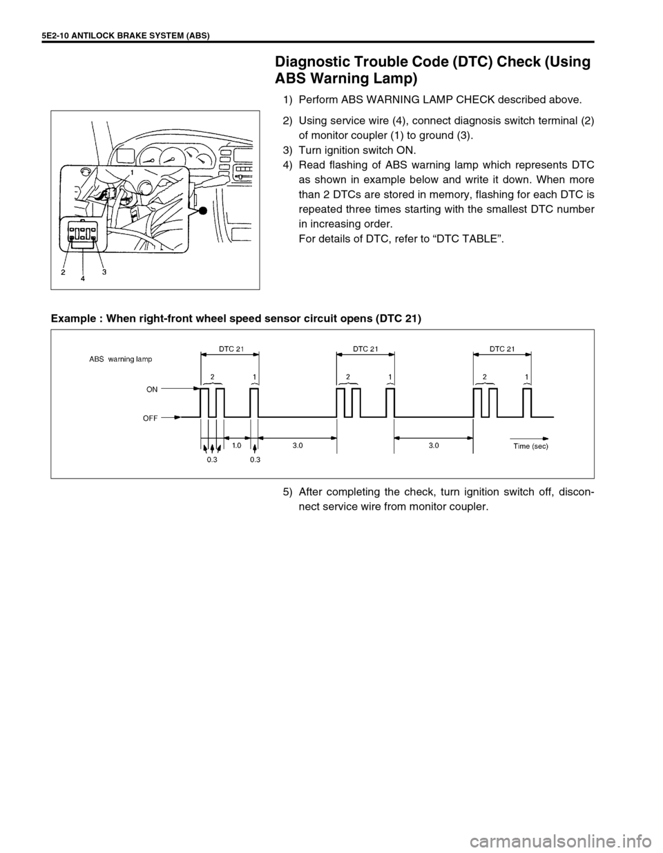
1) Perform ABS WARNING LAMP CHECK described above.
2) Using service wire (4), connect diagnosis switch terminal (2)
of monitor coupler (1) to ground (3).
3) Turn ignition switch ON.
4) Read flashing of ABS warning lamp which represents DTC
as shown in example below and write it down. When more
than 2 DTCs are stored in memory, flashing for each DTC is
repeated three times starting with the smallest DTC number
in increasing order.
For details of DTC, refer to “DTC TABLE”.
Example : When right-front wheel speed sensor circuit opens (DTC 21)
5) After completing the check, turn ignition switch off, discon-
nect service wire from monitor coupler.
Page 136 of 656
ANTILOCK BRAKE SYSTEM (ABS) 5E2-11
Diagnostic Trouble Code (DTC) Check (Using
SUZUKI Scan Tool)
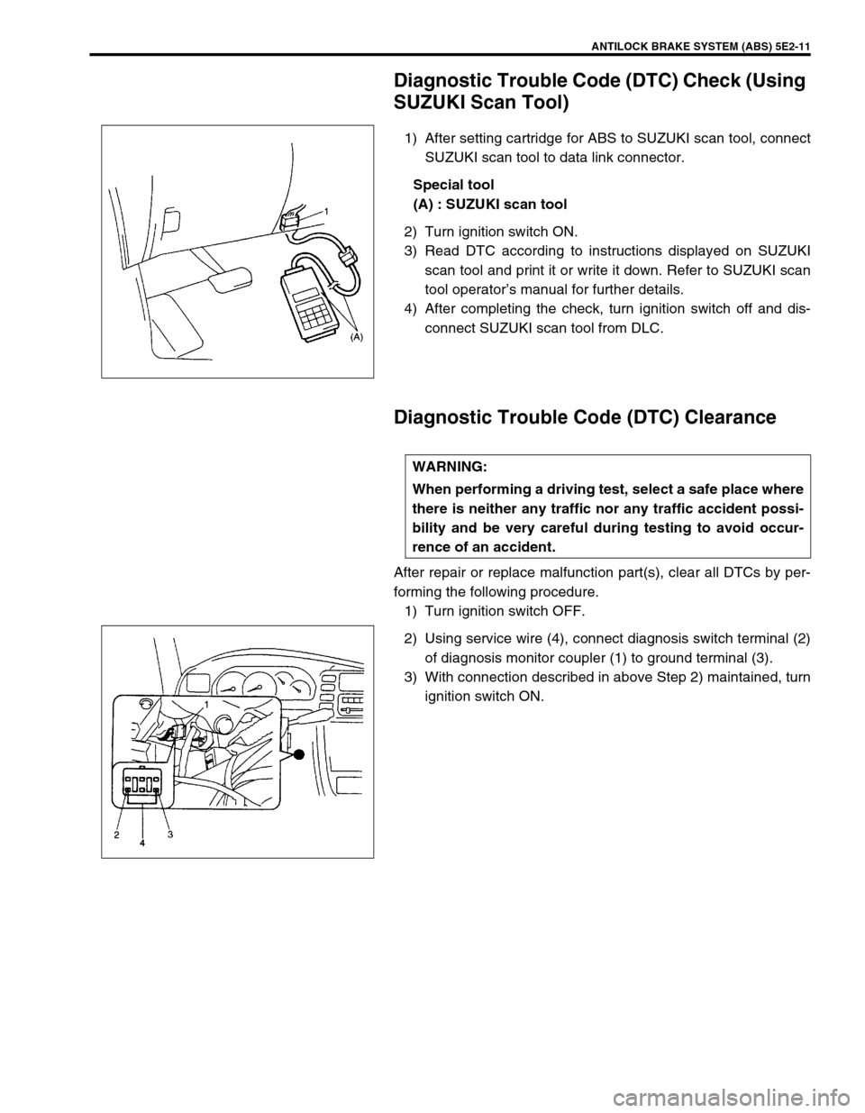
1) After setting cartridge for ABS to SUZUKI scan tool, connect
SUZUKI scan tool to data link connector.
Special tool
(A) : SUZUKI scan tool
2) Turn ignition switch ON.
3) Read DTC according to instructions displayed on SUZUKI
scan tool and print it or write it down. Refer to SUZUKI scan
tool operator’s manual for further details.
4) After completing the check, turn ignition switch off and dis-
connect SUZUKI scan tool from DLC.
Diagnostic Trouble Code (DTC) Clearance
After repair or replace malfunction part(s), clear all DTCs by per-
forming the following procedure.
1) Turn ignition switch OFF.
2) Using service wire (4), connect diagnosis switch terminal (2)
of diagnosis monitor coupler (1) to ground terminal (3).
3) With connection described in above Step 2) maintained, turn
ignition switch ON.
WARNING:
When performing a driving test, select a safe place where
there is neither any traffic nor any traffic accident possi-
bility and be very careful during testing to avoid occur-
rence of an accident.
Page 137 of 656
5E2-12 ANTILOCK BRAKE SYSTEM (ABS)
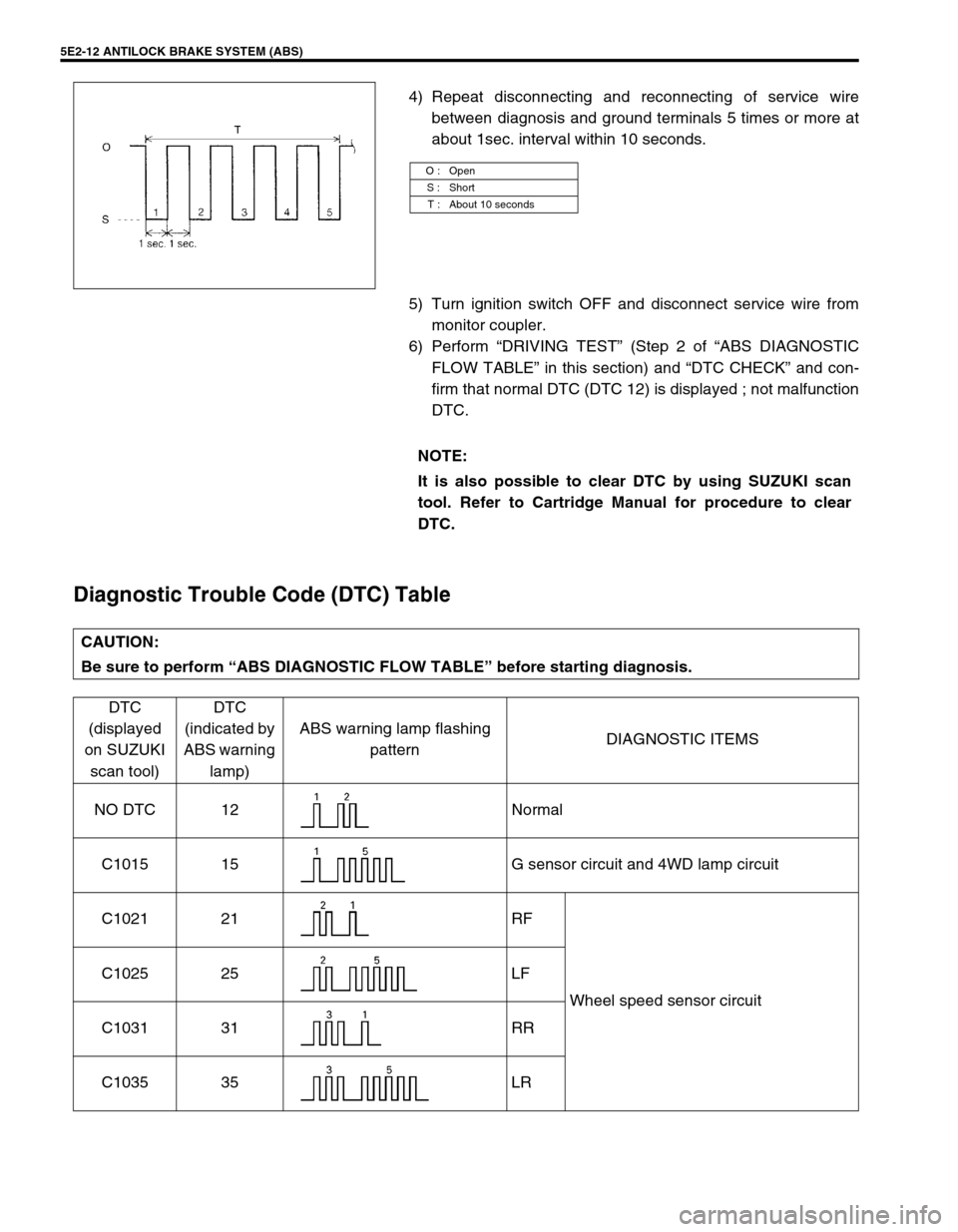
4) Repeat disconnecting and reconnecting of service wire
between diagnosis and ground terminals 5 times or more at
about 1sec. interval within 10 seconds.
5) Turn ignition switch OFF and disconnect service wire from
monitor coupler.
6) Perform “DRIVING TEST” (Step 2 of “ABS DIAGNOSTIC
FLOW TABLE” in this section) and “DTC CHECK” and con-
firm that normal DTC (DTC 12) is displayed ; not malfunction
DTC.
Diagnostic Trouble Code (DTC) Table
O : Open
S : Short
T : About 10 seconds
NOTE:
It is also possible to clear DTC by using SUZUKI scan
tool. Refer to Cartridge Manual for procedure to clear
DTC.
CAUTION:
Be sure to perform “ABS DIAGNOSTIC FLOW TABLE” before starting diagnosis.
DTC
(displayed
on SUZUKI
scan tool)DTC
(indicated by
ABS warning
lamp)ABS warning lamp flashing
patternDIAGNOSTIC ITEMS
NO DTC 12 Normal
C1015 15 G sensor circuit and 4WD lamp circuit
C1021 21 RF
Wheel speed sensor circuit C1025 25 LF
C1031 31 RR
C1035 35 LR