Pressure SUZUKI GRAND VITARA 2001 2.G Owners Manual
[x] Cancel search | Manufacturer: SUZUKI, Model Year: 2001, Model line: GRAND VITARA, Model: SUZUKI GRAND VITARA 2001 2.GPages: 656, PDF Size: 14.31 MB
Page 19 of 656
0B-6 MAINTENANCE AND LUBRICATION
POWER STEERING PUMP AND/OR A/C COMPRESSOR
DRIVE BELTS (IF EQUIPPED) INSPECTION
1) Disconnect negative (–) cable at battery.
2) Inspect belt for cracks, cuts, deformation, wear and cleanli-
ness. If any defect exists, replace.
Check belt for tension.
If belt tension is out of above specification, adjust it referring
to Section 1B or 3B1.
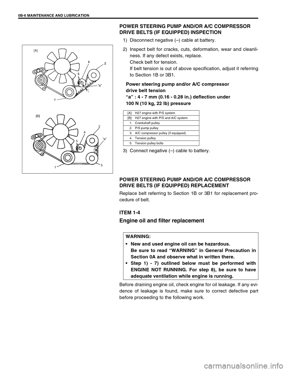
Power steering pump and/or A/C compressor
drive belt tension
“a” : 4 - 7 mm (0.16 - 0.28 in.) deflection under
100 N (10 kg, 22 lb) pressure
3) Connect negative (–) cable to battery.
POWER STEERING PUMP AND/OR A/C COMPRESSOR
DRIVE BELTS (IF EQUIPPED) REPLACEMENT
Replace belt referring to Section 1B or 3B1 for replacement pro-
cedure of belt.
ITEM 1-4
Engine oil and filter replacement
Before draining engine oil, check engine for oil leakage. If any evi-
dence of leakage is found, make sure to correct defective part
before proceeding to the following work.
[A]: H27 engine with P/S system
[B]: H27 engine with P/S and A/C system
1. Crankshaft pulley
2. P/S pump pulley
3. A/C compressor pulley (if equipped)
4. Tension pulley
5. Tension pulley bolts
WARNING:
New and used engine oil can be hazardous.
Be sure to read “WARNING” in General Precaution in
Section 0A and observe what in written there.
Step 1) - 7) outlined below must be performed with
ENGINE NOT RUNNING. For step 8), be sure to have
adequate ventilation while engine is running.
Page 26 of 656
AIR CONDITIONING (OPTIONAL) 1B-1
1B
SECTION 1B
AIR CONDITIONING (OPTIONAL)
CONTENTS
General Description ....................................... 1B-3
Refrigerant Type .......................................... 1B-3
Refrigerant Flow of Air Conditioning System 1B-3
Major Components And Location ................. 1B-4
Diagnosis ........................................................ 1B-6
General ........................................................ 1B-6
Main A/C system (front A/C system) ........ 1B-6
Rear A/C system ...................................... 1B-8
Quickly Checking of Refrigerant Charge
(If Equipped with Sight Glass) ...................... 1B-9
Performance Diagnosis .............................. 1B-10
Performance diagnosis table .................. 1B-12
Detail diagnosis table (at ambient temperature within 30 - 35 °C
(85 - 95 °F)) ............................................ 1B-13
Wiring Circuit.............................................. 1B-14
Inspection of A/C Controller and Its
Circuits ....................................................... 1B-15
Voltage check......................................... 1B-15
Refrigerant Recovery, Evacuation and
Charging ....................................................... 1B-19
Operation Procedure for Charging A/C with
Refrigerant ................................................. 1B-19
Recovery .................................................... 1B-20
Evacuating ................................................. 1B-21
Evacuating procedure ............................ 1B-21
Checking system for pressure leaks ...... 1B-22 WARNING:
For vehicles equipped with Supplemental Restraint (Air Bag) System:
Service on and around the air bag system components or wiring must be performed only by an
authorized SUZUKI dealer. Refer to “Air Bag System Components and Wiring Location View” under
“General Description” in air bag system section in order to confirm whether you are performing ser-
vice on or near the air bag system components or wiring. Please observe all WARNINGS and “Ser-
vice Precautions” under “On-Vehicle Service” in air bag system section before performing service
on or around the air bag system components or wiring. Failure to follow WARNINGS could result in
unintentional activation of the system or could render the system inoperative. Either of these two
conditions may result in severe injury.
Technical service work must be started at least 90 seconds after the ignition switch is turned to the
“LOCK” position and the negative cable is disconnected from the battery. Otherwise, the system
may be activated by reserve energy in the Sensing and Diagnostic Module (SDM).
CAUTION:
The air conditioning system of this vehicle uses refrigerant HFC-134a (R-134a).
None of refrigerant, compressor oil and component parts is interchangeable between two types of
A/C: one using refrigerant CFC-12 (R-12) and the other using refrigerant HFC-134a (R-134a).
Be sure to check which refrigerant is used before any service work including inspection and mainte-
nance. For identification between these two types, refer to “REFRIGERANT TYPE” in this section.
When replenishing or changing refrigerant and compressor oil and when replacing parts, make sure
that the material or the part to be used is appropriate to the A/C installed in the vehicle being serviced.
Use of incorrect one will result in leakage of refrigerant, damage in parts or other faulty condition.
NOTE:
For the descriptions (items) not found in this section, refer to the same section of the Service Man-
ual mentioned in FOREWORD of this manual.
For basic servicing method of the air conditioning system that is not described in this section, refer
to “AIR CONDITIONING BASIC MANUAL (99520-02130)”.
Page 28 of 656
AIR CONDITIONING (OPTIONAL) 1B-3
General Description
Refrigerant Type
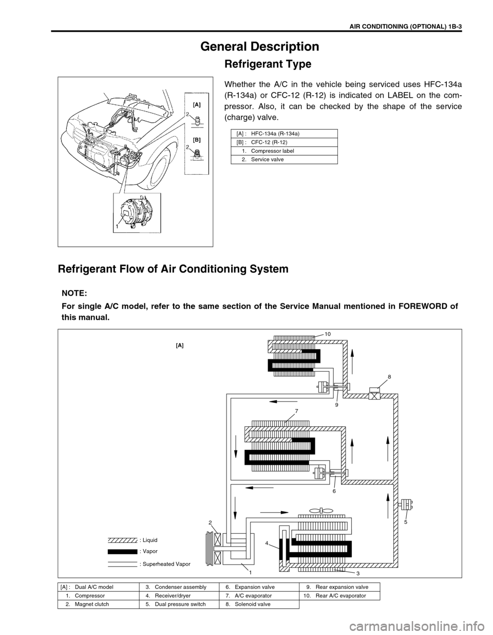
Whether the A/C in the vehicle being serviced uses HFC-134a
(R-134a) or CFC-12 (R-12) is indicated on LABEL on the com-
pressor. Also, it can be checked by the shape of the service
(charge) valve.
Refrigerant Flow of Air Conditioning System
[A] : HFC-134a (R-134a)
[B] : CFC-12 (R-12)
1. Compressor label
2. Service valve
NOTE:
For single A/C model, refer to the same section of the Service Manual mentioned in FOREWORD of
this manual.
[A] : Dual A/C model 3. Condenser assembly 6. Expansion valve 9. Rear expansion valve
1. Compressor 4. Receiver/dryer 7. A/C evaporator 10. Rear A/C evaporator
2. Magnet clutch 5. Dual pressure switch 8. Solenoid valve
[A]10
8
9
5
7
6
3
2
14 : Liquid
: Vapor
: Superheated Vapor
Page 30 of 656
![SUZUKI GRAND VITARA 2001 2.G Owners Manual AIR CONDITIONING (OPTIONAL) 1B-5
[A] : Dual A/C LH steering model 4. Condenser 11. Low pressure charge valve
[B] : Dual A/C RH steering model 5. Sight glass 12. Floor liquid pipe
[C] : Single A/C LH s SUZUKI GRAND VITARA 2001 2.G Owners Manual AIR CONDITIONING (OPTIONAL) 1B-5
[A] : Dual A/C LH steering model 4. Condenser 11. Low pressure charge valve
[B] : Dual A/C RH steering model 5. Sight glass 12. Floor liquid pipe
[C] : Single A/C LH s](/img/20/7584/w960_7584-29.png)
AIR CONDITIONING (OPTIONAL) 1B-5
[A] : Dual A/C LH steering model 4. Condenser 11. Low pressure charge valve
[B] : Dual A/C RH steering model 5. Sight glass 12. Floor liquid pipe
[C] : Single A/C LH steering model 6. Refrigerant (dual) pressure sensor 13. Floor suction pipe
[D] : Single A/C RH steering model 7. Discharge pipe 14. Rear A/C unit
1. Front cooling unit 8. Liquid pipe 15. Rear A/C duct No.1
2. Heater unit 9. Suction pipe 16. Rear A/C duct No.2
3. Compressor 10. High pressure charge valve
[A]
[B]
[C][D]
10
7
9 3 4 6 5 1181
213
12 16
1514
1 2
13
12 16
1514
7
10
5
6
4
38
9 11
1 2
7
10
5
6
4
38
9 11
10
7
9 3 4 6 5 1181
2
Page 31 of 656
1B-6 AIR CONDITIONING (OPTIONAL)
Diagnosis
General
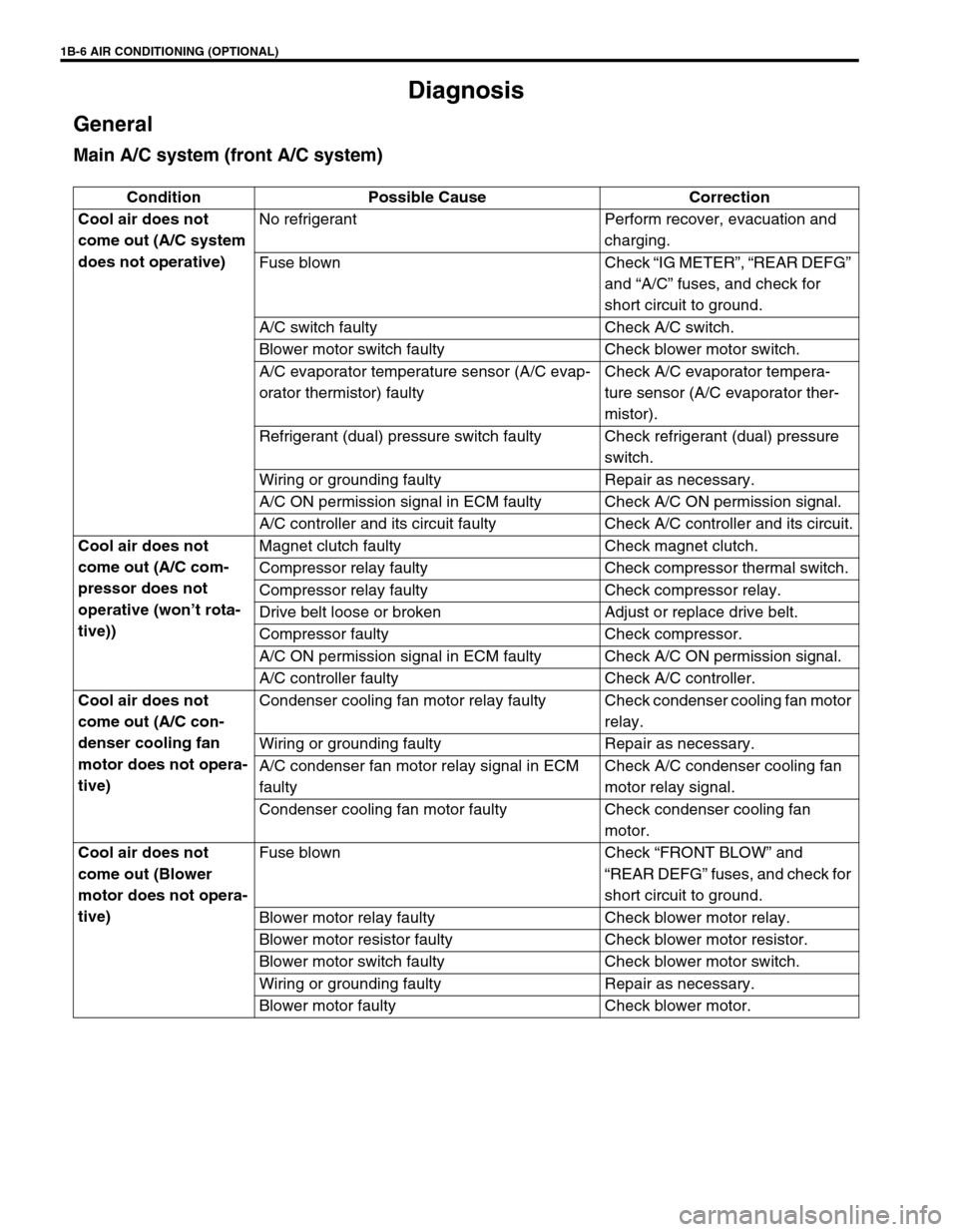
Main A/C system (front A/C system)
Condition Possible Cause Correction
Cool air does not
come out (A/C system
does not operative)No refrigerant Perform recover, evacuation and
charging.
Fuse blown Check “IG METER”, “REAR DEFG”
and “A/C” fuses, and check for
short circuit to ground.
A/C switch faulty Check A/C switch.
Blower motor switch faulty Check blower motor switch.
A/C evaporator temperature sensor (A/C evap-
orator thermistor) faultyCheck A/C evaporator tempera-
ture sensor (A/C evaporator ther-
mistor).
Refrigerant (dual) pressure switch faulty Check refrigerant (dual) pressure
switch.
Wiring or grounding faulty Repair as necessary.
A/C ON permission signal in ECM faulty Check A/C ON permission signal.
A/C controller and its circuit faulty Check A/C controller and its circuit.
Cool air does not
come out (A/C com-
pressor does not
operative (won’t rota-
tive))Magnet clutch faulty Check magnet clutch.
Compressor relay faulty Check compressor thermal switch.
Compressor relay faulty Check compressor relay.
Drive belt loose or broken Adjust or replace drive belt.
Compressor faulty Check compressor.
A/C ON permission signal in ECM faulty Check A/C ON permission signal.
A/C controller faulty Check A/C controller.
Cool air does not
come out (A/C con-
denser cooling fan
motor does not opera-
tive)Condenser cooling fan motor relay faulty Check condenser cooling fan motor
relay.
Wiring or grounding faulty Repair as necessary.
A/C condenser fan motor relay signal in ECM
faultyCheck A/C condenser cooling fan
motor relay signal.
Condenser cooling fan motor faulty Check condenser cooling fan
motor.
Cool air does not
come out (Blower
motor does not opera-
tive)Fuse blown Check “FRONT BLOW” and
“REAR DEFG” fuses, and check for
short circuit to ground.
Blower motor relay faulty Check blower motor relay.
Blower motor resistor faulty Check blower motor resistor.
Blower motor switch faulty Check blower motor switch.
Wiring or grounding faulty Repair as necessary.
Blower motor faulty Check blower motor.
Page 35 of 656
1B-10 AIR CONDITIONING (OPTIONAL)
Performance Diagnosis
1) Confirm that vehicle and environmental conditions are as fol-
lows.
Vehicle is not exposed to direct sun.
Ambient temperature is within 15 - 35 °C (59 - 95 °F).
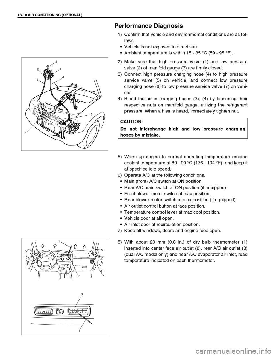
2) Make sure that high pressure valve (1) and low pressure
valve (2) of manifold gauge (3) are firmly closed.
3) Connect high pressure charging hose (4) to high pressure
service valve (5) on vehicle, and connect low pressure
charging hose (6) to low pressure service valve (7) on vehi-
cle.
4) Bleed the air in charging hoses (3), (4) by loosening their
respective nuts on manifold gauge, utilizing the refrigerant
pressure. When a hiss is heard, immediately tighten nut.
5) Warm up engine to normal operating temperature (engine
coolant temperature at 80 - 90 °C (176 - 194 °F)) and keep it
at specified idle speed.
6) Operate A/C at the following conditions.
Main (front) A/C switch at ON position.
Rear A/C main switch at ON position (if equipped).
Front blower motor switch at max position.
Rear blower motor switch at max position (if equipped).
Air outlet control button at face position.
Temperature control lever at max cool position.
Vehicle door at all open.
Air inlet door at recirculation position.
7) Keep all windows, doors and engine food open.
8) With about 20 mm (0.8 in.) of dry bulb thermometer (1)
inserted into center face air outlet (2), rear A/C air outlet (3)
(dual A/C model only) and near A/C evaporator air inlet, read
temperature indicated on each thermometer. CAUTION:
Do not interchange high and low pressure charging
hoses by mistake.
2
64
3
75 1
3
1
2
Page 36 of 656
AIR CONDITIONING (OPTIONAL) 1B-11
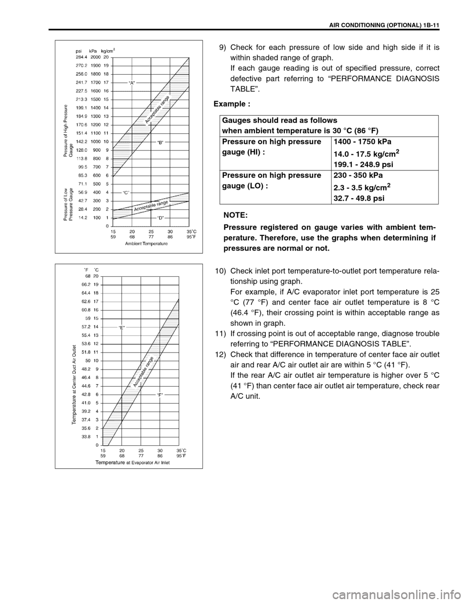
9) Check for each pressure of low side and high side if it is
within shaded range of graph.
If each gauge reading is out of specified pressure, correct
defective part referring to “PERFORMANCE DIAGNOSIS
TABLE”.
Example :
10) Check inlet port temperature-to-outlet port temperature rela-
tionship using graph.
For example, if A/C evaporator inlet port temperature is 25
°C (77 °F) and center face air outlet temperature is 8 °C
(46.4 °F), their crossing point is within acceptable range as
shown in graph.
11) If crossing point is out of acceptable range, diagnose trouble
referring to “PERFORMANCE DIAGNOSIS TABLE”.
12) Check that difference in temperature of center face air outlet
air and rear A/C air outlet air are within 5 °C (41 °F).
If the rear A/C air outlet air temperature is higher over 5 °C
(41 °F) than center face air outlet air temperature, check rear
A/C unit. Gauges should read as follows
when ambient temperature is 30 °C (86 °F)
Pressure on high pressure
gauge (HI) :1400 - 1750 kPa
14.0 - 17.5 kg/cm
2
199.1 - 248.9 psi
Pressure on high pressure
gauge (LO) :230 - 350 kPa
2.3 - 3.5 kg/cm
2
32.7 - 49.8 psi
NOTE:
Pressure registered on gauge varies with ambient tem-
perature. Therefore, use the graphs when determining if
pressures are normal or not.
Page 37 of 656
1B-12 AIR CONDITIONING (OPTIONAL)
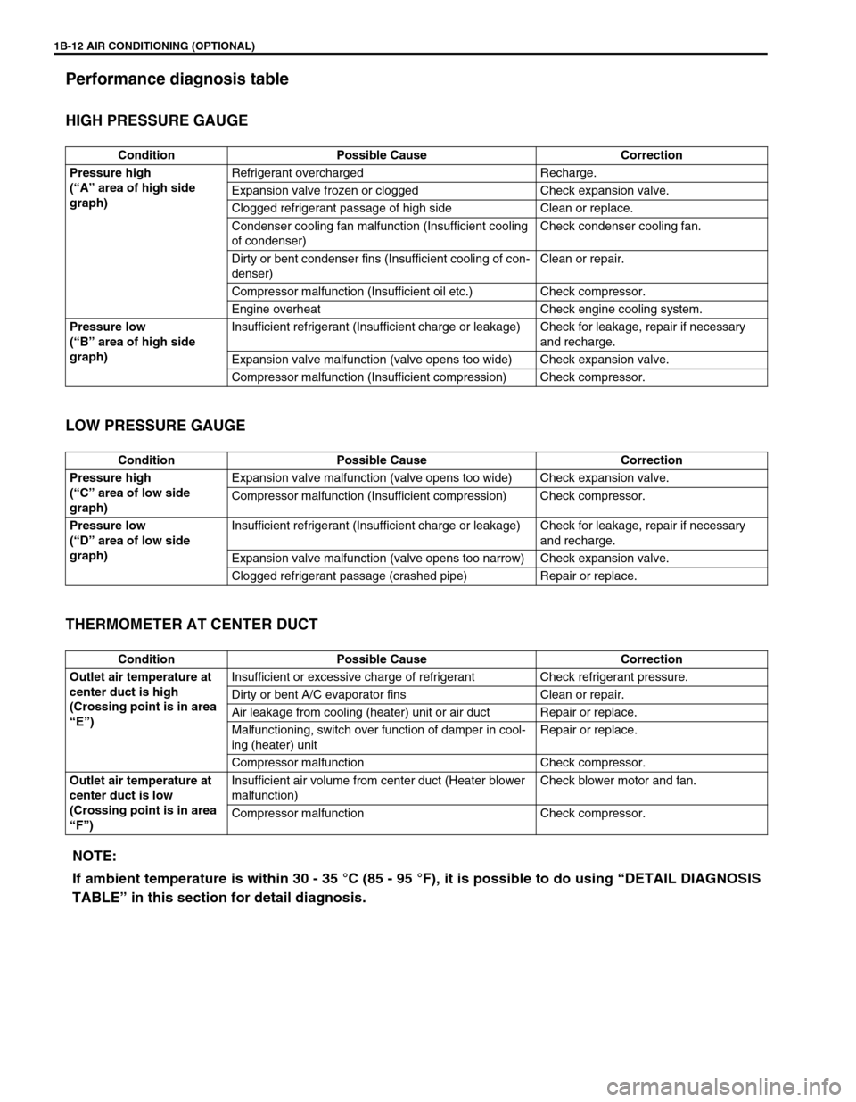
Performance diagnosis table
HIGH PRESSURE GAUGE
LOW PRESSURE GAUGE
THERMOMETER AT CENTER DUCT
Condition Possible Cause Correction
Pressure high
(“A” area of high side
graph)Refrigerant overcharged Recharge.
Expansion valve frozen or clogged Check expansion valve.
Clogged refrigerant passage of high side Clean or replace.
Condenser cooling fan malfunction (Insufficient cooling
of condenser)Check condenser cooling fan.
Dirty or bent condenser fins (Insufficient cooling of con-
denser)Clean or repair.
Compressor malfunction (Insufficient oil etc.) Check compressor.
Engine overheat Check engine cooling system.
Pressure low
(“B” area of high side
graph)Insufficient refrigerant (Insufficient charge or leakage) Check for leakage, repair if necessary
and recharge.
Expansion valve malfunction (valve opens too wide) Check expansion valve.
Compressor malfunction (Insufficient compression) Check compressor.
Condition Possible Cause Correction
Pressure high
(“C” area of low side
graph)Expansion valve malfunction (valve opens too wide) Check expansion valve.
Compressor malfunction (Insufficient compression) Check compressor.
Pressure low
(“D” area of low side
graph)Insufficient refrigerant (Insufficient charge or leakage) Check for leakage, repair if necessary
and recharge.
Expansion valve malfunction (valve opens too narrow) Check expansion valve.
Clogged refrigerant passage (crashed pipe) Repair or replace.
Condition Possible Cause Correction
Outlet air temperature at
center duct is high
(Crossing point is in area
“E”)Insufficient or excessive charge of refrigerant Check refrigerant pressure.
Dirty or bent A/C evaporator fins Clean or repair.
Air leakage from cooling (heater) unit or air duct Repair or replace.
Malfunctioning, switch over function of damper in cool-
ing (heater) unitRepair or replace.
Compressor malfunction Check compressor.
Outlet air temperature at
center duct is low
(Crossing point is in area
“F”)Insufficient air volume from center duct (Heater blower
malfunction)Check blower motor and fan.
Compressor malfunction Check compressor.
NOTE:
If ambient temperature is within 30 - 35 °C (85 - 95 °F), it is possible to do using “DETAIL DIAGNOSIS
TABLE” in this section for detail diagnosis.
Page 38 of 656
AIR CONDITIONING (OPTIONAL) 1B-13
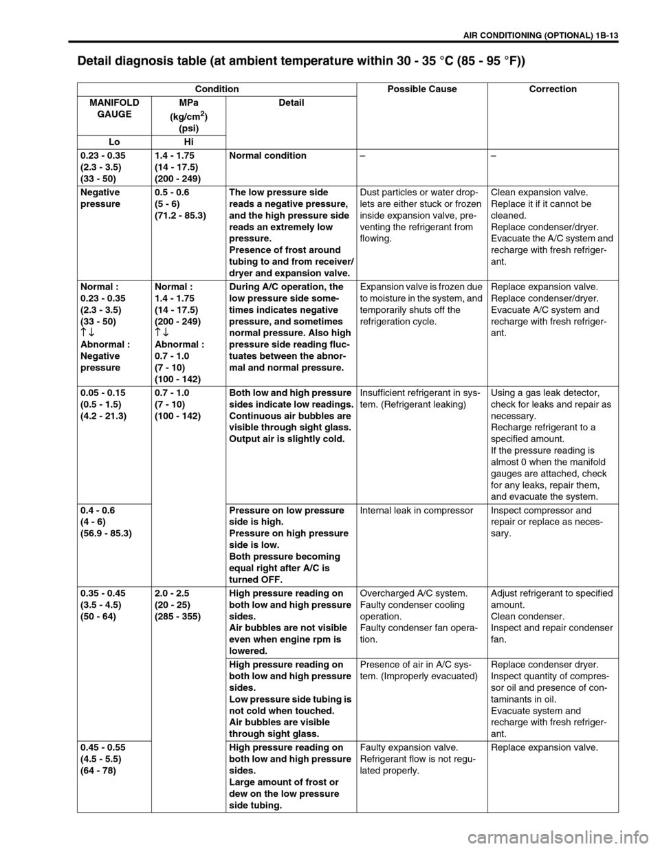
Detail diagnosis table (at ambient temperature within 30 - 35 °C (85 - 95 °F))
Condition Possible Cause Correction
MANIFOLD
GAUGEMPa
(kg/cm
2)
(psi)Detail
Lo Hi
0.23 - 0.35
(2.3 - 3.5)
(33 - 50)1.4 - 1.75
(14 - 17.5)
(200 - 249)Normal condition––
Negative
pressure0.5 - 0.6
(5 - 6)
(71.2 - 85.3)The low pressure side
reads a negative pressure,
and the high pressure side
reads an extremely low
pressure.
Presence of frost around
tubing to and from receiver/
dryer and expansion valve.Dust particles or water drop-
lets are either stuck or frozen
inside expansion valve, pre-
venting the refrigerant from
flowing.Clean expansion valve.
Replace it if it cannot be
cleaned.
Replace condenser/dryer.
Evacuate the A/C system and
recharge with fresh refriger-
ant.
Normal :
0.23 - 0.35
(2.3 - 3.5)
(33 - 50)
↑ ↓
↑ ↓↑ ↓ ↑ ↓
Abnormal :
Negative
pressureNormal :
1.4 - 1.75
(14 - 17.5)
(200 - 249)
↑ ↓
↑ ↓↑ ↓ ↑ ↓
Abnormal :
0.7 - 1.0
(7 - 10)
(100 - 142)During A/C operation, the
low pressure side some-
times indicates negative
pressure, and sometimes
normal pressure. Also high
pressure side reading fluc-
tuates between the abnor-
mal and normal pressure.Expansion valve is frozen due
to moisture in the system, and
temporarily shuts off the
refrigeration cycle.Replace expansion valve.
Replace condenser/dryer.
Evacuate A/C system and
recharge with fresh refriger-
ant.
0.05 - 0.15
(0.5 - 1.5)
(4.2 - 21.3)0.7 - 1.0
(7 - 10)
(100 - 142)Both low and high pressure
sides indicate low readings.
Continuous air bubbles are
visible through sight glass.
Output air is slightly cold.Insufficient refrigerant in sys-
tem. (Refrigerant leaking)Using a gas leak detector,
check for leaks and repair as
necessary.
Recharge refrigerant to a
specified amount.
If the pressure reading is
almost 0 when the manifold
gauges are attached, check
for any leaks, repair them,
and evacuate the system.
0.4 - 0.6
(4 - 6)
(56.9 - 85.3)Pressure on low pressure
side is high.
Pressure on high pressure
side is low.
Both pressure becoming
equal right after A/C is
turned OFF.Internal leak in compressor Inspect compressor and
repair or replace as neces-
sary.
0.35 - 0.45
(3.5 - 4.5)
(50 - 64)2.0 - 2.5
(20 - 25)
(285 - 355)High pressure reading on
both low and high pressure
sides.
Air bubbles are not visible
even when engine rpm is
lowered.Overcharged A/C system.
Faulty condenser cooling
operation.
Faulty condenser fan opera-
tion.Adjust refrigerant to specified
amount.
Clean condenser.
Inspect and repair condenser
fan.
High pressure reading on
both low and high pressure
sides.
Low pressure side tubing is
not cold when touched.
Air bubbles are visible
through sight glass.Presence of air in A/C sys-
tem. (Improperly evacuated)Replace condenser dryer.
Inspect quantity of compres-
sor oil and presence of con-
taminants in oil.
Evacuate system and
recharge with fresh refriger-
ant.
0.45 - 0.55
(4.5 - 5.5)
(64 - 78)High pressure reading on
both low and high pressure
sides.
Large amount of frost or
dew on the low pressure
side tubing.Faulty expansion valve.
Refrigerant flow is not regu-
lated properly.Replace expansion valve.
Page 39 of 656
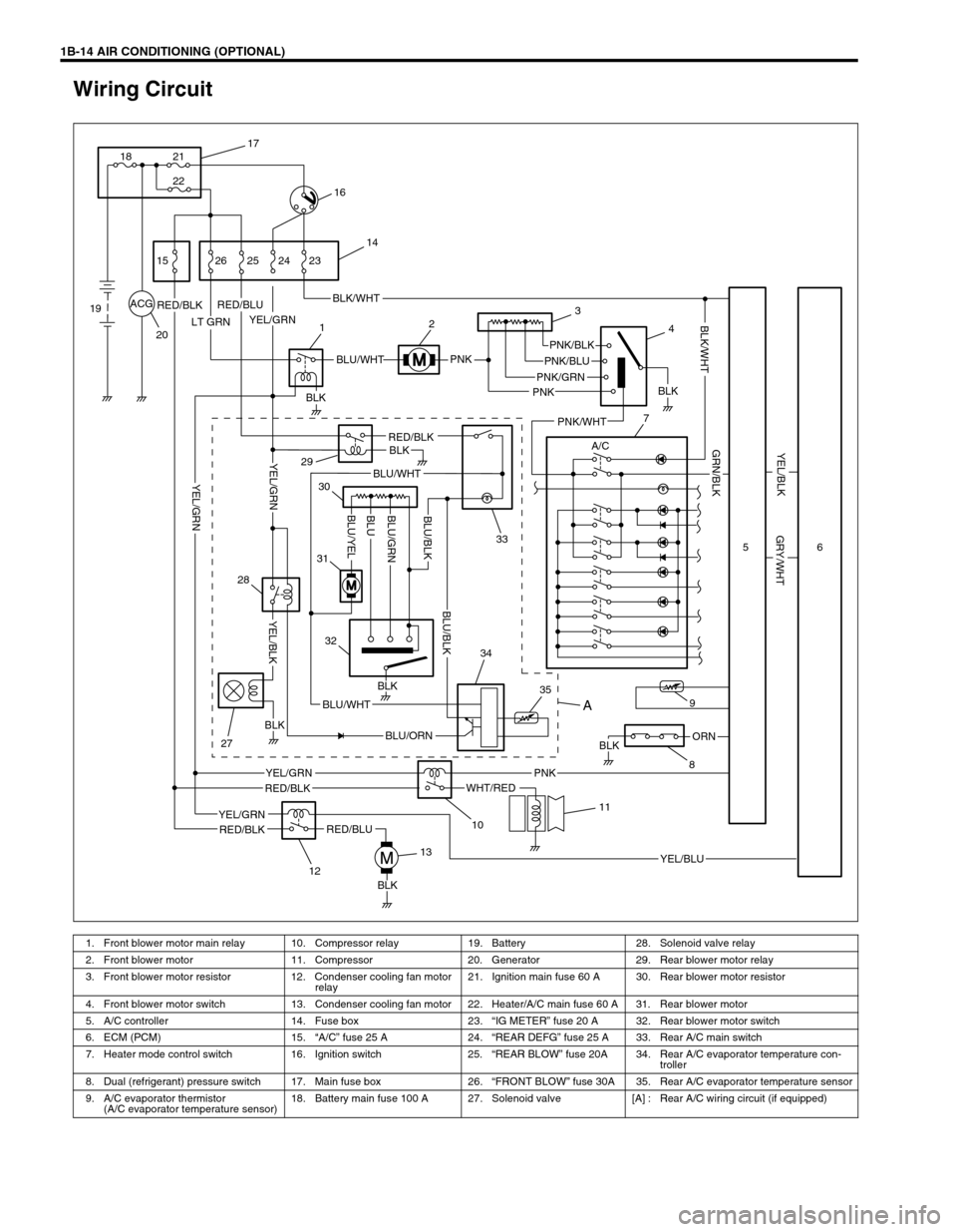
1B-14 AIR CONDITIONING (OPTIONAL)
Wiring Circuit
ACG
LT GRN
PNK
PNK
BLKORN
BLK
YEL/GRNRED/BLKBLK/WHT
BLU/WHTPNK/BLK
PNK/GRN
RED/BLK
WHT/RED
YEL/GRN
YEL/BLU
A/C
RED/BLU
RED/BLU
RED/BLKBLK
BLU/ORN
BLU/WHT
BLU/WHT
PNK
PNK/BLU
BLK
PNK/WHT
YEL/BLK
GRY/WHT
GRN/BLK
BLK/WHT
RED/BLK
YEL/GRN
BLK
BLK
BLK
YEL/BLK
YEL/GRN
YEL/GRNBLU/GRN
BLU/YELBLUBLU/BLK
BLU/BLK
17
21
22 18
16
15
19
2026 25 24 23
14
12
29
3
4
7
33 30
31
32
28
27
1213
10
11
35 349
856
A
1. Front blower motor main relay 10. Compressor relay 19. Battery 28. Solenoid valve relay
2. Front blower motor 11. Compressor 20. Generator 29. Rear blower motor relay
3. Front blower motor resistor 12. Condenser cooling fan motor
relay21. Ignition main fuse 60 A 30. Rear blower motor resistor
4. Front blower motor switch 13. Condenser cooling fan motor 22. Heater/A/C main fuse 60 A 31. Rear blower motor
5. A/C controller 14. Fuse box 23.“IG METER” fuse 20 A 32. Rear blower motor switch
6. ECM (PCM) 15.“A/C” fuse 25 A 24.“REAR DEFG” fuse 25 A 33. Rear A/C main switch
7. Heater mode control switch 16. Ignition switch 25.“REAR BLOW” fuse 20A 34. Rear A/C evaporator temperature con-
troller
8. Dual (refrigerant) pressure switch 17. Main fuse box 26.“FRONT BLOW” fuse 30A 35. Rear A/C evaporator temperature sensor
9. A/C evaporator thermistor
(A/C evaporator temperature sensor)18. Battery main fuse 100 A 27. Solenoid valve [A] : Rear A/C wiring circuit (if equipped)