Timing chain install SUZUKI GRAND VITARA 2001 2.G Owners Manual
[x] Cancel search | Manufacturer: SUZUKI, Model Year: 2001, Model line: GRAND VITARA, Model: SUZUKI GRAND VITARA 2001 2.GPages: 656, PDF Size: 14.31 MB
Page 242 of 656

ENGINE GENERAL INFORMATION AND DIAGNOSIS (H27 ENGINE) 6-1-81
TROUBLESHOOTING
Step Action Yes No
1 Was “ENGINE DIAG. FLOW TABLE” per-
formed?Go to Step 2. Go to “ENGINE DIAG.
FLOW TABLE” in this
section.
2 Ignition system inspection :
1) Check spark plug and ignition spark of cylin-
der where misfire occurs, referring to “IGNI-
TION SYSTEM” section.
Is it in good condition?Go to Step 3. Faulty ignition coil, wire
harness, or other system
parts.
3 Fuel injector circuit inspection :
1) Using sound scope, check each injector
operating sound at engine cranking or
idling.
Do all injectors make operating sound?Go to Step 4. Check coupler connec-
tion and wire harness of
injector not making oper-
ating sound and injector
itself.
If OK, substitute a known-
good ECM (PCM) and
recheck.
4 Fuel pressure inspection :
1) Check fuel pressure referring to “TABLE B-
3” in this section.
Is check result satisfactory?Go to Step 5. Repair or replace.
5 Fuel injector inspection :
1) Check fuel injector(s) referring to Section
6E2.
Is check result satisfactory?Go to Step 6. Replace.
6 Ignition timing inspection :
1) Check ignition timing referring to Section
6F2.
Is check result satisfactory?Go to Step 7. Adjust or check system
related parts.
7 EGR system inspection :
1) Check EGR system referring to Section
6E2.
Is check result satisfactory?Go to Step 8. Repair or replace.
8 Fuel level sensor inspection :
1) Check fuel level sensor referring to Section
6E2.
Is check result satisfactory?Go to Step 9. Repair or replace.
9 Check engine mechanical parts or system
which can cause engine rough idle or poor per-
formance.
• Engine compression (See Section 6A2).
• Valve lash or lash adjuster (See Section
6A2).
• Valve timing (Timing belt or chain installa-
tion. See Section 6A2).
Are they in good condition?Check wire harness and
connection of ECM (PCM)
ground, ignition system
and fuel injector for inter-
mittent open and short.Repair or replace.
Page 306 of 656

ENGINE MECHANICAL (H27 ENGINE) 6A2-19
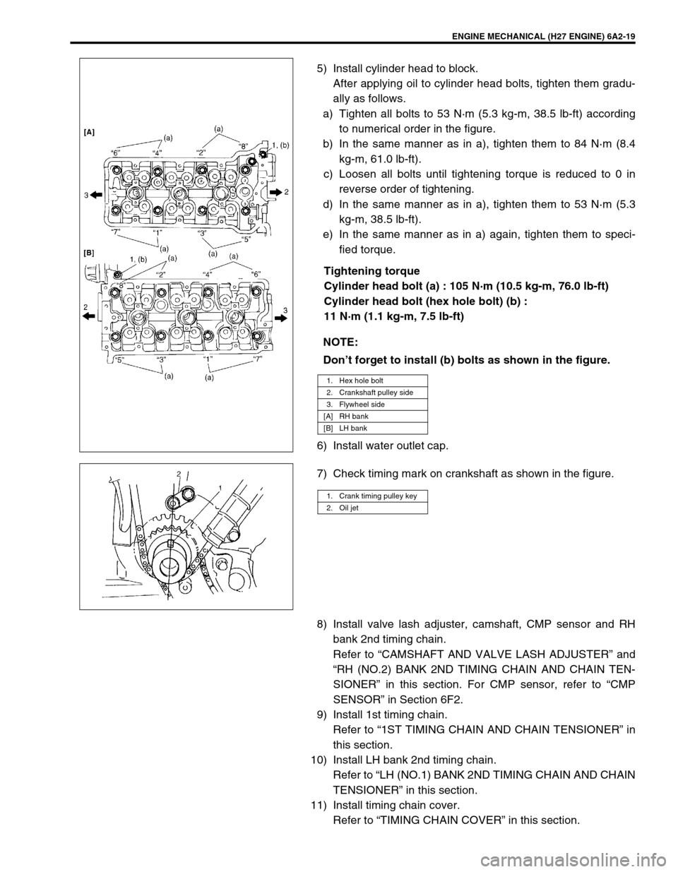
5) Install cylinder head to block.
After applying oil to cylinder head bolts, tighten them gradu-
ally as follows.
a) Tighten all bolts to 53 N·m (5.3 kg-m, 38.5 lb-ft) according
to numerical order in the figure.
b) In the same manner as in a), tighten them to 84 N·m (8.4
kg-m, 61.0 lb-ft).
c) Loosen all bolts until tightening torque is reduced to 0 in
reverse order of tightening.
d) In the same manner as in a), tighten them to 53 N·m (5.3
kg-m, 38.5 lb-ft).
e) In the same manner as in a) again, tighten them to speci-
fied torque.
Tightening torque
Cylinder head bolt (a) : 105 N·m (10.5 kg-m, 76.0 lb-ft)
Cylinder head bolt (hex hole bolt) (b) :
11 N·m (1.1 kg-m, 7.5 lb-ft)
6) Install water outlet cap.
7) Check timing mark on crankshaft as shown in the figure.
8) Install valve lash adjuster, camshaft, CMP sensor and RH
bank 2nd timing chain.
Refer to “CAMSHAFT AND VALVE LASH ADJUSTER” and
“RH (NO.2) BANK 2ND TIMING CHAIN AND CHAIN TEN-
SIONER” in this section. For CMP sensor, refer to “CMP
SENSOR” in Section 6F2.
9) Install 1st timing chain.
Refer to “1ST TIMING CHAIN AND CHAIN TENSIONER” in
this section.
10) Install LH bank 2nd timing chain.
Refer to “LH (NO.1) BANK 2ND TIMING CHAIN AND CHAIN
TENSIONER” in this section.
11) Install timing chain cover.
Refer to “TIMING CHAIN COVER” in this section. NOTE:
Don’t forget to install (b) bolts as shown in the figure.
1. Hex hole bolt
2. Crankshaft pulley side
3. Flywheel side
[A] RH bank
[B] LH bank
1. Crank timing pulley key
2. Oil jet