fuel pump SUZUKI GRAND VITARA 2001 2.G Owners Manual
[x] Cancel search | Manufacturer: SUZUKI, Model Year: 2001, Model line: GRAND VITARA, Model: SUZUKI GRAND VITARA 2001 2.GPages: 656, PDF Size: 14.31 MB
Page 163 of 656
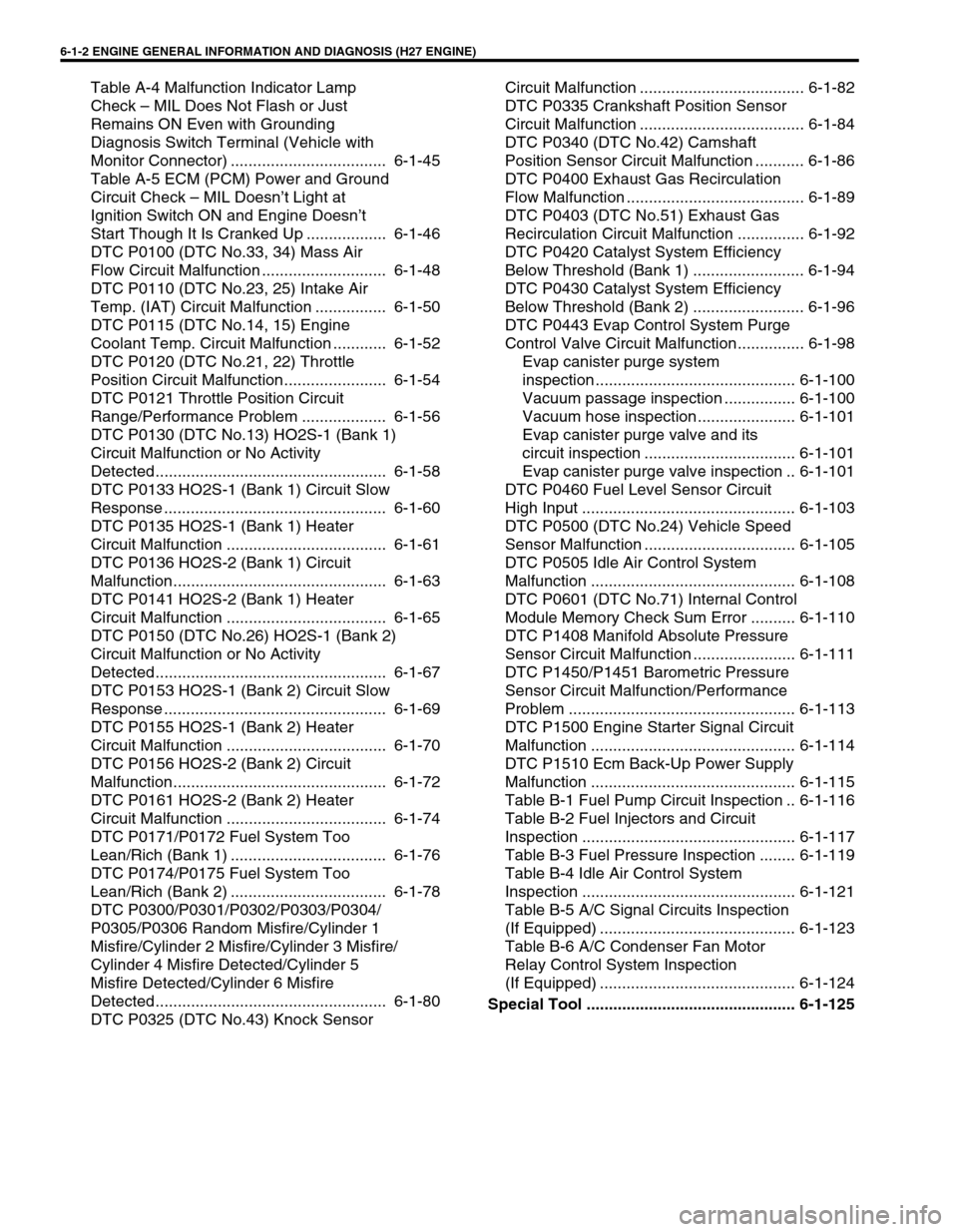
6-1-2 ENGINE GENERAL INFORMATION AND DIAGNOSIS (H27 ENGINE)
Table A-4 Malfunction Indicator Lamp
Check – MIL Does Not Flash or Just
Remains ON Even with Grounding
Diagnosis Switch Terminal (Vehicle with
Monitor Connector) ................................... 6-1-45
Table A-5 ECM (PCM) Power and Ground
Circuit Check – MIL Doesn’t Light at
Ignition Switch ON and Engine Doesn’t
Start Though It Is Cranked Up .................. 6-1-46
DTC P0100 (DTC No.33, 34) Mass Air
Flow Circuit Malfunction ............................ 6-1-48
DTC P0110 (DTC No.23, 25) Intake Air
Temp. (IAT) Circuit Malfunction ................ 6-1-50
DTC P0115 (DTC No.14, 15) Engine
Coolant Temp. Circuit Malfunction ............ 6-1-52
DTC P0120 (DTC No.21, 22) Throttle
Position Circuit Malfunction....................... 6-1-54
DTC P0121 Throttle Position Circuit
Range/Performance Problem ................... 6-1-56
DTC P0130 (DTC No.13) HO2S-1 (Bank 1)
Circuit Malfunction or No Activity
Detected.................................................... 6-1-58
DTC P0133 HO2S-1 (Bank 1) Circuit Slow
Response .................................................. 6-1-60
DTC P0135 HO2S-1 (Bank 1) Heater
Circuit Malfunction .................................... 6-1-61
DTC P0136 HO2S-2 (Bank 1) Circuit
Malfunction................................................ 6-1-63
DTC P0141 HO2S-2 (Bank 1) Heater
Circuit Malfunction .................................... 6-1-65
DTC P0150 (DTC No.26) HO2S-1 (Bank 2)
Circuit Malfunction or No Activity
Detected.................................................... 6-1-67
DTC P0153 HO2S-1 (Bank 2) Circuit Slow
Response .................................................. 6-1-69
DTC P0155 HO2S-1 (Bank 2) Heater
Circuit Malfunction .................................... 6-1-70
DTC P0156 HO2S-2 (Bank 2) Circuit
Malfunction................................................ 6-1-72
DTC P0161 HO2S-2 (Bank 2) Heater
Circuit Malfunction .................................... 6-1-74
DTC P0171/P0172 Fuel System Too
Lean/Rich (Bank 1) ................................... 6-1-76
DTC P0174/P0175 Fuel System Too
Lean/Rich (Bank 2) ................................... 6-1-78
DTC P0300/P0301/P0302/P0303/P0304/
P0305/P0306 Random Misfire/Cylinder 1
Misfire/Cylinder 2 Misfire/Cylinder 3 Misfire/
Cylinder 4 Misfire Detected/Cylinder 5
Misfire Detected/Cylinder 6 Misfire
Detected.................................................... 6-1-80
DTC P0325 (DTC No.43) Knock Sensor Circuit Malfunction ..................................... 6-1-82
DTC P0335 Crankshaft Position Sensor
Circuit Malfunction ..................................... 6-1-84
DTC P0340 (DTC No.42) Camshaft
Position Sensor Circuit Malfunction ........... 6-1-86
DTC P0400 Exhaust Gas Recirculation
Flow Malfunction ........................................ 6-1-89
DTC P0403 (DTC No.51) Exhaust Gas
Recirculation Circuit Malfunction ............... 6-1-92
DTC P0420 Catalyst System Efficiency
Below Threshold (Bank 1) ......................... 6-1-94
DTC P0430 Catalyst System Efficiency
Below Threshold (Bank 2) ......................... 6-1-96
DTC P0443 Evap Control System Purge
Control Valve Circuit Malfunction............... 6-1-98
Evap canister purge system
inspection ............................................. 6-1-100
Vacuum passage inspection ................ 6-1-100
Vacuum hose inspection ...................... 6-1-101
Evap canister purge valve and its
circuit inspection .................................. 6-1-101
Evap canister purge valve inspection .. 6-1-101
DTC P0460 Fuel Level Sensor Circuit
High Input ................................................ 6-1-103
DTC P0500 (DTC No.24) Vehicle Speed
Sensor Malfunction .................................. 6-1-105
DTC P0505 Idle Air Control System
Malfunction .............................................. 6-1-108
DTC P0601 (DTC No.71) Internal Control
Module Memory Check Sum Error .......... 6-1-110
DTC P1408 Manifold Absolute Pressure
Sensor Circuit Malfunction ....................... 6-1-111
DTC P1450/P1451 Barometric Pressure
Sensor Circuit Malfunction/Performance
Problem ................................................... 6-1-113
DTC P1500 Engine Starter Signal Circuit
Malfunction .............................................. 6-1-114
DTC P1510 Ecm Back-Up Power Supply
Malfunction .............................................. 6-1-115
Table B-1 Fuel Pump Circuit Inspection .. 6-1-116
Table B-2 Fuel Injectors and Circuit
Inspection ................................................ 6-1-117
Table B-3 Fuel Pressure Inspection ........ 6-1-119
Table B-4 Idle Air Control System
Inspection ................................................ 6-1-121
Table B-5 A/C Signal Circuits Inspection
(If Equipped) ............................................ 6-1-123
Table B-6 A/C Condenser Fan Motor
Relay Control System Inspection
(If Equipped) ............................................ 6-1-124
Special Tool ............................................... 6-1-125
Page 165 of 656
6-1-4 ENGINE GENERAL INFORMATION AND DIAGNOSIS (H27 ENGINE)
When disconnecting couplers, don’t pull wire harness but
make sure to hold coupler itself. With lock type coupler, be
sure to unlock before disconnection. Attempt to disconnect
coupler without unlocking may result in damage to coupler.
When connecting lock type coupler, insert it till clicking
sound is heard and connect it securely.
Precaution on Fuel System Service
Work must be done with no smoking, in a well-ventilated area and away from any open flames.
As fuel feed line (between fuel pump and fuel pressure regulator) is still under high fuel pressure even after
engine was stopped, loosening or disconnecting fuel feed line directly may cause dangerous spout of fuel to
occur where loosened or disconnected. Before loosening or disconnecting fuel feed line, make sure to
release fuel pressure according to “FUEL PRESSURE RELIEF PROCEDURE” in this section.
A small amount of fuel may be released after the fuel line is disconnected.
In order to reduce the chance of personal injury, cover the fitting to be disconnected with a shop cloth. Put
that cloth in an approved container when disconnection is completed.
Never run engine with fuel pump relay disconnected when engine and exhaust system are hot.
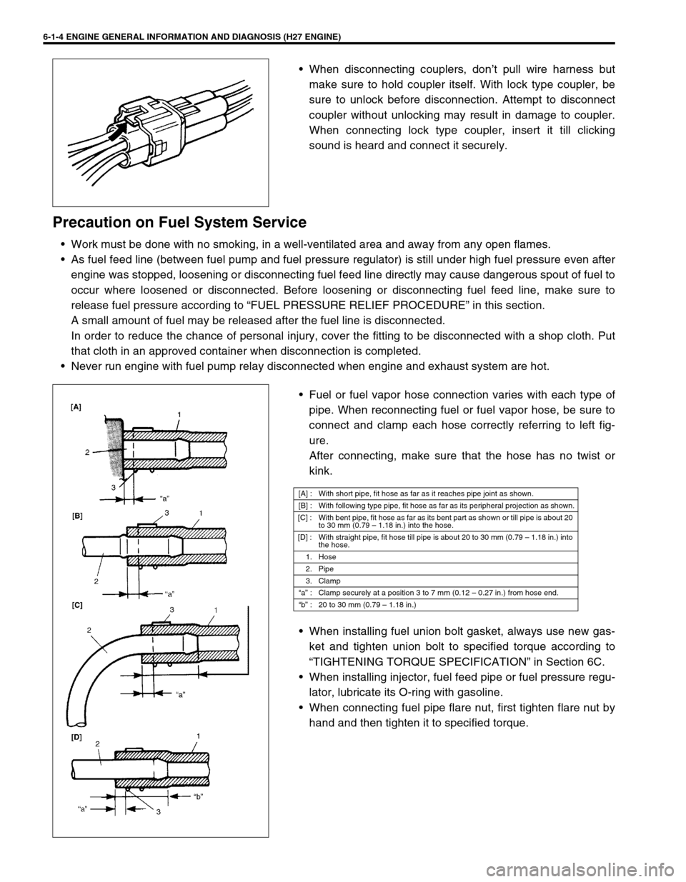
Fuel or fuel vapor hose connection varies with each type of
pipe. When reconnecting fuel or fuel vapor hose, be sure to
connect and clamp each hose correctly referring to left fig-
ure.
After connecting, make sure that the hose has no twist or
kink.
When installing fuel union bolt gasket, always use new gas-
ket and tighten union bolt to specified torque according to
“TIGHTENING TORQUE SPECIFICATION” in Section 6C.
When installing injector, fuel feed pipe or fuel pressure regu-
lator, lubricate its O-ring with gasoline.
When connecting fuel pipe flare nut, first tighten flare nut by
hand and then tighten it to specified torque.
[A] : With short pipe, fit hose as far as it reaches pipe joint as shown.
[B] : With following type pipe, fit hose as far as its peripheral projection as shown.
[C] : With bent pipe, fit hose as far as its bent part as shown or till pipe is about 20
to 30 mm (0.79 – 1.18 in.) into the hose.
[D] : With straight pipe, fit hose till pipe is about 20 to 30 mm (0.79 – 1.18 in.) into
the hose.
1. Hose
2. Pipe
3. Clamp
“a” : Clamp securely at a position 3 to 7 mm (0.12 – 0.27 in.) from hose end.
“b” : 20 to 30 mm (0.79 – 1.18 in.)
Page 166 of 656
ENGINE GENERAL INFORMATION AND DIAGNOSIS (H27 ENGINE) 6-1-5
Fuel Pressure Relief Procedure
After making sure that engine is cold, relief fuel pressure as fol-
lows.
1) Place transmission gear shift lever in “Neutral” (shift selector
lever to “P” range for A/T vehicle), set parking brake, and
block drive wheels.
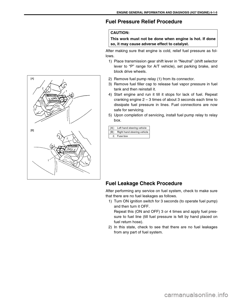
2) Remove fuel pump relay (1) from its connector.
3) Remove fuel filler cap to release fuel vapor pressure in fuel
tank and then reinstall it.
4) Start engine and run it till it stops for lack of fuel. Repeat
cranking engine 2 – 3 times of about 3 seconds each time to
dissipate fuel pressure in lines. Fuel connections are now
safe for servicing.
5) Upon completion of servicing, install fuel pump relay to relay
box.
Fuel Leakage Check Procedure
After performing any service on fuel system, check to make sure
that there are no fuel leakages as follows.
1) Turn ON ignition switch for 3 seconds (to operate fuel pump)
and then turn it OFF.
Repeat this (ON and OFF) 3 or 4 times and apply fuel pres-
sure to fuel line (till fuel pressure is felt by hand placed on
fuel return hose).
2) In this state, check to see that there are no fuel leakages
from any part of fuel system. CAUTION:
This work must not be done when engine is hot. If done
so, it may cause adverse effect to catalyst.
[A] : Left hand steering vehicle
[B] : Right hand steering vehicle
2. Fuse box
Page 174 of 656
ENGINE GENERAL INFORMATION AND DIAGNOSIS (H27 ENGINE) 6-1-13
STEP 2. DIAGNOSTIC TROUBLE CODE (DTC)/FREEZE FRAME DATA CHECK
First, check DTC, referring to “DIAGNOSTIC TROUBLE CODE CHECK” in this section. If DTC is indicated,
record DTC and freeze frame data.
After that clear DTC referring to “DIAGNOSTIC TROUBLE CODE CLEARANCE” in this section. DTC indicates
malfunction that occurred in the system but does not indicate whether it exists now or it occurred in the past and
the normal condition has been restored now. To check which case applies, check the symptom in question
according to Step 5 and recheck DTC according to Step 6, 7.
Attempt to diagnose a trouble based on DTC in this step only or failure to clear the DTC (including pending DTC)
in this step will lead to incorrect diagnosis, trouble diagnosis of a normal circuit or difficulty in troubleshooting.
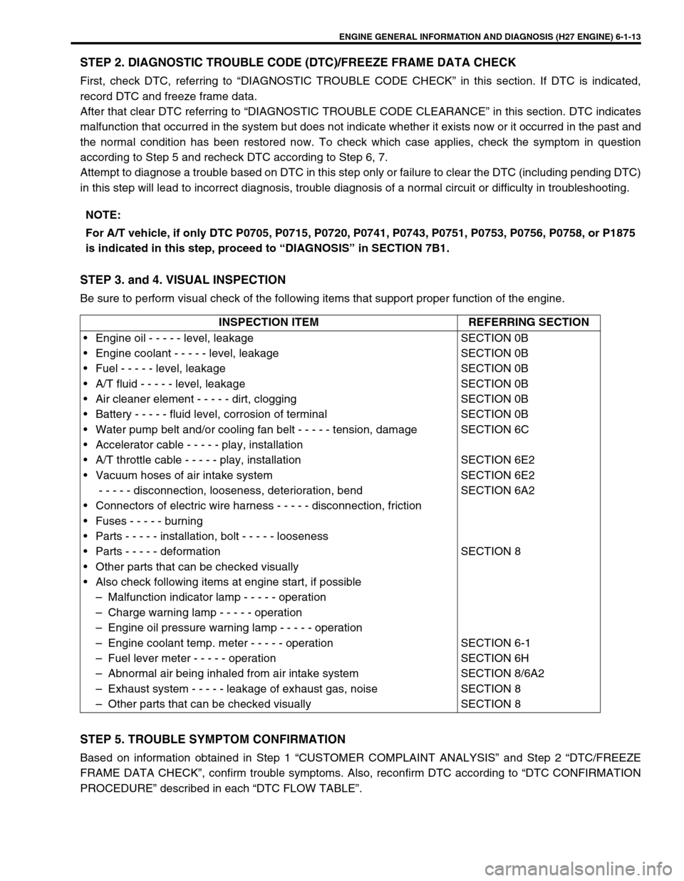
STEP 3. and 4. VISUAL INSPECTION
Be sure to perform visual check of the following items that support proper function of the engine.
STEP 5. TROUBLE SYMPTOM CONFIRMATION
Based on information obtained in Step 1 “CUSTOMER COMPLAINT ANALYSIS” and Step 2 “DTC/FREEZE
FRAME DATA CHECK”, confirm trouble symptoms. Also, reconfirm DTC according to “DTC CONFIRMATION
PROCEDURE” described in each “DTC FLOW TABLE”.NOTE:
For A/T vehicle, if only DTC P0705, P0715, P0720, P0741, P0743, P0751, P0753, P0756, P0758, or P1875
is indicated in this step, proceed to “DIAGNOSIS” in SECTION 7B1.
INSPECTION ITEM REFERRING SECTION
• Engine oil - - - - - level, leakage
• Engine coolant - - - - - level, leakage
• Fuel - - - - - level, leakage
• A/T fluid - - - - - level, leakage
• Air cleaner element - - - - - dirt, clogging
• Battery - - - - - fluid level, corrosion of terminal
• Water pump belt and/or cooling fan belt - - - - - tension, damage
• Accelerator cable - - - - - play, installation
• A/T throttle cable - - - - - play, installation
• Vacuum hoses of air intake system
- - - - - disconnection, looseness, deterioration, bend
• Connectors of electric wire harness - - - - - disconnection, friction
• Fuses - - - - - burning
• Parts - - - - - installation, bolt - - - - - looseness
• Parts - - - - - deformation
• Other parts that can be checked visually
• Also check following items at engine start, if possible
– Malfunction indicator lamp - - - - - operation
– Charge warning lamp - - - - - operation
– Engine oil pressure warning lamp - - - - - operation
– Engine coolant temp. meter - - - - - operation
– Fuel lever meter - - - - - operation
– Abnormal air being inhaled from air intake system
– Exhaust system - - - - - leakage of exhaust gas, noise
– Other parts that can be checked visuallySECTION 0B
SECTION 0B
SECTION 0B
SECTION 0B
SECTION 0B
SECTION 0B
SECTION 6C
SECTION 6E2
SECTION 6E2
SECTION 6A2
SECTION 8
SECTION 6-1
SECTION 6H
SECTION 8/6A2
SECTION 8
SECTION 8
Page 175 of 656
6-1-14 ENGINE GENERAL INFORMATION AND DIAGNOSIS (H27 ENGINE)
STEP 6. AND 7. RECHECKING AND RECORD OF DTC
Refer to “DTC Check” in this section for checking procedure.
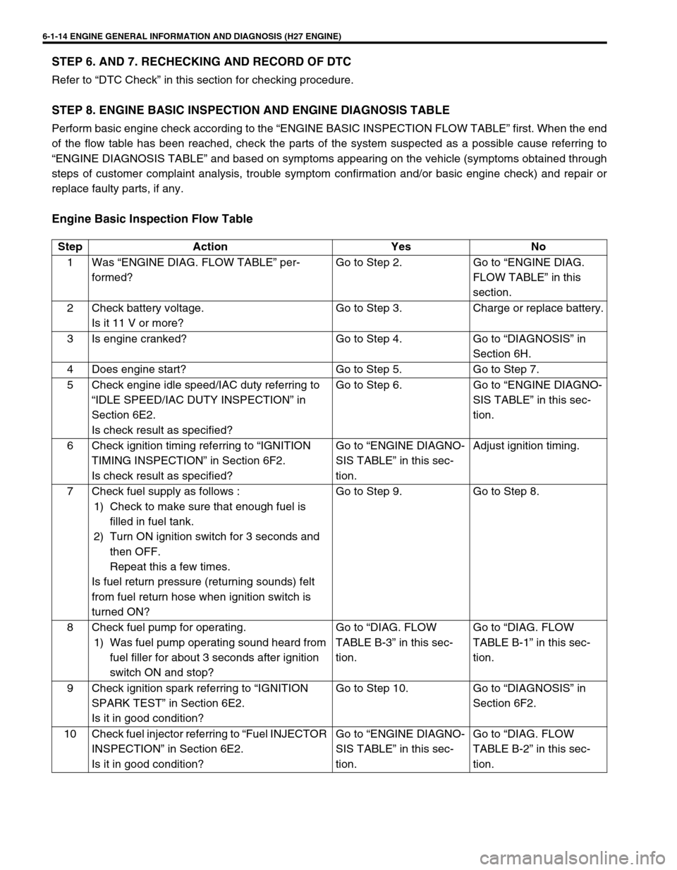
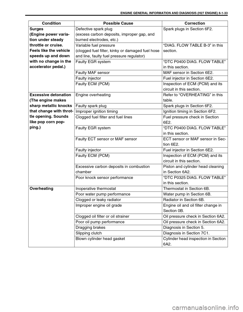
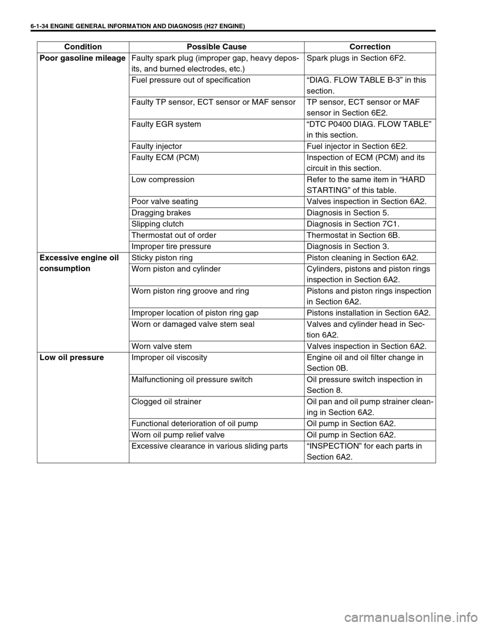
STEP 8. ENGINE BASIC INSPECTION AND ENGINE DIAGNOSIS TABLE
Perform basic engine check according to the “ENGINE BASIC INSPECTION FLOW TABLE” first. When the end
of the flow table has been reached, check the parts of the system suspected as a possible cause referring to
“ENGINE DIAGNOSIS TABLE” and based on symptoms appearing on the vehicle (symptoms obtained through
steps of customer complaint analysis, trouble symptom confirmation and/or basic engine check) and repair or
replace faulty parts, if any.
Engine Basic Inspection Flow Table
Step Action Yes No
1 Was “ENGINE DIAG. FLOW TABLE” per-
formed?Go to Step 2. Go to “ENGINE DIAG.
FLOW TABLE” in this
section.
2 Check battery voltage.
Is it 11 V or more?Go to Step 3. Charge or replace battery.
3 Is engine cranked? Go to Step 4. Go to “DIAGNOSIS” in
Section 6H.
4 Does engine start? Go to Step 5. Go to Step 7.
5 Check engine idle speed/IAC duty referring to
“IDLE SPEED/IAC DUTY INSPECTION” in
Section 6E2.
Is check result as specified?Go to Step 6. Go to “ENGINE DIAGNO-
SIS TABLE” in this sec-
tion.
6 Check ignition timing referring to “IGNITION
TIMING INSPECTION” in Section 6F2.
Is check result as specified?Go to “ENGINE DIAGNO-
SIS TABLE” in this sec-
tion.Adjust ignition timing.
7 Check fuel supply as follows :
1) Check to make sure that enough fuel is
filled in fuel tank.
2) Turn ON ignition switch for 3 seconds and
then OFF.
Repeat this a few times.
Is fuel return pressure (returning sounds) felt
from fuel return hose when ignition switch is
turned ON?Go to Step 9. Go to Step 8.
8 Check fuel pump for operating.
1) Was fuel pump operating sound heard from
fuel filler for about 3 seconds after ignition
switch ON and stop?Go to “DIAG. FLOW
TABLE B-3” in this sec-
tion.Go to “DIAG. FLOW
TABLE B-1” in this sec-
tion.
9 Check ignition spark referring to “IGNITION
SPARK TEST” in Section 6E2.
Is it in good condition?Go to Step 10. Go to “DIAGNOSIS” in
Section 6F2.
10 Check fuel injector referring to “Fuel INJECTOR
INSPECTION” in Section 6E2.
Is it in good condition?Go to “ENGINE DIAGNO-
SIS TABLE” in this sec-
tion.Go to “DIAG. FLOW
TABLE B-2” in this sec-
tion.
Page 192 of 656
ENGINE GENERAL INFORMATION AND DIAGNOSIS (H27 ENGINE) 6-1-31
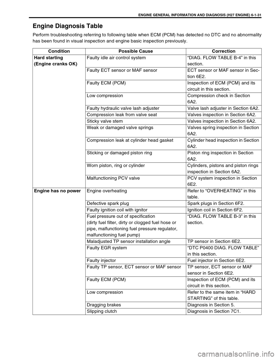
Engine Diagnosis Table
Perform troubleshooting referring to following table when ECM (PCM) has detected no DTC and no abnormality
has been found in visual inspection and engine basic inspection previously.
Condition Possible Cause Correction
Hard starting
(Engine cranks OK)Faulty idle air control system “DIAG. FLOW TABLE B-4” in this
section.
Faulty ECT sensor or MAF sensor ECT sensor or MAF sensor in Sec-
tion 6E2.
Faulty ECM (PCM) Inspection of ECM (PCM) and its
circuit in this section.
Low compression Compression check in Section
6A2.
Faulty hydraulic valve lash adjuster Valve lash adjuster in Section 6A2.
Compression leak from valve seat Valves inspection in Section 6A2.
Sticky valve stem Valves inspection in Section 6A2.
Weak or damaged valve springs Valves spring inspection in Section
6A2.
Compression leak at cylinder head gasket Cylinder head inspection in Section
6A2.
Sticking or damaged piston ring Piston ring inspection in Section
6A2.
Worn piston, ring or cylinder Cylinders, pistons and piston rings
inspection in Section 6A2.
Malfunctioning PCV valve PCV system inspection in Section
6E2.
Engine has no power
Engine overheating Refer to “OVERHEATING” in this
table.
Defective spark plug Spark plugs in Section 6F2.
Faulty ignition coil with ignitor Ignition coil in Section 6F2.
Fuel pressure out of specification
(dirty fuel filter, dirty or clogged fuel hose or
pipe, malfunctioning fuel pressure regulator,
malfunctioning fuel pump)“DIAG. FLOW TABLE B-3” in this
section.
Maladjusted TP sensor installation angle TP sensor in Section 6E2.
Faulty EGR system “DTC P0400 DIAG. FLOW TABLE”
in this section.
Faulty injector Fuel injector in Section 6E2.
Faulty TP sensor, ECT sensor or MAF sensor TP sensor, ECT sensor or MAF
sensor in Section 6E2.
Faulty ECM (PCM) Inspection of ECM (PCM) and its
circuit in this section.
Low compression Refer to the same item in “HARD
STARTING” of this table.
Dragging brakes Diagnosis in Section 5.
Slipping clutch Diagnosis in Section 7C1.
Page 194 of 656
ENGINE GENERAL INFORMATION AND DIAGNOSIS (H27 ENGINE) 6-1-33
Surges
(Engine power varia-
tion under steady
throttle or cruise.
Feels like the vehicle
speeds up and down
with no change in the
accelerator pedal.)Defective spark plug
(excess carbon deposits, improper gap, and
burned electrodes, etc.)Spark plugs in Section 6F2.
Variable fuel pressure
(clogged fuel filter, kinky or damaged fuel hose
and line, faulty fuel pressure regulator)“DIAG. FLOW TABLE B-3” in this
section.
Faulty EGR system “DTC P0400 DIAG. FLOW TABLE”
in this section.
Faulty MAF sensor MAF sensor in Section 6E2.
Faulty injector Fuel injector in Section 6E2.
Faulty ECM (PCM) Inspection of ECM (PCM) and its
circuit in this section.
Excessive detonation
(The engine makes
sharp metallic knocks
that change with throt-
tle opening. Sounds
like pop corn pop-
ping.)Engine overheating Refer to “OVERHEATING” in this
table.
Faulty spark plug Spark plugs in Section 6F2.
Improper ignition timing Ignition timing in Section 6F2.
Clogged fuel filter and fuel lines Fuel pressure check in Section
6E2.
Faulty EGR system “DTC P0400 DIAG. FLOW TABLE”
in this section.
Faulty ECT sensor or MAF sensor ECT sensor or MAF sensor in Sec-
tion 6E2.
Faulty injector Fuel injector in Section 6E2.
Faulty ECM (PCM) Inspection of ECM (PCM) and its
circuit in this section.
Excessive carbon deposits in combustion
chamberPiston and cylinder head cleaning
in Section 6A2.
Poor knock sensor performance “DTC P0325 DIAG. FLOW TABLE”
in this section.
Overheating
Inoperative thermostat Thermostat in Section 6B.
Poor water pump performance Water pump in Section 6B.
Clogged or leaky radiator Radiator in Section 6B.
Improper engine oil grade Engine oil and oil filter change in
Section 0B.
Clogged oil filter or oil strainer Oil pressure check in Section 6A2.
Poor oil pump performance Oil pressure check in Section 6A2.
Dragging brakes Diagnosis in Section 5.
Slipping clutch Diagnosis in Section 7C1.
Blown cylinder head gasket Cylinder head inspection in Section
6A2. Condition Possible Cause Correction
Page 195 of 656
6-1-34 ENGINE GENERAL INFORMATION AND DIAGNOSIS (H27 ENGINE)
Poor gasoline mileage
Faulty spark plug (improper gap, heavy depos-
its, and burned electrodes, etc.)Spark plugs in Section 6F2.
Fuel pressure out of specification “DIAG. FLOW TABLE B-3” in this
section.
Faulty TP sensor, ECT sensor or MAF sensor TP sensor, ECT sensor or MAF
sensor in Section 6E2.
Faulty EGR system “DTC P0400 DIAG. FLOW TABLE”
in this section.
Faulty injector Fuel injector in Section 6E2.
Faulty ECM (PCM) Inspection of ECM (PCM) and its
circuit in this section.
Low compression Refer to the same item in “HARD
STARTING” of this table.
Poor valve seating Valves inspection in Section 6A2.
Dragging brakes Diagnosis in Section 5.
Slipping clutch Diagnosis in Section 7C1.
Thermostat out of order Thermostat in Section 6B.
Improper tire pressure Diagnosis in Section 3.
Excessive engine oil
consumptionSticky piston ring Piston cleaning in Section 6A2.
Worn piston and cylinder Cylinders, pistons and piston rings
inspection in Section 6A2.
Worn piston ring groove and ring Pistons and piston rings inspection
in Section 6A2.
Improper location of piston ring gap Pistons installation in Section 6A2.
Worn or damaged valve stem seal Valves and cylinder head in Sec-
tion 6A2.
Worn valve stem Valves inspection in Section 6A2.
Low oil pressure
Improper oil viscosity Engine oil and oil filter change in
Section 0B.
Malfunctioning oil pressure switch Oil pressure switch inspection in
Section 8.
Clogged oil strainer Oil pan and oil pump strainer clean-
ing in Section 6A2.
Functional deterioration of oil pump Oil pump in Section 6A2.
Worn oil pump relief valve Oil pump in Section 6A2.
Excessive clearance in various sliding parts “INSPECTION” for each parts in
Section 6A2. Condition Possible Cause Correction
Page 199 of 656
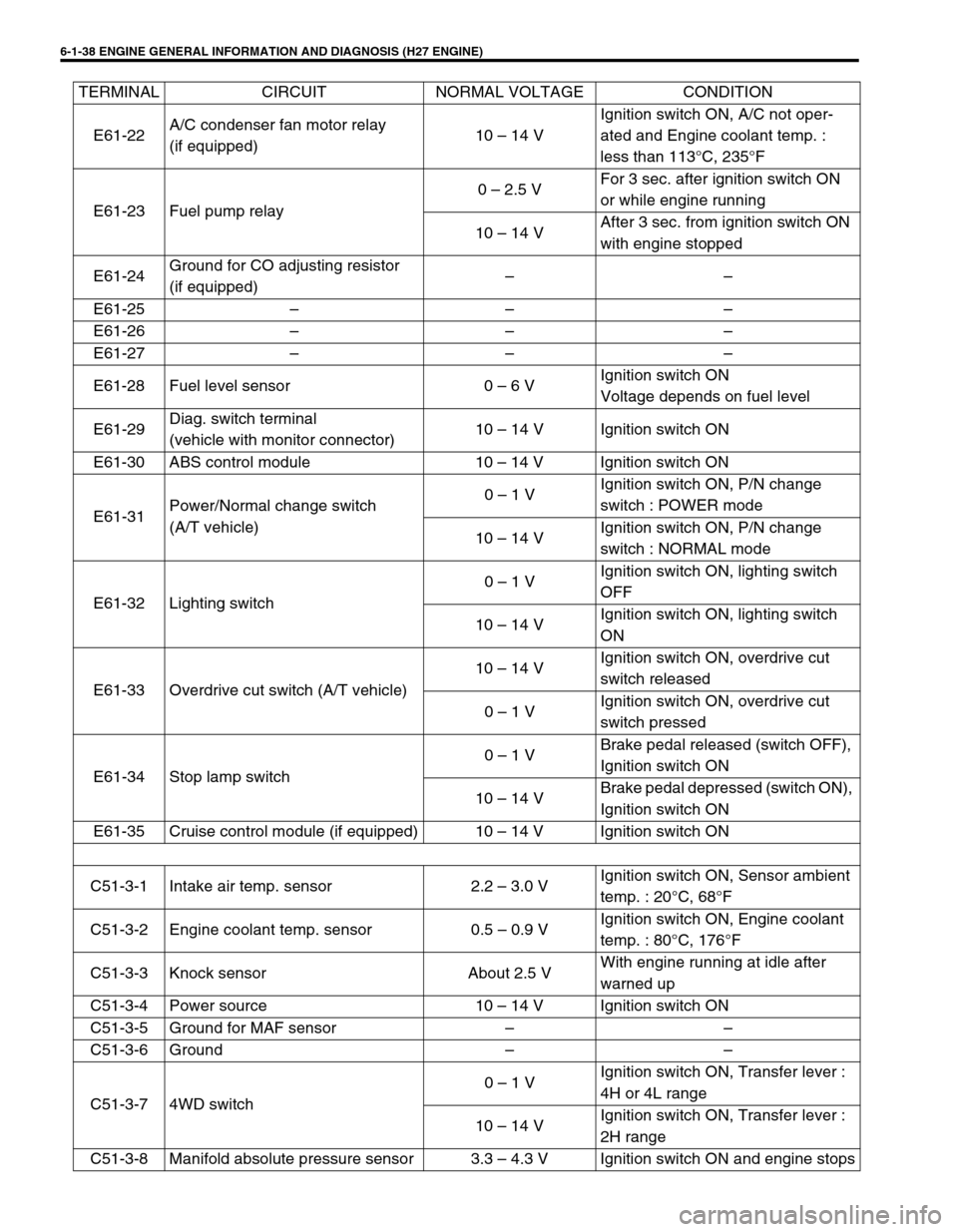
6-1-38 ENGINE GENERAL INFORMATION AND DIAGNOSIS (H27 ENGINE)
E61-22A/C condenser fan motor relay
(if equipped)10 – 14 VIgnition switch ON, A/C not oper-
ated and Engine coolant temp. :
less than 113°C, 235°F
E61-23 Fuel pump relay0 – 2.5 VFor 3 sec. after ignition switch ON
or while engine running
10 – 14 VAfter 3 sec. from ignition switch ON
with engine stopped
E61-24Ground for CO adjusting resistor
(if equipped)––
E61-25 – – –
E61-26 – – –
E61-27 – – –
E61-28 Fuel level sensor 0 – 6 VIgnition switch ON
Voltage depends on fuel level
E61-29Diag. switch terminal
(vehicle with monitor connector)10 – 14 V Ignition switch ON
E61-30 ABS control module 10 – 14 V Ignition switch ON
E61-31Power/Normal change switch
(A/T vehicle)0 – 1 VIgnition switch ON, P/N change
switch : POWER mode
10 – 14 VIgnition switch ON, P/N change
switch : NORMAL mode
E61-32 Lighting switch0 – 1 VIgnition switch ON, lighting switch
OFF
10 – 14 VIgnition switch ON, lighting switch
ON
E61-33 Overdrive cut switch (A/T vehicle)10 – 14 VIgnition switch ON, overdrive cut
switch released
0 – 1 VIgnition switch ON, overdrive cut
switch pressed
E61-34 Stop lamp switch0 – 1 VBrake pedal released (switch OFF),
Ignition switch ON
10 – 14 VBrake pedal depressed (switch ON),
Ignition switch ON
E61-35 Cruise control module (if equipped) 10 – 14 V Ignition switch ON
C51-3-1 Intake air temp. sensor 2.2 – 3.0 VIgnition switch ON, Sensor ambient
temp. : 20°C, 68°F
C51-3-2 Engine coolant temp. sensor 0.5 – 0.9 VIgnition switch ON, Engine coolant
temp. : 80°C, 176°F
C51-3-3 Knock sensor About 2.5 VWith engine running at idle after
warned up
C51-3-4 Power source 10 – 14 V Ignition switch ON
C51-3-5 Ground for MAF sensor – –
C51-3-6 Ground – –
C51-3-7 4WD switch0 – 1 VIgnition switch ON, Transfer lever :
4H or 4L range
10 – 14 VIgnition switch ON, Transfer lever :
2H range
C51-3-8 Manifold absolute pressure sensor 3.3 – 4.3 V Ignition switch ON and engine stops TERMINAL CIRCUIT NORMAL VOLTAGE CONDITION
Page 203 of 656
6-1-42 ENGINE GENERAL INFORMATION AND DIAGNOSIS (H27 ENGINE)
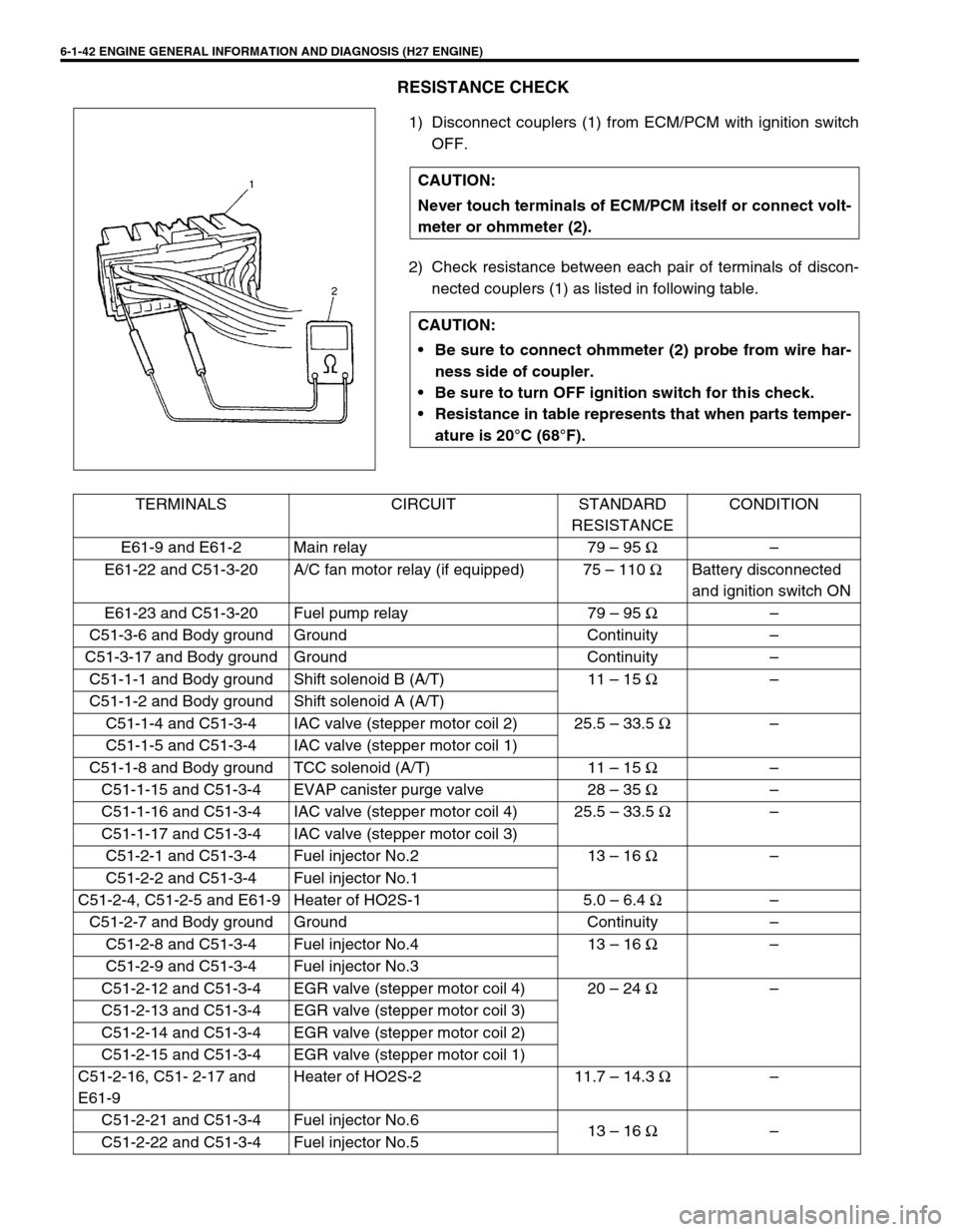
RESISTANCE CHECK
1) Disconnect couplers (1) from ECM/PCM with ignition switch
OFF.
2) Check resistance between each pair of terminals of discon-
nected couplers (1) as listed in following table. CAUTION:
Never touch terminals of ECM/PCM itself or connect volt-
meter or ohmmeter (2).
CAUTION:
Be sure to connect ohmmeter (2) probe from wire har-
ness side of coupler.
Be sure to turn OFF ignition switch for this check.
Resistance in table represents that when parts temper-
ature is 20°C (68°F).
TERMINALS CIRCUIT STANDARD
RESISTANCECONDITION
E61-9 and E61-2 Main relay 79 – 95 Ω–
E61-22 and C51-3-20 A/C fan motor relay (if equipped) 75 – 110 ΩBattery disconnected
and ignition switch ON
E61-23 and C51-3-20 Fuel pump relay 79 – 95 Ω–
C51-3-6 and Body ground Ground Continuity –
C51-3-17 and Body ground Ground Continuity –
C51-1-1 and Body ground Shift solenoid B (A/T) 11 – 15 Ω–
C51-1-2 and Body ground Shift solenoid A (A/T)
C51-1-4 and C51-3-4 IAC valve (stepper motor coil 2) 25.5 – 33.5 Ω–
C51-1-5 and C51-3-4 IAC valve (stepper motor coil 1)
C51-1-8 and Body ground TCC solenoid (A/T) 11 – 15 Ω–
C51-1-15 and C51-3-4 EVAP canister purge valve 28 – 35 Ω–
C51-1-16 and C51-3-4 IAC valve (stepper motor coil 4) 25.5 – 33.5 Ω–
C51-1-17 and C51-3-4 IAC valve (stepper motor coil 3)
C51-2-1 and C51-3-4 Fuel injector No.2 13 – 16 Ω–
C51-2-2 and C51-3-4 Fuel injector No.1
C51-2-4, C51-2-5 and E61-9 Heater of HO2S-1 5.0 – 6.4 Ω–
C51-2-7 and Body ground Ground Continuity –
C51-2-8 and C51-3-4 Fuel injector No.4 13 – 16 Ω–
C51-2-9 and C51-3-4 Fuel injector No.3
C51-2-12 and C51-3-4 EGR valve (stepper motor coil 4) 20 – 24 Ω–
C51-2-13 and C51-3-4 EGR valve (stepper motor coil 3)
C51-2-14 and C51-3-4 EGR valve (stepper motor coil 2)
C51-2-15 and C51-3-4 EGR valve (stepper motor coil 1)
C51-2-16, C51- 2-17 and
E61-9Heater of HO2S-2 11.7 – 14.3 Ω–
C51-2-21 and C51-3-4 Fuel injector No.6
13 – 16 Ω–
C51-2-22 and C51-3-4 Fuel injector No.5