high mount SUZUKI GRAND VITARA 2001 2.G Owners Manual
[x] Cancel search | Manufacturer: SUZUKI, Model Year: 2001, Model line: GRAND VITARA, Model: SUZUKI GRAND VITARA 2001 2.GPages: 656, PDF Size: 14.31 MB
Page 8 of 656
GENERAL INFORMATION 0A-3
Servicing and handling
WARNING:
Many of service procedures require disconnection of
“AIR BAG” fuse and all air bag (inflator) module(s) from
initiator circuit to avoid an accidental deployment.
Driver and Passenger Air Bag (Inflator) Modules
For handling and storage of a live air bag (inflator)
module, select a place where the ambient temperature
below 65°C (150°F), without high humidity and away
from electric noise.
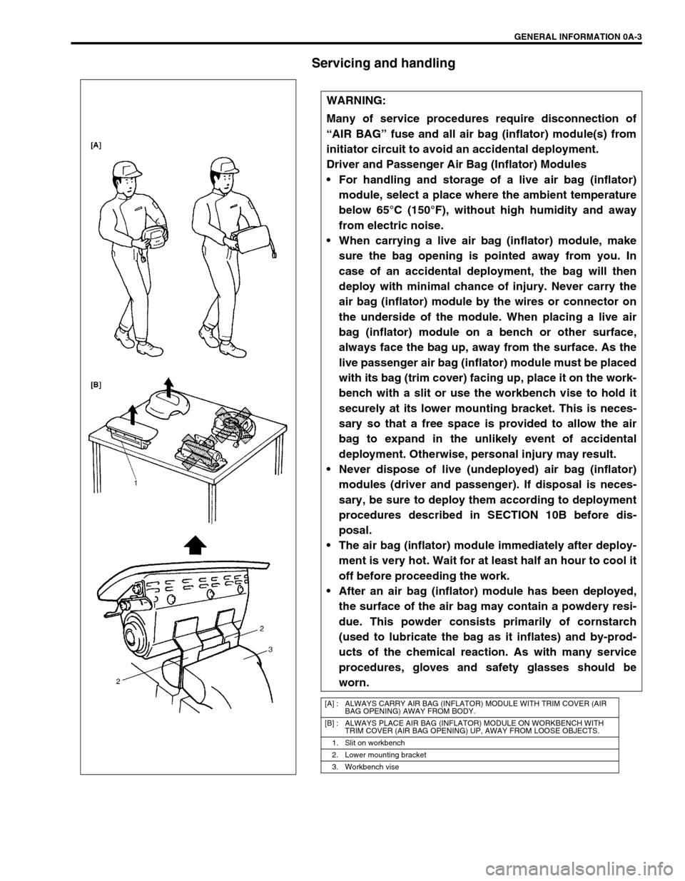
When carrying a live air bag (inflator) module, make
sure the bag opening is pointed away from you. In
case of an accidental deployment, the bag will then
deploy with minimal chance of injury. Never carry the
air bag (inflator) module by the wires or connector on
the underside of the module. When placing a live air
bag (inflator) module on a bench or other surface,
always face the bag up, away from the surface. As the
live passenger air bag (inflator) module must be placed
with its bag (trim cover) facing up, place it on the work-
bench with a slit or use the workbench vise to hold it
securely at its lower mounting bracket. This is neces-
sary so that a free space is provided to allow the air
bag to expand in the unlikely event of accidental
deployment. Otherwise, personal injury may result.
Never dispose of live (undeployed) air bag (inflator)
modules (driver and passenger). If disposal is neces-
sary, be sure to deploy them according to deployment
procedures described in SECTION 10B before dis-
posal.
The air bag (inflator) module immediately after deploy-
ment is very hot. Wait for at least half an hour to cool it
off before proceeding the work.
After an air bag (inflator) module has been deployed,
the surface of the air bag may contain a powdery resi-
due. This powder consists primarily of cornstarch
(used to lubricate the bag as it inflates) and by-prod-
ucts of the chemical reaction. As with many service
procedures, gloves and safety glasses should be
worn.
[A] : ALWAYS CARRY AIR BAG (INFLATOR) MODULE WITH TRIM COVER (AIR
BAG OPENING) AWAY FROM BODY.
[B] : ALWAYS PLACE AIR BAG (INFLATOR) MODULE ON WORKBENCH WITH
TRIM COVER (AIR BAG OPENING) UP, AWAY FROM LOOSE OBJECTS.
1. Slit on workbench
2. Lower mounting bracket
3. Workbench vise
Page 9 of 656
0A-4 GENERAL INFORMATION
WARNING:
SDM
During service procedures, be very careful when handling a Sensing and Diagnostic Module (SDM).
Never strike or jar the SDM.
Never power up the air bag system when the SDM is not rigidly attached to the vehicle. All SDM and
mounting bracket fasteners must be carefully torqued and the arrow must be pointing toward the
front of the vehicle to ensure proper operation of the air bag system.
The SDM could be activated when powered while not rigidly attached to the vehicle which could
cause deployment and result in personal injury.
WARNING:
Driver and Passenger Seat Belt Pretensioners
For handling and storage of a live seat belt preten-
sioner, select a place where the ambient temperature
below 65°C (150°F), without high humidity and away
from electric noise.
Never carry seat belt pretensioner by wire or connec-
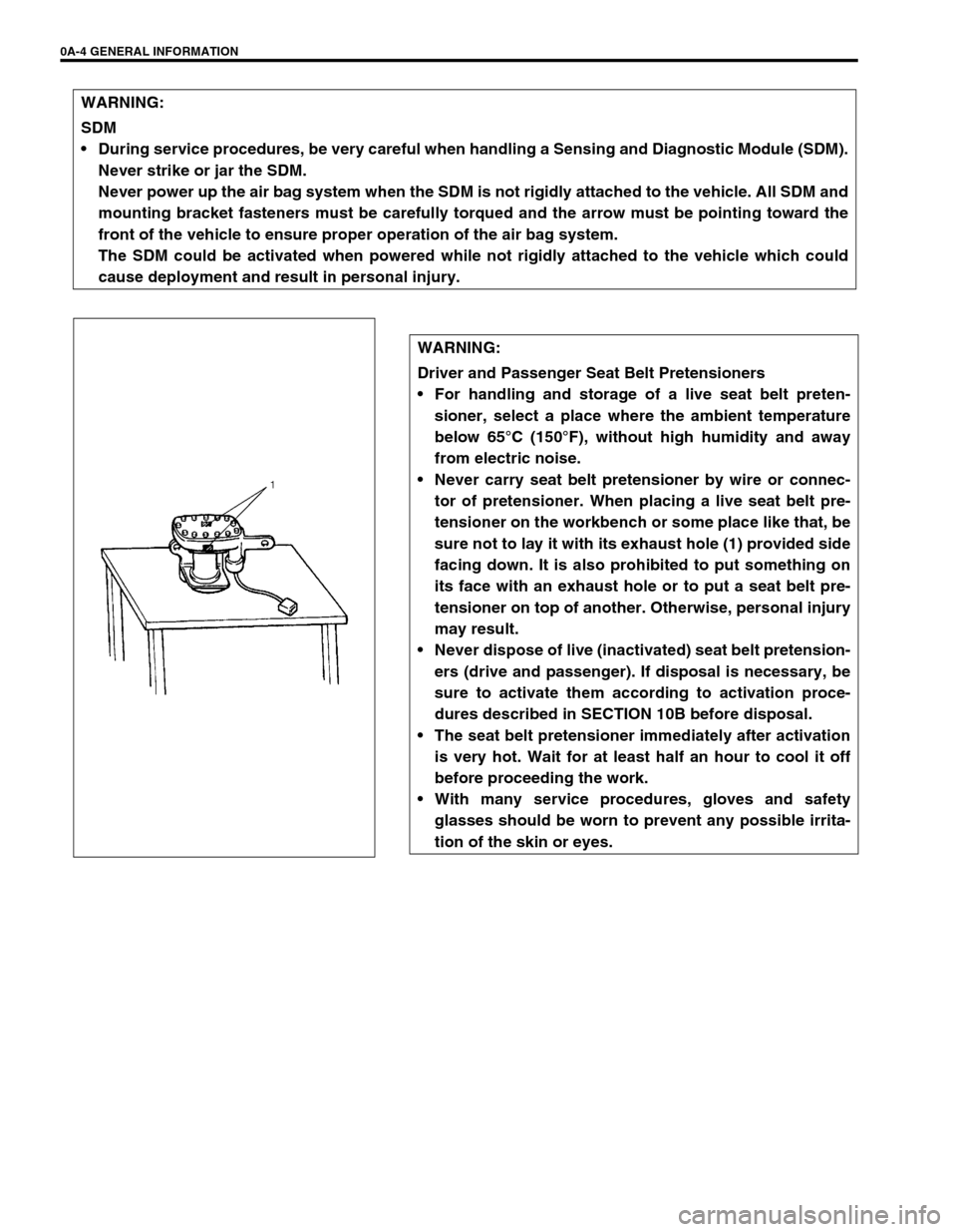
tor of pretensioner. When placing a live seat belt pre-
tensioner on the workbench or some place like that, be
sure not to lay it with its exhaust hole (1) provided side
facing down. It is also prohibited to put something on
its face with an exhaust hole or to put a seat belt pre-
tensioner on top of another. Otherwise, personal injury
may result.
Never dispose of live (inactivated) seat belt pretension-
ers (drive and passenger). If disposal is necessary, be
sure to activate them according to activation proce-
dures described in SECTION 10B before disposal.
The seat belt pretensioner immediately after activation
is very hot. Wait for at least half an hour to cool it off
before proceeding the work.
With many service procedures, gloves and safety
glasses should be worn to prevent any possible irrita-
tion of the skin or eyes.
Page 38 of 656
AIR CONDITIONING (OPTIONAL) 1B-13
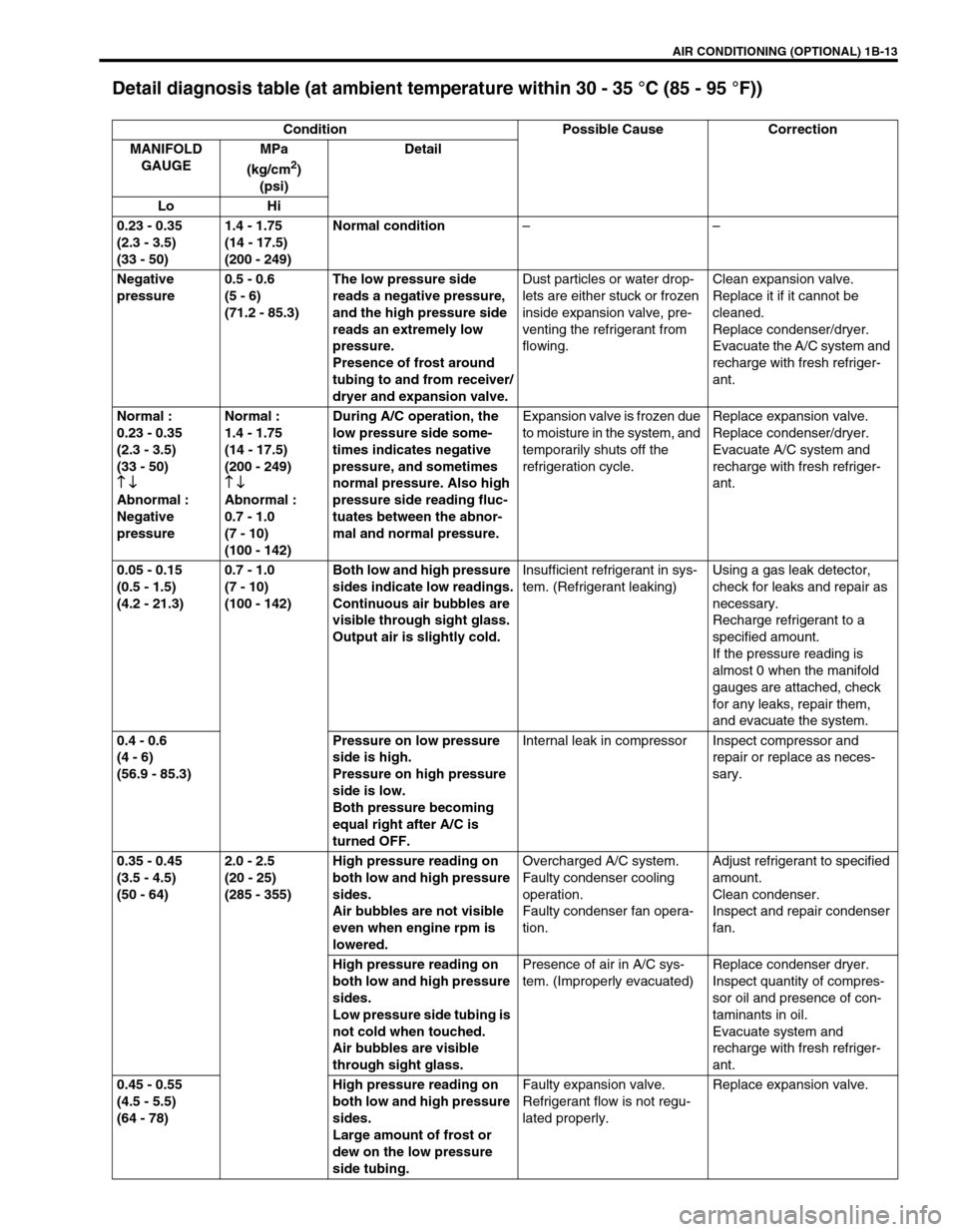
Detail diagnosis table (at ambient temperature within 30 - 35 °C (85 - 95 °F))
Condition Possible Cause Correction
MANIFOLD
GAUGEMPa
(kg/cm
2)
(psi)Detail
Lo Hi
0.23 - 0.35
(2.3 - 3.5)
(33 - 50)1.4 - 1.75
(14 - 17.5)
(200 - 249)Normal condition––
Negative
pressure0.5 - 0.6
(5 - 6)
(71.2 - 85.3)The low pressure side
reads a negative pressure,
and the high pressure side
reads an extremely low
pressure.
Presence of frost around
tubing to and from receiver/
dryer and expansion valve.Dust particles or water drop-
lets are either stuck or frozen
inside expansion valve, pre-
venting the refrigerant from
flowing.Clean expansion valve.
Replace it if it cannot be
cleaned.
Replace condenser/dryer.
Evacuate the A/C system and
recharge with fresh refriger-
ant.
Normal :
0.23 - 0.35
(2.3 - 3.5)
(33 - 50)
↑ ↓
↑ ↓↑ ↓ ↑ ↓
Abnormal :
Negative
pressureNormal :
1.4 - 1.75
(14 - 17.5)
(200 - 249)
↑ ↓
↑ ↓↑ ↓ ↑ ↓
Abnormal :
0.7 - 1.0
(7 - 10)
(100 - 142)During A/C operation, the
low pressure side some-
times indicates negative
pressure, and sometimes
normal pressure. Also high
pressure side reading fluc-
tuates between the abnor-
mal and normal pressure.Expansion valve is frozen due
to moisture in the system, and
temporarily shuts off the
refrigeration cycle.Replace expansion valve.
Replace condenser/dryer.
Evacuate A/C system and
recharge with fresh refriger-
ant.
0.05 - 0.15
(0.5 - 1.5)
(4.2 - 21.3)0.7 - 1.0
(7 - 10)
(100 - 142)Both low and high pressure
sides indicate low readings.
Continuous air bubbles are
visible through sight glass.
Output air is slightly cold.Insufficient refrigerant in sys-
tem. (Refrigerant leaking)Using a gas leak detector,
check for leaks and repair as
necessary.
Recharge refrigerant to a
specified amount.
If the pressure reading is
almost 0 when the manifold
gauges are attached, check
for any leaks, repair them,
and evacuate the system.
0.4 - 0.6
(4 - 6)
(56.9 - 85.3)Pressure on low pressure
side is high.
Pressure on high pressure
side is low.
Both pressure becoming
equal right after A/C is
turned OFF.Internal leak in compressor Inspect compressor and
repair or replace as neces-
sary.
0.35 - 0.45
(3.5 - 4.5)
(50 - 64)2.0 - 2.5
(20 - 25)
(285 - 355)High pressure reading on
both low and high pressure
sides.
Air bubbles are not visible
even when engine rpm is
lowered.Overcharged A/C system.
Faulty condenser cooling
operation.
Faulty condenser fan opera-
tion.Adjust refrigerant to specified
amount.
Clean condenser.
Inspect and repair condenser
fan.
High pressure reading on
both low and high pressure
sides.
Low pressure side tubing is
not cold when touched.
Air bubbles are visible
through sight glass.Presence of air in A/C sys-
tem. (Improperly evacuated)Replace condenser dryer.
Inspect quantity of compres-
sor oil and presence of con-
taminants in oil.
Evacuate system and
recharge with fresh refriger-
ant.
0.45 - 0.55
(4.5 - 5.5)
(64 - 78)High pressure reading on
both low and high pressure
sides.
Large amount of frost or
dew on the low pressure
side tubing.Faulty expansion valve.
Refrigerant flow is not regu-
lated properly.Replace expansion valve.
Page 44 of 656
AIR CONDITIONING (OPTIONAL) 1B-19
Refrigerant Recovery, Evacuation and Charging
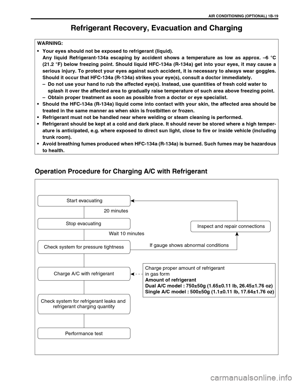
Operation Procedure for Charging A/C with Refrigerant
WARNING:
Your eyes should not be exposed to refrigerant (liquid).
Any liquid Refrigerant-134a escaping by accident shows a temperature as low as approx. –6 °C
(21.2 °F) below freezing point. Should liquid HFC-134a (R-134a) get into your eyes, it may cause a
serious injury. To protect your eyes against such accident, it is necessary to always wear goggles.
Should it occur that HFC-134a (R-134a) strikes your eye(s), consult a doctor immediately.
–Do not use your hand to rub the affected eye(s). Instead, use quantities of fresh cold water to
splash it over the affected area to gradually raise temperature of such area above freezing point.
–Obtain proper treatment as soon as possible from a doctor or eye specialist.
Should the HFC-134a (R-134a) liquid come into contact with your skin, the affected area should be
treated in the same manner as when skin is frostbitten or frozen.
Refrigerant must not be handled near where welding or steam cleaning is performed.
Refrigerant should be kept at a cold and dark place. It should never be stored where a high temper-
ature is anticipated, e.g. where exposed to direct sun light, close to fire or inside vehicle (including
trunk room).
Avoid breathing fumes produced when HFC-134a (R-134a) is burned. Such fumes may be hazardous
to health.
Start evacuating
Charge proper amount of refrigerant
in gas form
Amount of refrigerant
Dual A/C model : 750±50g (1.65±0.11 lb, 26.45±1.76 oz)
Single A/C model : 500±50g (1.1±0.11 lb, 17.64±1.76 oz)
Inspect and repair connections Stop evacuating
Performance test
Check system for pressure tightness
Charge A/C with refrigerant
Check system for refrigerant leaks and
refrigerant charging quantity
20 minutes
Wait 10 minutes
If gauge shows abnormal conditions
Page 49 of 656
1B-24 AIR CONDITIONING (OPTIONAL)
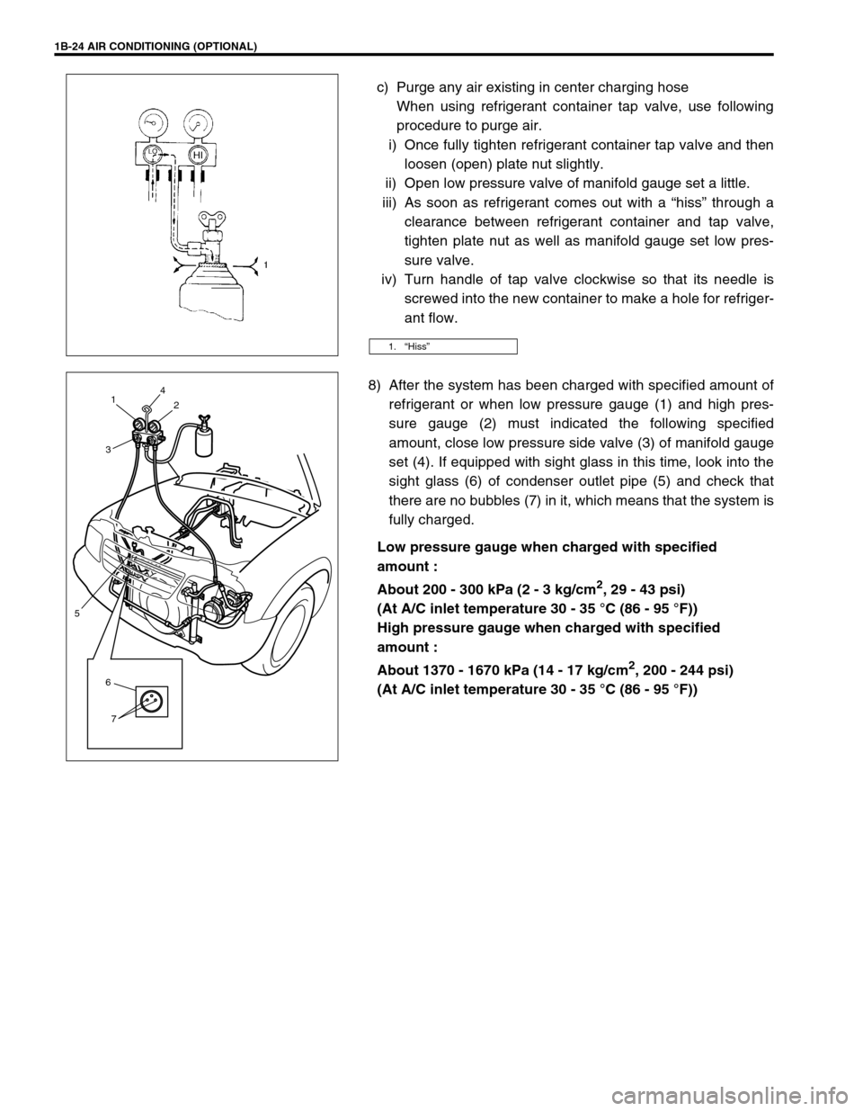
c) Purge any air existing in center charging hose
When using refrigerant container tap valve, use following
procedure to purge air.
i) Once fully tighten refrigerant container tap valve and then
loosen (open) plate nut slightly.
ii) Open low pressure valve of manifold gauge set a little.
iii) As soon as refrigerant comes out with a “hiss” through a
clearance between refrigerant container and tap valve,
tighten plate nut as well as manifold gauge set low pres-
sure valve.
iv) Turn handle of tap valve clockwise so that its needle is
screwed into the new container to make a hole for refriger-
ant flow.
8) After the system has been charged with specified amount of
refrigerant or when low pressure gauge (1) and high pres-
sure gauge (2) must indicated the following specified
amount, close low pressure side valve (3) of manifold gauge
set (4). If equipped with sight glass in this time, look into the
sight glass (6) of condenser outlet pipe (5) and check that
there are no bubbles (7) in it, which means that the system is
fully charged.
Low pressure gauge when charged with specified
amount :
About 200 - 300 kPa (2 - 3 kg/cm
2, 29 - 43 psi)
(At A/C inlet temperature 30 - 35 °C (86 - 95 °F))
High pressure gauge when charged with specified
amount :
About 1370 - 1670 kPa (14 - 17 kg/cm
2, 200 - 244 psi)
(At A/C inlet temperature 30 - 35 °C (86 - 95 °F))
1.“Hiss”
6
7
5
4
2 1
3
Page 51 of 656
1B-26 AIR CONDITIONING (OPTIONAL)
Never use heat for bending pipes. When bending a pipe, try to make its bending radius as slight as possible.
Keep internal parts of air conditioning free from moisture and dirt. When disconnecting any line from system,
install a blind plug or cap to the fitting immediately.
When tightening or loosening a fitting, use two wrenches, one for turning and the other for support.
Tighten flared nuts to specified torque.
Tightening torque
8 mm (0.31 in.) pipe : 13 N·m (1.3 kg-m, 9.5 lb-ft)
12.7 mm (0.5 in.) pipe : 22 N·m (2.2 kg-m, 16.0 lb-ft)
16 mm (0.63 in.) pipe : 33 N·m (3.3 kg-m, 24.0 lb-ft)
Route drain hose so that drained water does not make any contact to vehicle components.
Handling refrigerant HFC-134a (R-134a)
When handling refrigerant, always wear goggles to protect your eyes.
Avoid you direct contact to liquid refrigerant.
Do not heat refrigerant container higher than 40 °C (104 °F).
Do not discharge refrigerant into atmosphere.
Do not allow liquid refrigerant to touch bright metals. Refrigerant combined with moisture is corrosive and
will tarnish surfaces of bright metals including chrome.
After recovering refrigerant from system, the amount of compressor oil removed must be measured and the
same amount added to the system.
Refrigerant recovery
When discharging refrigerant out of A/C system, always recover it by using refrigerant recovery and recycling
equipment. Discharging refrigerant HFC-134a (R-134a) into atmosphere would cause adverse effect to environ-
ments.
Refrigerant charge
Charge a proper amount of refrigerant to A/C system according to charging procedure described in recovery,
evacuation and charging.NOTE:
When handling recovery and recycling equipment, be sure to follow the instruction manual for the
equipment.
CAUTION:
Do not perform an additional refrigerant charging to A/C system. This cause it to overcharge.
Page 165 of 656
6-1-4 ENGINE GENERAL INFORMATION AND DIAGNOSIS (H27 ENGINE)
When disconnecting couplers, don’t pull wire harness but
make sure to hold coupler itself. With lock type coupler, be
sure to unlock before disconnection. Attempt to disconnect
coupler without unlocking may result in damage to coupler.
When connecting lock type coupler, insert it till clicking
sound is heard and connect it securely.
Precaution on Fuel System Service
Work must be done with no smoking, in a well-ventilated area and away from any open flames.
As fuel feed line (between fuel pump and fuel pressure regulator) is still under high fuel pressure even after
engine was stopped, loosening or disconnecting fuel feed line directly may cause dangerous spout of fuel to
occur where loosened or disconnected. Before loosening or disconnecting fuel feed line, make sure to
release fuel pressure according to “FUEL PRESSURE RELIEF PROCEDURE” in this section.
A small amount of fuel may be released after the fuel line is disconnected.
In order to reduce the chance of personal injury, cover the fitting to be disconnected with a shop cloth. Put
that cloth in an approved container when disconnection is completed.
Never run engine with fuel pump relay disconnected when engine and exhaust system are hot.
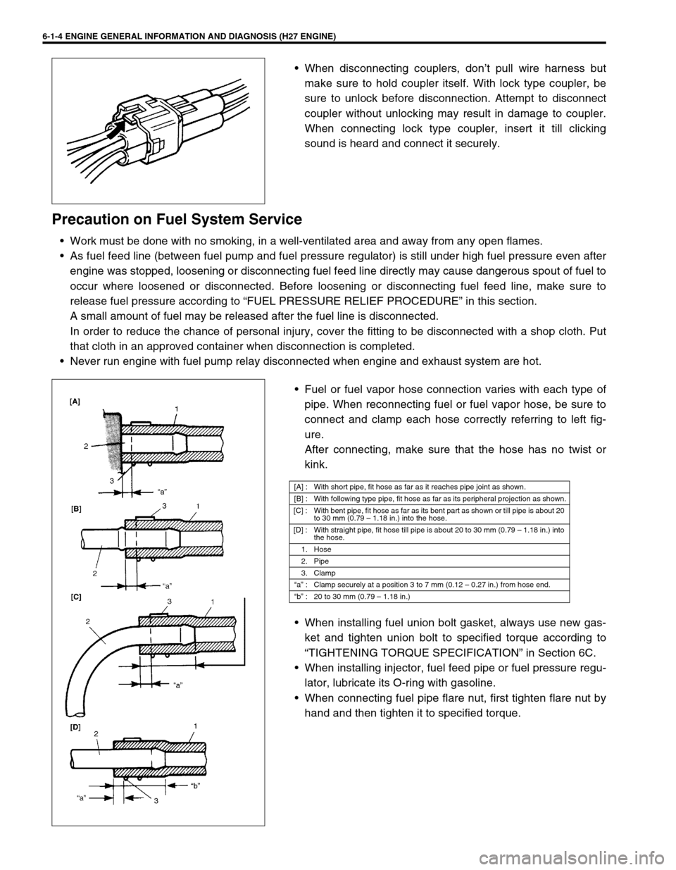
Fuel or fuel vapor hose connection varies with each type of
pipe. When reconnecting fuel or fuel vapor hose, be sure to
connect and clamp each hose correctly referring to left fig-
ure.
After connecting, make sure that the hose has no twist or
kink.
When installing fuel union bolt gasket, always use new gas-
ket and tighten union bolt to specified torque according to
“TIGHTENING TORQUE SPECIFICATION” in Section 6C.
When installing injector, fuel feed pipe or fuel pressure regu-
lator, lubricate its O-ring with gasoline.
When connecting fuel pipe flare nut, first tighten flare nut by
hand and then tighten it to specified torque.
[A] : With short pipe, fit hose as far as it reaches pipe joint as shown.
[B] : With following type pipe, fit hose as far as its peripheral projection as shown.
[C] : With bent pipe, fit hose as far as its bent part as shown or till pipe is about 20
to 30 mm (0.79 – 1.18 in.) into the hose.
[D] : With straight pipe, fit hose till pipe is about 20 to 30 mm (0.79 – 1.18 in.) into
the hose.
1. Hose
2. Pipe
3. Clamp
“a” : Clamp securely at a position 3 to 7 mm (0.12 – 0.27 in.) from hose end.
“b” : 20 to 30 mm (0.79 – 1.18 in.)
Page 190 of 656
ENGINE GENERAL INFORMATION AND DIAGNOSIS (H27 ENGINE) 6-1-29
EGR VALVE (%)
This parameter indicates opening rate of EGR valve which controls the amount of EGR flow.
A/C SWITCH (ON/OFF)
ON : Command for operation being output from A/C amplifier to compressor.
OFF : Command for operation not being output.
PSP SWITCH (ON/OFF)
ON : PSP switch detects P/S operation. (high P/S pressure)
OFF : PSP switch not detects P/S operation.
PNP SIGNAL (Transmission Range Switch, P/N or D range)
Whether the transmission range switch (P/N position switch) at P or N range or at R, D, 2 or L range is displayed.
If at P or N range, “P/N range” is displayed and if at R, D, 2 or L range, “D range” is displayed.
FUEL TANK LEVEL (%)
This parameter indicates approximate fuel level in the fuel tank. As the detectable range of the fuel level sensor
is set as 0 to 100 %, however, with some models whose fuel tank capacity is smaller, the indicated fuel level may
be only 70 % even when the fuel tank is full.
ELECTRIC LOAD (ON/OFF)
ON : Small light switch ON or rear window defogger switch ON.
OFF : Small light switch OFF and rear window defogger switch OFF.
VSS (4-A/T) (km/h, MPH)
It is computed by using pulse signals from vehicle speed sensor on 4-speed automatic transmission.
THROT POS LEVEL (Throttle Position Level For 4-A/T, “0”, “1”, “2”, “3”, “4”,“5”,“6” or “7”)
This parameter indicates which level (zone) the throttle valve opening is in.
The throttle opening is divided into 8 levels (zones) from “0” (about idle position) to “7” (about full open) and sig-
nals are assigned to each opening level (zone). PCM controls the automatic gear change of the automatic trans-
mission by using these signals according to the signal from the TP sensor.
GEAR POSITION (1ST, 2ND, 3RD or 4TH)
The gear position is determined on the basis of the command state signals generated from PCM to shift sole-
noids A and B (#1 and #2) and displayed as shown in the table below.
SHIFT SOL #1 CON/MON (Shift Solenoid #1, A Command/monitor, ON/OFF)
CON-ON : ON command being output to shift solenoid #1, A.
CON-OFF : ON command not being output.
MON-ON : Electricity being passed to shift solenoid #1, A.
MON-OFF : Electricity not being passed.SHIFT SOLENOID-A SHIFT SOLENOID-B
DISPLAY1ST ON OFF
2ND ON ON
3RD OFF ON
4TH OFF OFF
Page 340 of 656
ENGINE AND EMISSION CONTROL SYSTEM (SEQUENTIAL MULTIPORT FUEL INJECTION FOR H27 ENGINE) 6E2-7
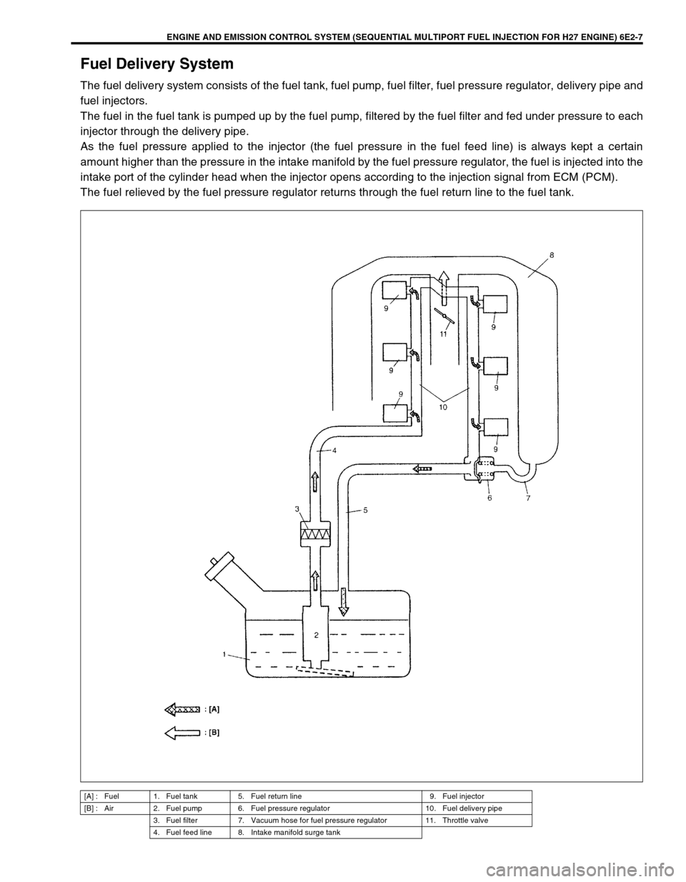
Fuel Delivery System
The fuel delivery system consists of the fuel tank, fuel pump, fuel filter, fuel pressure regulator, delivery pipe and
fuel injectors.
The fuel in the fuel tank is pumped up by the fuel pump, filtered by the fuel filter and fed under pressure to each
injector through the delivery pipe.
As the fuel pressure applied to the injector (the fuel pressure in the fuel feed line) is always kept a certain
amount higher than the pressure in the intake manifold by the fuel pressure regulator, the fuel is injected into the
intake port of the cylinder head when the injector opens according to the injection signal from ECM (PCM).
The fuel relieved by the fuel pressure regulator returns through the fuel return line to the fuel tank.
[A] : Fuel 1. Fuel tank 5. Fuel return line 9. Fuel injector
[B] : Air 2. Fuel pump 6. Fuel pressure regulator 10. Fuel delivery pipe
3. Fuel filter 7. Vacuum hose for fuel pressure regulator 11. Throttle valve
4. Fuel feed line 8. Intake manifold surge tank
Page 489 of 656
7F-4 DIFFERENTIAL (REAR)
Precaution for Maintenance Service
•When having driven through water, check immediately if
water has entered (if so, oil is cloudy). Water mixed oil must
be changed at once.
•Whenever vehicle is hoisted for any other service work than
oil change, also be sure to check for oil leakage and status of
breather hoses.
Differential Gear Oil Change
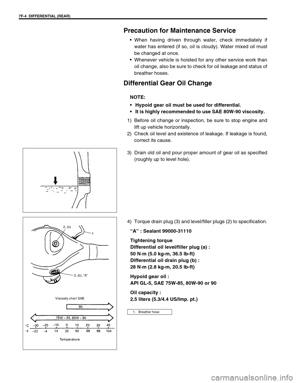
1) Before oil change or inspection, be sure to stop engine and
lift up vehicle horizontally.
2) Check oil level and existence of leakage. If leakage is found,
correct its cause.
3) Drain old oil and pour proper amount of gear oil as specified
(roughly up to level hole).
4) Torque drain plug (3) and level/filler plugs (2) to specification.
“A” : Sealant 99000-31110
Tightening torque
Differential oil level/filler plug (a) :
50 N·m (5.0 kg-m, 36.5 lb-ft)
Differential oil drain plug (b) :
28 N·m (2.8 kg-m, 20.5 lb-ft)
Hypoid gear oil :
API GL-5, SAE 75W-85, 80W-90 or 90
Oil capacity :
2.5 liters (5.3/4.4 US/Imp. pt.) NOTE:
Hypoid gear oil must be used for differential.
It is highly recommended to use SAE 80W-90 viscosity.
1. Breather hose