service SUZUKI GRAND VITARA 2007 3.G User Guide
[x] Cancel search | Manufacturer: SUZUKI, Model Year: 2007, Model line: GRAND VITARA, Model: SUZUKI GRAND VITARA 2007 3.GPages: 211, PDF Size: 3.21 MB
Page 66 of 211
Downloaded from www.Manualslib.com manuals search engine 4-4 INSTRUMENT PANEL
66J21-03E
inflation pressure as specified in the vehi-
cle placard and owner’s manual.
The low tire pressure warning light is also
used to inform you of a TPMS malfunction.
When the system detects a malfunction,
this light will flash for approximately one
minute and then remain continuously illu-
minated. This sequence will be repeated
approximately ten minutes after subse-
quent vehicle start-ups as long as the mal-
function exists.
NOTE:
The low tire pressure warning light may not
come on immediately if you have a sudden
loss of air pressure.
Refer to “Tire Pressure Monitoring System”
in the “OPERATING YOUR VEHICLE”
section for additional details on the tire
pressure monitoring system. Refer to
“Tires” in the “INSPECTION AND MAIN-
TENANCE” section for information on
maintaining proper tire pressure.
WARNING
If the low tire pressure warning light
does not come on when the ignition
is turned to the “ON” position, or
comes on and blinks while driving
there may be a problem with the tire
pressure monitoring system. Have
your vehicle inspected by an autho-
rized SUZUKI dealer. Even if the light
turns off after blinking, indicating
that the monitoring system has
recovered, make sure to have an
authorized SUZUKI dealer check the
system.
WARNING
The load rating of your tires is
reduced at lower inflation pressures.
If your tires become even moderately
under-inflated, the vehicle load may
exceed the load rating of the tires,
which can lead to tire failure. The low
tire pressure warning light will not
alert you of this condition. The warn-
ing light will only come on when one
or more of your tires become signifi-
cantly under-inflated. Check and
adjust your tire inflation pressure at
least once a month. Refer to “Tires”
in the “INSPECTION AND MAINTE-
NANCE” section.
WARNING
If the low tire pressure warning light
comes on and stays on, reduce your
speed and avoid abrupt steering and
braking. Stop in a safe place as soon
as possible and check your tires.
If you have a flat tire, replace it with
the spare tire. Refer to “Jacking
Instructions” in the “EMERGENCY
SERVICE” section. Refer to
“Replacing Tires and/or Wheels”
for instructions on how to restore
normal operation of the tire pres-
sure monitoring system after you
have had a flat tire.
(Continued)
WARNING
(Continued)
If one or more of your tires is
under-inflated, adjust the inflation
pressure in all of your tires to the
recommended inflation pressure as
soon as possible.
Be aware that driving on a signifi-
cantly under-inflated tire can cause
the tire to overheat and can lead to
tire failure, and may affect steering
control and brake effectiveness. This
could lead to an accident, resulting in
severe injury or death.
Warning and Indicator Lights: 8
Page 70 of 211
Downloaded from www.Manualslib.com manuals search engine 4-8 INSTRUMENT PANEL
66J21-03E
“AIR BAG” Light
63J030
This light monitors inflators, crash sensors,
seat belt pretensioners, the front passen-
ger sensing system, and corresponding
electrical circuits.
This light blinks for several seconds when
the ignition switch is turned to the “ON”
position so you can check if the light is
working. The light will come on and stay on
if there is a problem in the air bag system
or the seat belt pretensioner system.
Malfunction Indicator Light
65D530
Your vehicle has a computer-controlled
emission control system. A malfunction
indicator light is provided on the instrument
panel to indicate when it is necessary to
have the emission control system serviced.
The malfunction indicator light comes on
when the ignition switch is turned to the
“ON” position to let you know the light is
working and goes out when the engine is
started.
If the malfunction indicator light comes on
or blinks when the engine is running, ser-
vice to the emission control system is nec-
essary. Bring the vehicle to your SUZUKI
dealer to have the emission control system
serviced right away and avoid hard accel-
eration until the service is performed.NOTE:
If the fuel filler cap is not installed fully, the
electrical system gets wet (such as by driv-
ing through a deep puddle of water) or the
fuel tank gets nearly empty, the malfunc-
tion indicator lamp may come on. If so, the
lamp will go off after driving a few times
after the fuel filler cap is installed fully, the
electrical system dries out or the fuel tank
is filled.
WARNING
If the “AIR BAG” light does not blink
when the ignition switch is turned to
the “ON” position or stays on or
comes on when driving, the air bag
system or the seat belt pretensioner
system (if equipped) may not work
properly. Have both systems
inspected by an authorized SUZUKI
dealer.
CAUTION
Continuing to drive the vehicle when
the malfunction indicator light is on
or blinking can cause permanent
damage to the vehicle’s emission
control system, and can affect fuel
economy and driveability.
Warning and Indicator Lights: 8
Page 74 of 211

Downloaded from www.Manualslib.com manuals search engine 4-12 INSTRUMENT PANEL
66J21-03E
64J049
When the ignition switch is turned to the
“ON” position, the display shows the
odometer or trip meter.
The display shows three types of indica-
tion; odometer, trip meter A and trip meter
B. Push the selector knob (3) quickly to
switch the indication among the three.
You can use the two trip meters (A and B)
independently.
64J205
Hold in the selector knob for about 2 sec-
onds to reset the trip meter to zero.
Brightness Control
66J213
(3) Brightness control knob
(4) In this position, the meter lights are
the dimmest and the other instrument
panel lights are turned off.
(5) In this position, the instrument panel
lights are the brightest.
Your vehicle has a system to automatically
dim the instrument panel lights when the
ignition switch is in the “ON” position and
the lighting switch is either (a) turned to the
second or third position, or (b) turned to
the “AUTO” position and it is dark around
the light sensor. The level of brightness
depends on the position of the brightness
control knob (3).
To reduce the brightness and activate the
automatic dimming feature, turn the knob
(3) counterclockwise. When the knob (3) is
turned counterclockwise to position (4), the
CAUTION
Keep track of your odometer reading
and check the maintenance sched-
ule regularly for required services.
Increased wear or damage to certain
parts can result from failure to per-
form required services at the proper
mileage intervals.
(3) (A) (B)
(C)
About 2 seconds
(3)
(3)
(5) (4)
EXAMPLE
Speedometer/Odometer/Trip meter/Meter Illumination
Control: 8
Page 92 of 211

Downloaded from www.Manualslib.com manuals search engine 4-30 INSTRUMENT PANEL
66J21-03E
Precautions When the inside of the car is very cold
and the player is used soon after switch-
ing on the heater, moisture may form on
the disc or the optical parts of the player
and proper playback may not be possi-
ble. If moisture forms on the disc, wipe it
off with a soft cloth. If moisture forms on
the optical parts of the player, do not use
the player for about one hour, this will
allow the condensation to disappear nor-
mally.
Driving on extremely bumpy roads which
cause severe vibrations may cause
sound to skip.
This unit uses a precision mechanism.
Even in the event that trouble arises,
never open the case, disassemble the
unit, or lubricate the rotating parts.
Please bring the unit to an authorized
SUZUKI dealer or a Clarion service
Department.
Cautions on Handling
52D274
This unit has been designed specifically for
playback of compact discs bearing the
mark (A).
No other discs can be played.
52D275
To remove the compact disc from its stor-
age case, press down on the center of the
case and lift the disc out, holding it care-
fully by the edges.
Always handle the compact disc by the
edges.Never touch the surface.
52D347
To remove fingermarks and dust, use a
soft cloth, and wipe in a straight line from
the center of the compact disc to the cir-
cumference.
52D277
New discs may have some roughness
around the edges. The unit may not work
or the sound may skip if such discs are
used. Use a ball-point pen (B), etc. to
remove the roughness (C) from edges of
the disc before insertion inside the unit.
(A)
Removing the disc Proper way to hold
the compact disc
(B)
(B)
(C)
Audio Systems:
Page 106 of 211

Downloaded from www.Manualslib.com manuals search engine 4-44 INSTRUMENT PANEL
66J21-03E
Listening to a XM Satellite Radio (Option)
66J219
(5)(2)
(8)
(6)
(3)
(4)
(7)
(1)(5)(2)
(8)
(6)
(3)
(4)
(7)
(1)
Type 1 AM/FM/XM CD PLAYER WITH CD CHANGER CONTROL
Type 2 AM/FM/XM 6-CD PLAYER WITH CD CHANGER CONTROL
Display
66J107
(1) XM button
(2) Category button (CAT)
(3) Seek up button
(4) Seek down button
(5) Manual tuning knob
(6) Display button (DISP)
(7) Preset button (1 to 6)
(8) Scan button (SCAN)
(A) Band
(B) Channel number
(C) Category indicator
If you want to purchase XM Satellite Radio
Service, contact your SUZUKI dealer.
It is necessary to buy a special tuner to
receive XM broadcasting.
Your vehicle is capable of receiving XM
Satellite Radio anywhere in the United
States except Hawaii, Alaska, and Can-
ada.
(A)
(B) (C)
Audio Systems:
Page 132 of 211
Downloaded from www.Manualslib.com manuals search engine 8-6 VEHICLE LOADING AND TOWING
66J21-03E
60A186
WARNING
(Continued)
Avoid “riding” the brakes. “Riding”
the brakes could cause the brakes
to overheat, resulting in reduced
braking efficiency. Use engine
braking as much as possible.
Because of the added trailer
weight, your engine may overheat
on hot days when going up long or
steep hills. Pay attention to your
engine temperature gauge. If it indi-
cates overheating, pull off the road
and stop in a safe place. Refer to
the “If the Engine Overheats” in
“EMERGENCY SERVICE” section
for details on how to proceed.
WARNING
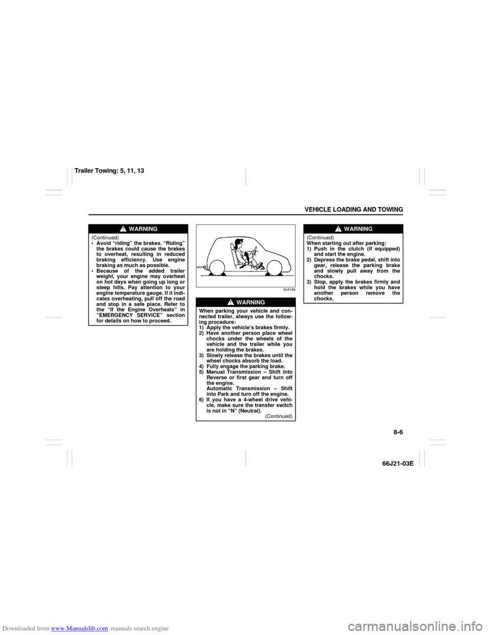
When parking your vehicle and con-
nected trailer, always use the follow-
ing procedure:
1) Apply the vehicle’s brakes firmly.
2) Have another person place wheel
chocks under the wheels of the
vehicle and the trailer while you
are holding the brakes.
3) Slowly release the brakes until the
wheel chocks absorb the load.
4) Fully engage the parking brake.
5) Manual Transmission – Shift into
Reverse or first gear and turn off
the engine.
Automatic Transmission – Shift
into Park and turn off the engine.
6) If you have a 4-wheel drive vehi-
cle, make sure the transfer switch
is not in “N” (Neutral).
(Continued)
WARNING
(Continued)
When starting out after parking:
1) Push in the clutch (if equipped)
and start the engine.
2) Depress the brake pedal, shift into
gear, release the parking brake
and slowly pull away from the
chocks.
3) Stop, apply the brakes firmly and
hold the brakes while you have
another person remove the
chocks.
Trailer Towing: 5, 11, 13
Page 139 of 211
Downloaded from www.Manualslib.com manuals search engine 9-1 INSPECTION AND MAINTENANCE
66J21-03E
60A187S
WARNING
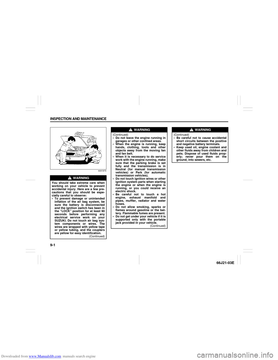
You should take extreme care when
working on your vehicle to prevent
accidental injury. Here are a few pre-
cautions that you should be espe-
cially careful to observe:
To prevent damage or unintended
inflation of the air bag system, be
sure the battery is disconnected
and the ignition switch has been in
the “LOCK” position for at least 90
seconds before performing any
electrical service work on your
SUZUKI. Do not touch air bag sys-
tem components or wires. The
wires are wrapped with yellow tape
or yellow tubing, and the couplers
are yellow for easy identification.
(Continued)
WARNING
(Continued)
Do not leave the engine running in
garages or other confined areas.
When the engine is running, keep
hands, clothing, tools and other
objects away from the moving fan
and fan belt.
When it is necessary to do service
work with the engine running, make
sure that the parking brake is set
fully and the transmission is in
Neutral (for manual transmission
vehicles) or Park (for automatic
transmission vehicles).
Do not touch ignition wires or other
ignition system parts when starting
the engine or when the engine is
running, or you could receive an
electric shock.
Be careful not to touch a hot
engine, exhaust manifold and
pipes, muffler, radiator and water
hoses.
Do not allow smoking, sparks or
flames around gasoline or the bat-
tery. Flammable fumes are present.
Do not get under your vehicle if it is
supported only with the portable
jack provided in your vehicle.
(Continued)
WARNING
(Continued)
Be careful not to cause accidental
short circuits between the positive
and negative battery terminals.
Keep used oil, engine coolant and
other fluids away from children and
pets. Dispose of used fluids prop-
erly; never pour them on the
ground, into sewers, etc.
Page 140 of 211
Downloaded from www.Manualslib.com manuals search engine 9-2 INSPECTION AND MAINTENANCE
66J21-03E
NOTICE (for U.S.A.)
Maintenance, replacement or repair of
the emission control devices and sys-
tems may be performed by any automo-
bile repair establishment or individual
using any part which has been certified
under the provisions in the Clean Air
Act sec. 207. (a) (2).
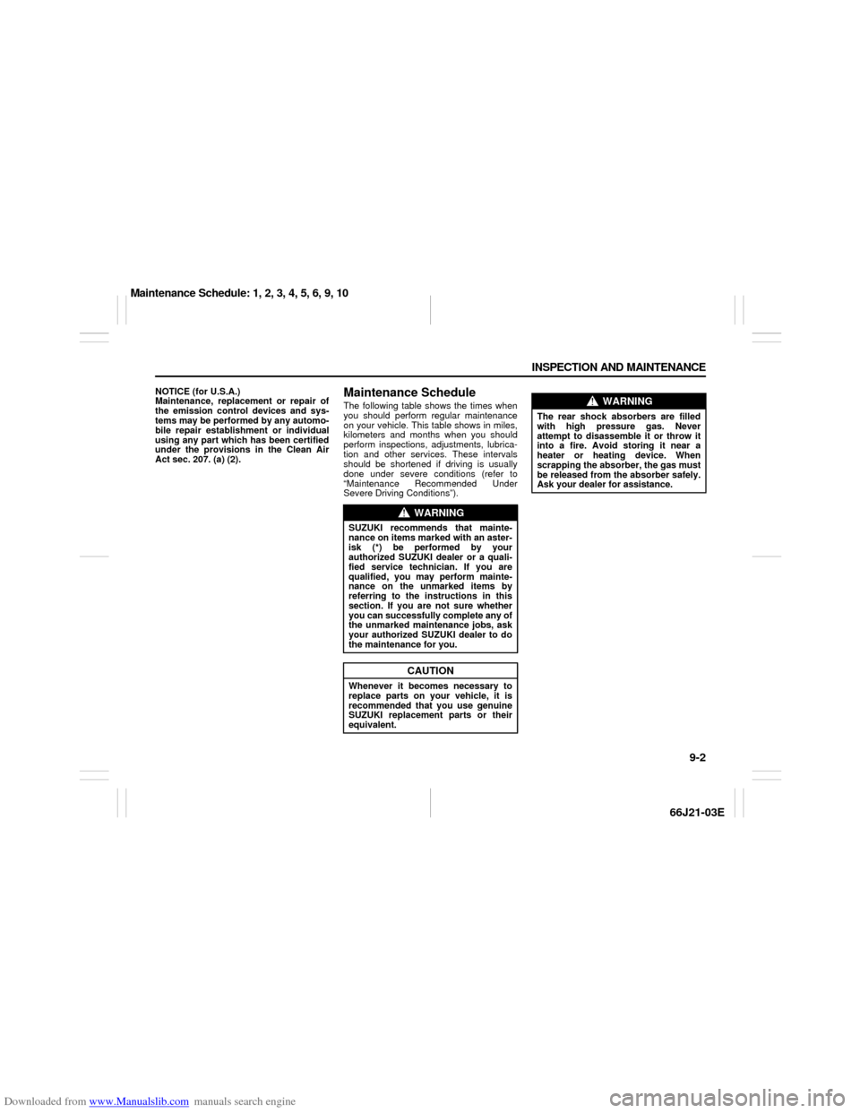
Maintenance ScheduleThe following table shows the times when
you should perform regular maintenance
on your vehicle. This table shows in miles,
kilometers and months when you should
perform inspections, adjustments, lubrica-
tion and other services. These intervals
should be shortened if driving is usually
done under severe conditions (refer to
“Maintenance Recommended Under
Severe Driving Conditions”).
WARNING
SUZUKI recommends that mainte-
nance on items marked with an aster-
isk (*) be performed by your
authorized SUZUKI dealer or a quali-
fied service technician. If you are
qualified, you may perform mainte-
nance on the unmarked items by
referring to the instructions in this
section. If you are not sure whether
you can successfully complete any of
the unmarked maintenance jobs, ask
your authorized SUZUKI dealer to do
the maintenance for you.
CAUTION
Whenever it becomes necessary to
replace parts on your vehicle, it is
recommended that you use genuine
SUZUKI replacement parts or their
equivalent.
WARNING
The rear shock absorbers are filled
with high pressure gas. Never
attempt to disassemble it or throw it
into a fire. Avoid storing it near a
heater or heating device. When
scrapping the absorber, the gas must
be released from the absorber safely.
Ask your dealer for assistance.
Maintenance Schedule: 1, 2, 3, 4, 5, 6, 9, 10
Page 142 of 211
Downloaded from www.Manualslib.com manuals search engine 9-4 INSPECTION AND MAINTENANCE
66J21-03E
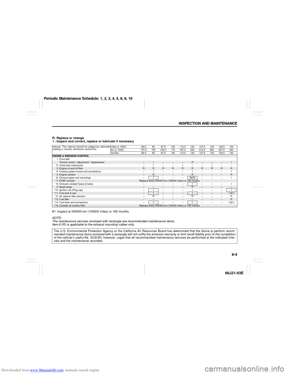
R: Replace or change
I : Inspect and correct, replace or lubricate if necessary
#1: Inspect at 250000 km (150000 miles) or 180 months.
NOTE:
The maintenance services enclosed with rectangle are recommended maintenance items.
Item 6 (R) is applicable to the exhaust mounting rubber only.Interval: This interval should be judged by odometer
reading or months, whichever comes first.miles (x 1000) 82.5 90 97.5 105 112.5 120 127.5 135 142.5 150
km (x 1000) 137.5 150 162.5 175 187.5 200 212.5 225 237.5 250
months 82.5 90 97.5 105 112.5 120 127.5 135 142.5 150ENGINE & EMISSION CONTROL
1. Drive beltTension check, *adjustment, *replacement
–
I
–
–
–
R
–
–
–
I
*2. Valve lash (clearance) – I – – I – – I – –3.Engine oil and oil filter
R
R
R
R
R
R
R
R
R
R
*4. Cooling system hoses and connections – I – – – I – – – I5.Engine coolant
–
R
–
–
–
R
–
–
–
R
*6. Exhaust pipes and mountings – I – – – I&(R) – – – I*7.
EVAP canister
Replace every 250000 km (150000 miles) or 180 months
*8. Emission-related hoses & tubes – – – – – I – – – I9.Spark plugs
–
–
–
–
–
R
–
–
–
–
*10. Ignition coil (Plug cap) – I – – – I – – – I*11.
Fuel tank & cap
–
I
–
–
–
I
–
–
–
I (#1)
12. Air cleaner filter element – R – – – R – – – R*13.
Fuel filter
–
–
–
–
–
–
–
–
–
R
*14. Fuel lines and connections – I – – – I – – – I (#1)*15.
Canister air suction filter
Replace every 250000 km (150000 miles) or 180 months
The U.S. Environmental Protection Agency or the California Air Resources Board has determined that the failure to perform recom-
mended maintenance items enclosed with a rectangle will not nullify the emission warranty or limit recall liability prior to the completion
of the vehicle’s useful life. SUZUKI, however, urges that all recommended maintenance services be performed at the indicated inter-
vals and the maintenance recorded.
Periodic Maintenance Schedule: 1, 2, 3, 4, 5, 6, 9, 10
Page 144 of 211
Downloaded from www.Manualslib.com manuals search engine 9-6 INSPECTION AND MAINTENANCE
66J21-03E
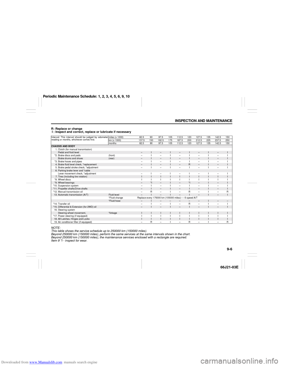
R: Replace or change
I : Inspect and correct, replace or lubricate if necessary
NOTE:
This table shows the service schedule up to 250000 km (150000 miles).
Beyond 250000 km (150000 miles), perform the same services at the same intervals shown in the chart.
Beyond 250000 km (150000 miles), the maintenance services enclosed with a rectangle are required.
Item 9 *I - inspect for wear.Interval: This interval should be judged by odometer
reading or months, whichever comes first.miles (x 1000) 82.5 90 97.5 105112.5 120 127.5 135 142.5 150
km (x 1000) 137.5 150 162.5 175 187.5 200 212.5 225 237.5 250
months 82.5 90 97.5 105 112.5 120 127.5 135 142.5 150CHASSIS AND BODY
1. Clutch (for manual transmission)
Pedal and fluid level
–
I
–
I
–
I
–
I
–
I
*2. Brake discs and pads (front) – I – I – I – I – I
Brake drums and shoes
(rear)
–
I
–
I
–
I
–
I
–
I
*3. Brake hoses and pipes – I – I – I – I – I
4.Brake fluid level check, *replacement
–
I
–
I
–
R
–
I
–
I
5. Brake pedal stroke check, *adjustment – I – I – I – I – I
6.Parking brake lever and *cableLever movement check, *adjustment –I–I–I–I–I7.Tires (including tire rotation)
I
I
I
I
I
I
I
I
I
I
*8.Wheel discs IIIIIIIIII
*9.
Wheel bearings
–
*I
–
I
–
*I
–
I
–
I
*10. Suspension system – I – I – I – I – I
*11.
Propeller shafts/Drive shafts
–
I
–
I
–
I
–
I
–
I
*12. Manual transmission oil – R – I – R – I – R
13.
Automatic transmission (A/T)
Fluid level
–
I
–
I
–
I
–
I
–
I
*Fluid change Replace every 175000 km (105000 miles)-----5-speed A/T
*Fluid hose
–
I
–
–
–
–
–
I
–
–
*14. Transfer oil – I – I – R – I – I
*15.
Differential & Extension (for 2WD) oil
–
I
–
I
–
I
–
I
–
I
16. Steering system
Steering wheel movement,
*linkage
I
I
I
I
I
I
I
I
I
I
*17. Power steering (if equipped) I I I I I I I I I I
18.
All Latches, Hinges and Locks
I
I
I
I
I
I
I
I
I
I
19. Air conditioner filter (if equipped) – R – I – R – I – R
Periodic Maintenance Schedule: 1, 2, 3, 4, 5, 6, 9, 10