brake SUZUKI GRAND VITARA 2007 3.G Owner's Manual
[x] Cancel search | Manufacturer: SUZUKI, Model Year: 2007, Model line: GRAND VITARA, Model: SUZUKI GRAND VITARA 2007 3.GPages: 211, PDF Size: 3.21 MB
Page 145 of 211
Downloaded from www.Manualslib.com manuals search engine 9-7 INSPECTION AND MAINTENANCE
66J21-03E
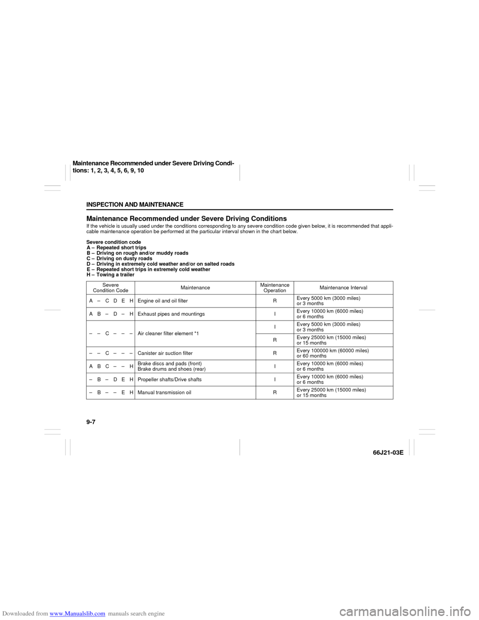
Maintenance Recommended under Severe Driving ConditionsIf the vehicle is usually used under the conditions corresponding to any severe condition code given below, it is recommended that appli-
cable maintenance operation be performed at the particular interval shown in the chart below.
Severe condition code
A – Repeated short trips
B – Driving on rough and/or muddy roads
C – Driving on dusty roads
D – Driving in extremely cold weather and/or on salted roads
E – Repeated short trips in extremely cold weather
H – Towing a trailer
Severe
Condition CodeMaintenanceMaintenance
OperationMaintenance Interval
A – C D E H Engine oil and oil filter REvery 5000 km (3000 miles)
or 3 months
A B – D – H Exhaust pipes and mountings IEvery 10000 km (6000 miles)
or 6 months
– – C – – – Air cleaner filter element *1IEvery 5000 km (3000 miles)
or 3 months
REvery 25000 km (15000 miles)
or 15 months
– – C – – – Canister air suction filter REvery 100000 km (60000 miles)
or 60 months
ABC– – HBrake discs and pads (front)
Brake drums and shoes (rear)IEvery 10000 km (6000 miles)
or 6 months
– B – D E H Propeller shafts/Drive shafts IEvery 10000 km (6000 miles)
or 6 months
– B – – E H Manual transmission oil REvery 25000 km (15000 miles)
or 15 months
Maintenance Recommended under Severe Driving Condi-
tions: 1, 2, 3, 4, 5, 6, 9, 10
Page 152 of 211

Downloaded from www.Manualslib.com manuals search engine 9-14 INSPECTION AND MAINTENANCE
66J21-03E
Extension case (2WD)
66J165
(1) Oil filler and level plug
(2) Oil drain plugFront differential
66J006
Rear differential
66J007
(1) Oil filler and level plug
(2) Oil drain plug
Gear Oil Level CheckThe manual transmission, transfer gears,
extension case and differentials (front and
rear) are lubricated with gear oil. To check
the gear oil level in any of the above loca-
tions, use the following procedure:
1) Park the vehicle on a level surface. Set
parking brake and stop the engine.
2) Remove the oil filler plug (1).
3) Check the inside of the hole with your
finger. If the oil level comes up to the
bottom of the plug hole, the oil level is
correct. If so, reinstall the plug.
4) If the oil level is low, add gear oil
through the filler plug hole (1) until the
oil level reaches the bottom of the filler
hole, then reinstall the plug.
(2)(1)
(1)
(2)
(1)
(2)
Gear Oil: 6, 10
Automatic Transmission Fluid: 10
Page 154 of 211

Downloaded from www.Manualslib.com manuals search engine 9-16 INSPECTION AND MAINTENANCE
66J21-03E
NOTE:
Do not check the fluid level if you have just
driven the vehicle for a long time at high
speed, if you have driven in city traffic in
hot weather, or if the vehicle has been pull-
ing a trailer. Wait until the fluid cools down
(about 30 minutes), or the fluid level indica-
tion will not be correct.
3) Park your vehicle on level ground.
4) Apply the parking brake and then start
the engine in “P” (Park). Let it idle for
two minutes and keep it running during
the fluid level check.
5) With your foot on the brake pedal, move
the gearshift lever through each gear,
pausing for about three seconds in
each range. Then move it back to the
“P” (Park) position.
52D032
The handle of the A/T fluid dipstick is col-
ored red for easy identification.
65D109
6) Remove the dipstick, clean it and push
it back in until the cap seats. Pull out
the dipstick and read the fluid level. The fluid level should be between the
two marks in the “HOT” range on the
dipstick.
7) Add just enough specified fluid through
the dipstick hole to fill the transmission
to the proper level.
Changing OilSince special procedures, materials and
tools are required to change the automatic
transmission oil, it is recommended that
you trust this job to your authorized
SUZUKI dealer.
WARNING
Be sure to depress the brake pedal
when moving the gearshift lever, or
the vehicle can move suddenly.
FULL HOT
LOW HOT
CAUTION
After checking or adding oil, be sure
to insert the dipstick securely.
Engine Coolant: 1, 2
Page 157 of 211
Downloaded from www.Manualslib.com manuals search engine 9-19 INSPECTION AND MAINTENANCE
66J21-03E
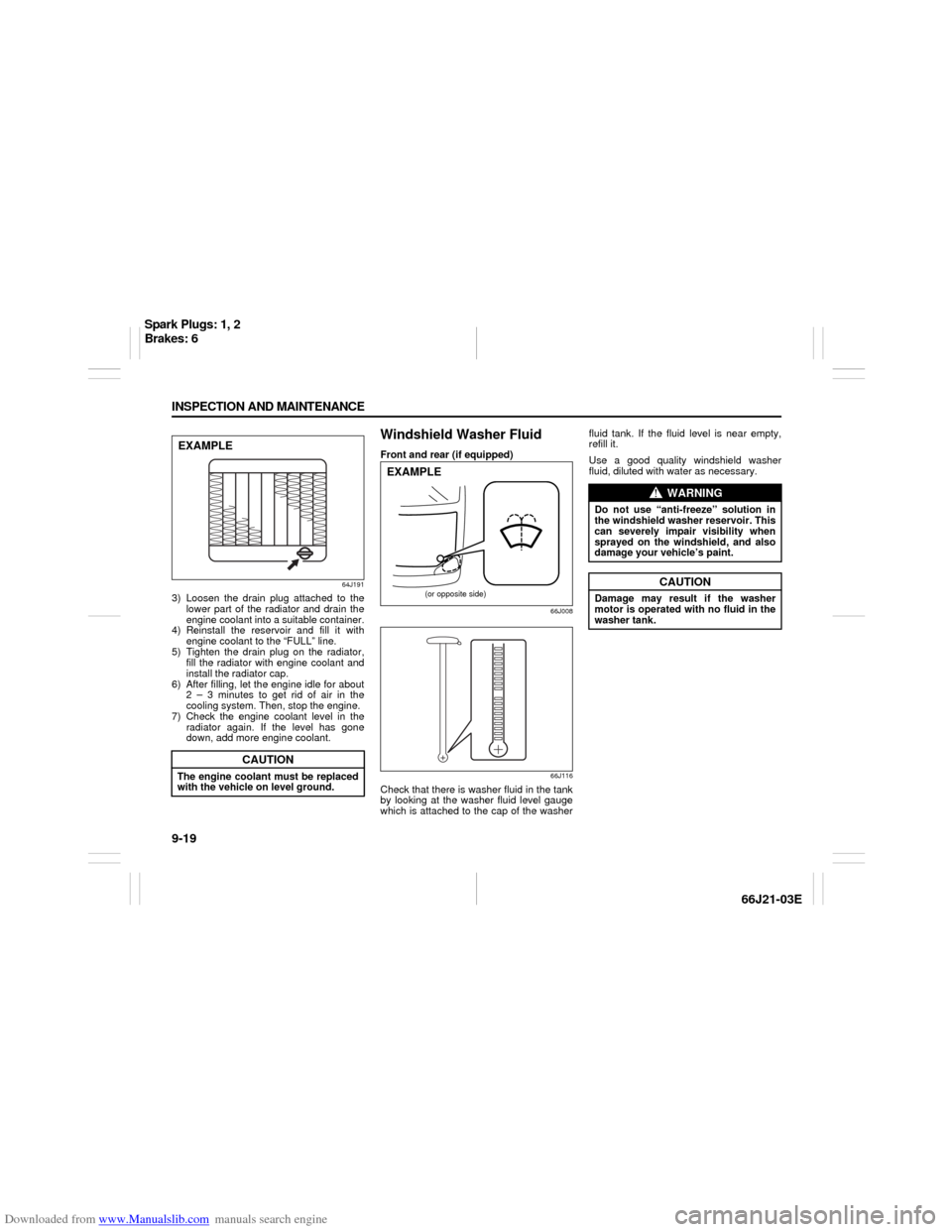
64J191
3) Loosen the drain plug attached to the
lower part of the radiator and drain the
engine coolant into a suitable container.
4) Reinstall the reservoir and fill it with
engine coolant to the “FULL” line.
5) Tighten the drain plug on the radiator,
fill the radiator with engine coolant and
install the radiator cap.
6) After filling, let the engine idle for about
2 – 3 minutes to get rid of air in the
cooling system. Then, stop the engine.
7) Check the engine coolant level in the
radiator again. If the level has gone
down, add more engine coolant.
Windshield Washer FluidFront and rear (if equipped)
66J008
66J116
Check that there is washer fluid in the tank
by looking at the washer fluid level gauge
which is attached to the cap of the washerfluid tank. If the fluid level is near empty,
refill it.
Use a good quality windshield washer
fluid, diluted with water as necessary.
CAUTION
The engine coolant must be replaced
with the vehicle on level ground.EXAMPLE
(or opposite side)
EXAMPLE
WARNING
Do not use “anti-freeze” solution in
the windshield washer reservoir. This
can severely impair visibility when
sprayed on the windshield, and also
damage your vehicle’s paint.
CAUTION
Damage may result if the washer
motor is operated with no fluid in the
washer tank.
Spark Plugs: 1, 2
Brakes: 6
Page 158 of 211

Downloaded from www.Manualslib.com manuals search engine 9-20 INSPECTION AND MAINTENANCE
66J21-03E
Air Cleaner
66J167
If the air cleaner is clogged with dust, there
will be greater intake resistance, resulting
in decreased power output and increased
fuel consumption.
Check and clean periodically according to
the following procedure:
1) Take off the air cleaner case cover.
Remove the element from the air
cleaner case cover.
2) This air cleaner element is of dry type.
Remember that it needs cleaning
according to the following method.
3) Blow off dust on cleaner element by
compressed air from inside the ele-
ment, or replace the element as neces-
sary.
Spark Plugs
66J009
65D434
You should inspect spark plugs periodically
for carbon deposits. When carbon accu-
mulates on a spark plug, a strong spark
may not be produced. Remove carbon
CAUTION
The air cleaner element should be
replaced every 50000 km (30000
miles). More frequent replacement is
necessary when you drive under
dusty conditions.
Brakes: 6
Page 159 of 211

Downloaded from www.Manualslib.com manuals search engine 9-21 INSPECTION AND MAINTENANCE
66J21-03E
deposits with a wire or pin and adjust the
spark plug gap.
To access the spark plugs:
1) Remove the engine cover.
2) Disconnect the coupler (1) while push-
ing the release lever.
3) Remove the bolt.
4) Pull the ignition coil out.
80G093
BrakesBrake Fluid
64J154
Check the brake fluid level by looking at
the reservoir in the engine compartment.
Check that the fluid level is between the
“MAX” and “MIN” lines. If the brake fluid
level is near the “MIN” line, fill it up to the
“MAX” line with DOT3 brake fluid.
65D477
CAUTION
When replacing spark plugs, you
should use the brand and type speci-
fied for your vehicle. For the speci-
fied plugs, refer to the
“SPECIFICATIONS” section at the
end of this book. If you wish to use a
brand of spark plug other than the
specified plugs, consult your SUZUKI
dealer.1.0 – 1.1 mm
(0.039 – 0.043 in.)
WARNING
Failure to follow the guidelines below
can result in personal injury or seri-
ous damage to the brake system.
If the brake fluid in the reservoir
drops below a certain level, the
brake warning light on the instru-
ment panel will come on (the
engine must be running with the
parking brake fully disengaged.)
Should the light come on, immedi-
ately ask your SUZUKI dealer to
inspect the brake system.
A rapid fluid loss indicates a leak in
the brake system which should be
inspected by your SUZUKI dealer
immediately.
Brake fluid can harm your eyes and
damage painted surfaces. Use cau-
tion when refilling the reservoir.
(Continued)
Brakes: 6
Page 160 of 211

Downloaded from www.Manualslib.com manuals search engine 9-22 INSPECTION AND MAINTENANCE
66J21-03E
NOTE:
With disc brakes, the fluid level can be
expected to gradually fall as the brake
pads wear.Brake Pedal
65D345
With the engine running and the parking
brake set, measure the distance between
the brake pedal and floor wall when the
pedal is depressed with approximately 300
N (66 lbs, 30 kg) of force. The minimum
distance required is as specified. Since
your vehicle’s brake system is self-adjust-
ing, there is no need for pedal adjustment.
If the pedal to floor wall distance as mea-
sured above is less than the minimum dis-tance required, have your vehicle
inspected by your SUZUKI dealer.
NOTE:
When measuring the distance between the
brake pedal and floor wall, push in the floor
carpet as far as it goes and measure the
distance between the carpet surface and
the brake pedal.
WARNING
(Continued)
Do not use any fluid other than
DOT3 brake fluid. Do not use
reclaimed fluid or fluid that has
been stored in old or open contain-
ers. It is essential that foreign parti-
cles and other liquids are kept out
of the brake fluid reservoir.
WARNING
Brake fluid is harmful or fatal if swal-
lowed, and harmful if it comes in con-
tact with skin or eyes. If swallowed,
do not induce vomiting. Immediately
contact a poison control center or a
physician. If brake fluid gets in eyes,
flush eyes with water and seek medi-
cal attention. Wash thoroughly after
handling. Solution can be poisonous
to animals. Keep out of the reach of
children and animals.
CAUTION
The brake fluid should be replaced
according to the maintenance sched-
ule. Have the brake fluid replaced by
your SUZUKI dealer.
Pedal to wall minimum distance “a”
70 mm (2.8 in.)
“a”
Floor carpet
Steering Wheel: 6
Clutch Pedal: 6
Page 161 of 211
Downloaded from www.Manualslib.com manuals search engine 9-23 INSPECTION AND MAINTENANCE
66J21-03E
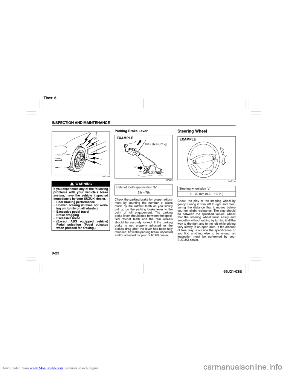
60G104
Parking Brake Lever
60A226
Check the parking brake for proper adjust-
ment by counting the number of clicks
made by the ratchet teeth as you slowly
pull up on the parking brake lever to the
point of full engagement. The parking
brake lever should stop between the speci-
fied ratchet teeth and the rear wheels
should be securely locked. If the parking
brake is not properly adjusted or the
brakes drag after the lever has been fully
released, have the parking brake inspected
and/or adjusted by your SUZUKI dealer.
Steering Wheel
54G110
Check the play of the steering wheel by
gently turning it from left to right and mea-
suring the distance that it moves before
you feel slight resistance. The play should
be between the specified values. Check
that the steering wheel turns easily and
smoothly without rattling by turning it all the
way to the right and to the left while driving
very slowly in an open area. If the amount
of free play is outside the specification or
you find anything else to be wrong, an
inspection must be performed by your
SUZUKI dealer.
WARNING
If you experience any of the following
problems with your vehicle’s brake
system, have the vehicle inspected
immediately by your SUZUKI dealer.
Poor braking performance
Uneven braking (Brakes not work-
ing uniformly on all wheels.)
Excessive pedal travel
Brake dragging
Excessive noise
(Except ABS equipped vehicle)
Pedal pulsation (Pedal pulsates
when pressed for braking.)
Ratchet tooth specification “b”
5th – 7th
200 N (44 lbs, 20 kg)
“b”
EXAMPLE
Steering wheel play “c”
0 – 30 mm (0.0 – 1.2 in.)EXAMPLE
Tires: 6
Page 162 of 211

Downloaded from www.Manualslib.com manuals search engine 9-24 INSPECTION AND MAINTENANCE
66J21-03E
Power Steering (if equipped)
64J155
(1) UPPER
(2) LOWER
Check the steering box case, vane pump
and hose connections for leaks or damage.Power Steering FluidCheck the fluid level by looking at the res-
ervoir in the engine compartment when the
fluid is cold (about room temperature).
Check that the fluid level is between the (1)
and (2) lines. If the fluid level is near the (2)
line, fill it up to the (1) line with an auto-
matic transmission fluid equivalent to ATF
DEXRON
®-II (Esso JWS 2326) or
DEXRON®-III. Do not overfill.
Clutch Pedal
64J154
Check the clutch pedal for smooth opera-
tion and clutch fluid level from time to time.
If clutch dragging is felt with the pedal fully
depressed, have the clutch inspected by
your SUZUKI dealer. If the clutch fluid level
is near the “MIN” line, fill it up to the “MAX”
line with DOT3 brake fluid.
TiresFor safe operation of your vehicle, it is
important that the tires be the correct type
and size, in good condition, and properly
inflated. Be sure to follow the requirements
and recommendations in this section.Tire Sidewall LabelingUseful information about a tire is molded
into its sidewall. The example below shows
a typical passenger car tire.
Typical Passenger Car Tire Sidewall
67D027
A. Tire Manufacturer
The name of the tire manufacturer is
shown here.
B. Tire Name/Model
The tire name or model is shown
here.
(1)
(2)
AH B
G
E
FD
J I
C
EXAMPLE
Tires: 6
Page 170 of 211
Downloaded from www.Manualslib.com manuals search engine 9-32 INSPECTION AND MAINTENANCE
66J21-03E
GLOSSARY OF TIRE TERMINOL-
OGYAccessory Weight – the combined weight
(in excess of those standard items which
may be replaced) of automatic transmis-
sion, power steering, power brakes, power
windows, power seats, radio, and heater,
to the extent that these items are available
as factory-installed equipment (whether
installed or not).
Cold Tire Inflation Pressure – the pressure
in a tire that has been driven less than 1
mile or has been standing for three hours
or more.
Curb Weight – the weight of a motor vehi-
cle with standard equipment including the
maximum capacity of fuel, oil, and coolant,
and, if so equipped, air conditioning and
additional weight optional engine.
Intended Outboard Sidewall – (1) the side-
wall that contains a whitewall, bears white
lettering or bears manufacturer, brand,
and/or model name molding that is higher
or deeper than the same molding on the
other sidewall of the tire, or (2) the outward
facing sidewall of an asymmetrical tire that
has a particular side that must always face
outward when mounted on a vehicle.
Maximum Inflation Pressure – the maxi-
mum cold inflation pressure a tire is
designed to support in normal service.
Maximum Loaded Vehicle Weight – the
sum of curb weight, accessory weight,vehicle capacity weight (total load capac-
ity), and production options weight.
Normal Occupant Weight – 68 kilograms
times the number of occupants specified in
the second column of Table 1 (shown
below).
Occupant distribution – distribution of
occupants in a vehicle as specified in the
third column of Table 1 (shown below).
Production Options Weight – the combined
weight of those installed regular production
options weighing over 2.3 kilograms in
excess of those standard items which they
replace, not previously considered in curb
weight or accessory weight, including
heavy duty brakes, ride levelers, roof rack,
heavy duty battery, and special trim.
Recommended Inflation Pressure – the
cold tire inflation pressure recommended
by a manufacturer.
Rim – metal support for a tire or tire and
tube assembly upon which the tire beads
are seated.
Vehicle Capacity Weight – the rated cargo
and luggage load plus 68 kilograms (150
lbs) times the vehicle’s designated seating
capacity.
Vehicle Maximum Load on the Tire – the
load on an individual tire that is determined
by distributing to each axle its share of the
maximum loaded vehicle weight and divid-
ing by two.Vehicle Normal Load on the Tire – the load
on an individual tire that is determined by
distributing to each axle its share of the
curb weight, accessory weight, and normal
occupant weight (distributed in accordance
with Table 1 shown below) and dividing by
2.
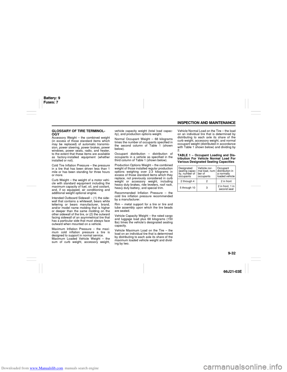
TABLE 1 – Occupant Loading and Dis-
tribution For Vehicle Normal Load For
Various Designated Seating Capacities
Designated
seating capac-
ity, number of
occupantsVehicle nor-
mal load, num-
ber of
occupantsOccupant
distribution in
a normally
loaded vehicle
2 through 4 2 2 in front
5 through 10 32 in front, 1 in
second seat
Battery: 9
Fuses: 7