cooling SUZUKI GRAND VITARA 2007 3.G Owners Manual
[x] Cancel search | Manufacturer: SUZUKI, Model Year: 2007, Model line: GRAND VITARA, Model: SUZUKI GRAND VITARA 2007 3.GPages: 211, PDF Size: 3.21 MB
Page 7 of 211
Downloaded from www.Manualslib.com manuals search engine 66J21-03E
LOCATION OF WARNING
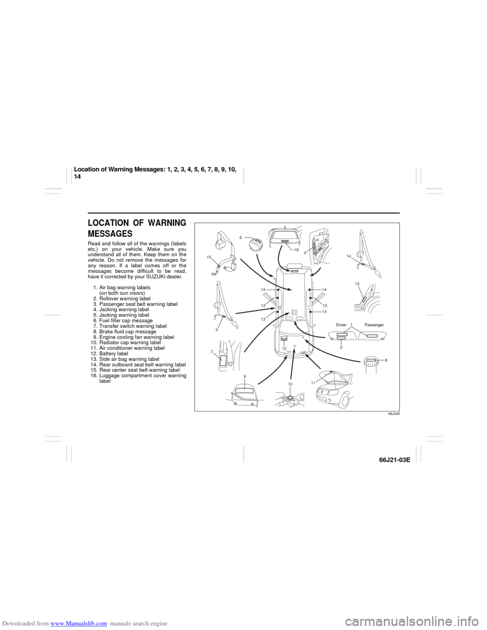
MESSAGESRead and follow all of the warnings (labels
etc.) on your vehicle. Make sure you
understand all of them. Keep them on the
vehicle. Do not remove the messages for
any reason. If a label comes off or the
messages become difficult to be read,
have it corrected by your SUZUKI dealer.
1. Air bag warning labels
(on both sun visors)
2. Rollover warning label
3. Passenger seat belt warning label
4. Jacking warning label
5. Jacking warning label
6. Fuel filler cap message
7. Transfer switch warning label
8. Brake fluid cap message
9. Engine cooling fan warning label
10. Radiator cap warning label
11. Air conditioner warning label
12. Battery label
13. Side air bag warning label
14. Rear outboard seat belt warning label
15. Rear center seat belt warning label
16. Luggage compartment cover warning
label
66J226
1
2
3
6
8 12
13 4 16
14
15
14
7
9
11
10
1413
13 1313
Driver Passenger
Location of Warning Messages: 1, 2, 3, 4, 5, 6, 7, 8, 9, 10,
14
Page 90 of 211
Downloaded from www.Manualslib.com manuals search engine 4-28 INSTRUMENT PANEL
66J21-03E
When you turn the air conditioning switch
off, the climate control system cannot
lower the inside temperature below outside
temperature.
To turn the climate control system off, turn
the blower speed selector (2) to the “OFF”
position.
NOTE:
To find your comfortable zone, start with
the 25°C (75°F) setting.
If you turn the temperature selector (1)
to the highest or lowest limit, the climate
control system will operate at the maxi-
mum cooling or heating and the blower
will run at full speed.
To avoid blowing cold air in cold weather
or hot air in hot weather, the system will
delay turning on the blower until warmed
or chilled air is available.
If your vehicle has been left in the sun
with the windows closed, it will cool
faster if you open the windows briefly.
Even under the automatic operation, you
can set some of the blower speed selec-
tor/air intake selector (2) and air flow
selector (3) into manual mode. Then the
manually selected function is maintained
preferentially, and the other functions
remain under automatic operation.
To return the air intake selector (2) to
automatic operation when both the
blower speed selector (2) and the air
flow selector (3) are in the “AUTO” posi-
tion, turn either the selector (2) or (3) toa position other than “AUTO”, then turn
to the “AUTO” position again.
64J080
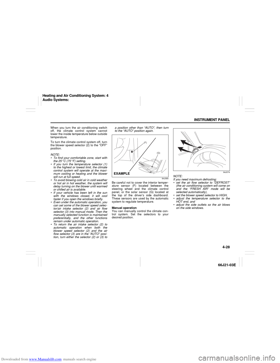
Be careful not to cover the interior temper-
ature sensor (F) located between the
steering wheel and the climate control
panel, or the solar sensor (G) located at
the top of the driver’s side dashboard.
These sensors are used by the automatic
system to regulate temperature.
Manual operation
You can manually control the climate con-
trol system. Set the selectors to your
desired position.
64J074
NOTE:
If you need maximum defrosting:
set the air flow selector to “DEFROST”
(the air conditioning system will come on
and the “FRESH AIR” mode will be
selected automatically),
set the blower speed selector to HIGH,
adjust the temperature selector to the
HOT end, and
adjust the side outlets so the air blows
on the side windows.
(F)
(G)
EXAMPLE
Heating and Air Conditioning System: 4
Audio Systems:
Page 141 of 211
Downloaded from www.Manualslib.com manuals search engine 9-3 INSPECTION AND MAINTENANCE
66J21-03E
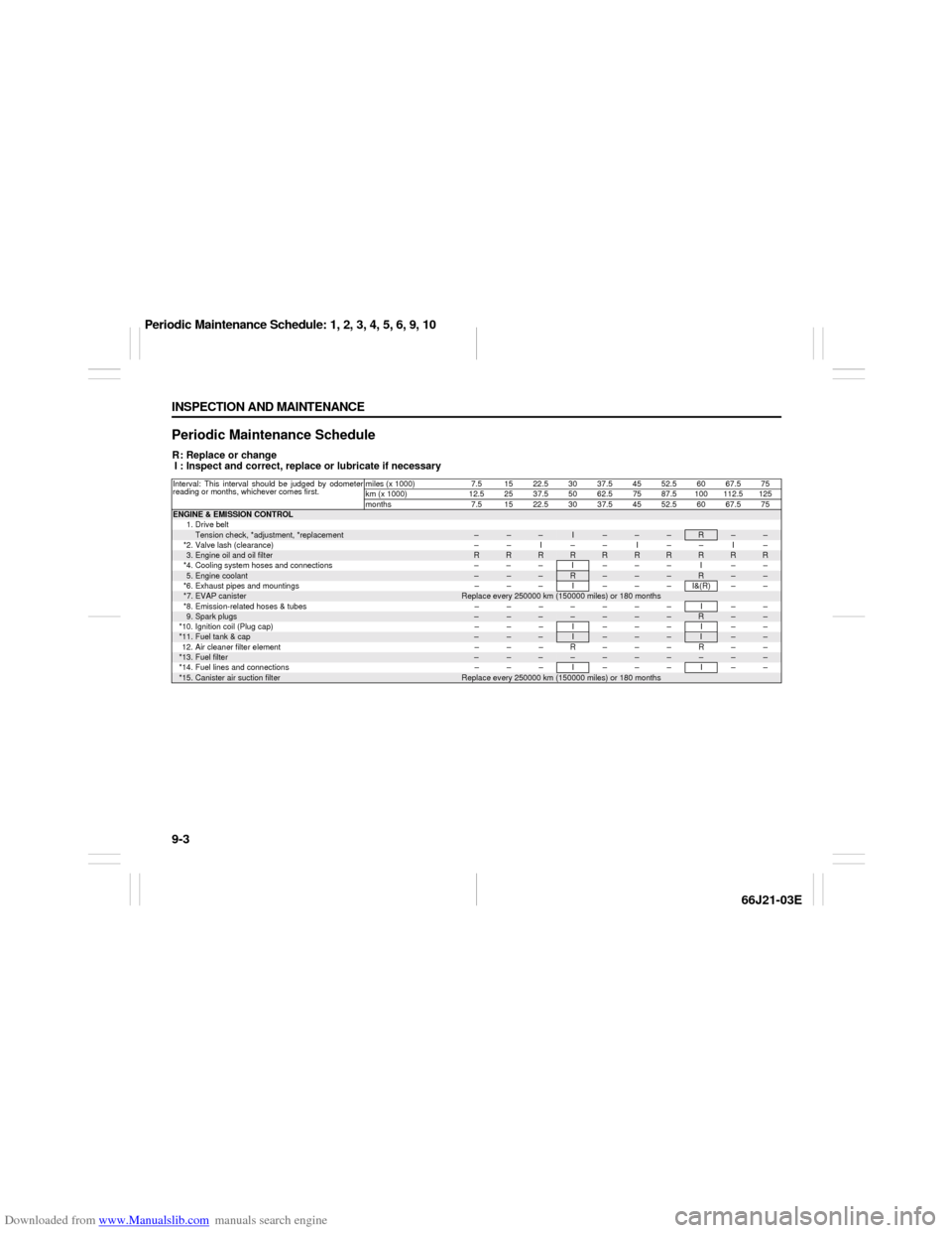
Periodic Maintenance ScheduleR: Replace or change
I : Inspect and correct, replace or lubricate if necessaryInterval: This interval should be judged by odometer
reading or months, whichever comes first.miles (x 1000) 7.5 15 22.5 30 37.5 45 52.5 60 67.5 75
km (x 1000) 12.52537.55062.57587.5100112.5125
months 7.5 1522.53037.54552.56067.575ENGINE & EMISSION CONTROL
1. Drive belt
Tension check, *adjustment, *replacement
–
–
–
I
–
–
–
R
–
–
*2. Valve lash (clearance) – – I – – I – – I –
3.Engine oil and oil filter
R
R
R
R
R
R
R
R
R
R
*4. Cooling system hoses and connections – – – I – – – I – –
5.Engine coolant
–
–
–
R
–
–
–
R
–
–
*6. Exhaust pipes and mountings – – – I – – – I&(R) – –
*7.
EVAP canister
Replace every 250000 km (150000 miles) or 180 months
*8. Emission-related hoses & tubes – – – – – – – I – –
9.Spark plugs
–
–
–
–
–
–
–
R
–
–
*10. Ignition coil (Plug cap) – – – I – – – I – –
*11.
Fuel tank & cap
–
–
–
I
–
–
–
I
–
–
12. Air cleaner filter element – – – R – – – R – –
*13.
Fuel filter
–
–
–
–
–
–
–
–
–
–
*14. Fuel lines and connections – – – I – – – I – –
*15.
Canister air suction filter
Replace every 250000 km (150000 miles) or 180 months
Periodic Maintenance Schedule: 1, 2, 3, 4, 5, 6, 9, 10
Page 142 of 211
Downloaded from www.Manualslib.com manuals search engine 9-4 INSPECTION AND MAINTENANCE
66J21-03E
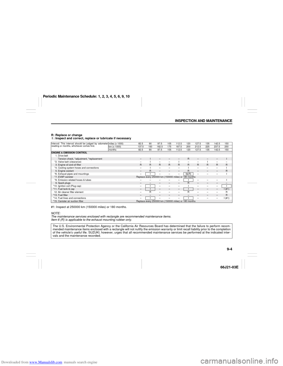
R: Replace or change
I : Inspect and correct, replace or lubricate if necessary
#1: Inspect at 250000 km (150000 miles) or 180 months.
NOTE:
The maintenance services enclosed with rectangle are recommended maintenance items.
Item 6 (R) is applicable to the exhaust mounting rubber only.Interval: This interval should be judged by odometer
reading or months, whichever comes first.miles (x 1000) 82.5 90 97.5 105 112.5 120 127.5 135 142.5 150
km (x 1000) 137.5 150 162.5 175 187.5 200 212.5 225 237.5 250
months 82.5 90 97.5 105 112.5 120 127.5 135 142.5 150ENGINE & EMISSION CONTROL
1. Drive beltTension check, *adjustment, *replacement
–
I
–
–
–
R
–
–
–
I
*2. Valve lash (clearance) – I – – I – – I – –3.Engine oil and oil filter
R
R
R
R
R
R
R
R
R
R
*4. Cooling system hoses and connections – I – – – I – – – I5.Engine coolant
–
R
–
–
–
R
–
–
–
R
*6. Exhaust pipes and mountings – I – – – I&(R) – – – I*7.
EVAP canister
Replace every 250000 km (150000 miles) or 180 months
*8. Emission-related hoses & tubes – – – – – I – – – I9.Spark plugs
–
–
–
–
–
R
–
–
–
–
*10. Ignition coil (Plug cap) – I – – – I – – – I*11.
Fuel tank & cap
–
I
–
–
–
I
–
–
–
I (#1)
12. Air cleaner filter element – R – – – R – – – R*13.
Fuel filter
–
–
–
–
–
–
–
–
–
R
*14. Fuel lines and connections – I – – – I – – – I (#1)*15.
Canister air suction filter
Replace every 250000 km (150000 miles) or 180 months
The U.S. Environmental Protection Agency or the California Air Resources Board has determined that the failure to perform recom-
mended maintenance items enclosed with a rectangle will not nullify the emission warranty or limit recall liability prior to the completion
of the vehicle’s useful life. SUZUKI, however, urges that all recommended maintenance services be performed at the indicated inter-
vals and the maintenance recorded.
Periodic Maintenance Schedule: 1, 2, 3, 4, 5, 6, 9, 10
Page 155 of 211
Downloaded from www.Manualslib.com manuals search engine 9-17 INSPECTION AND MAINTENANCE
66J21-03E
Engine Coolant
64J151
60A208
Selection of CoolantTo maintain optimum performance and
durability of your engine, use SUZUKI
Genuine Coolant or equivalent.
This type of coolant is best for your cooling
system as it:
Helps maintain proper engine tempera-
ture.
Gives proper protection against freezing
and boiling.
Gives proper protection against corro-
sion and rust.
Failure to use the proper coolant can dam-
age your cooling system. Your authorized
SUZUKI dealer can help you select the
proper coolant.
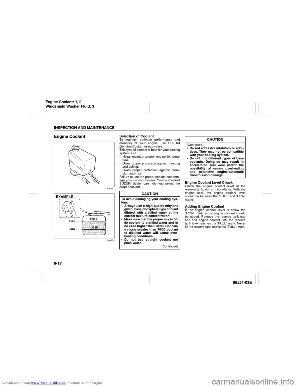
Engine Coolant Level CheckCheck the engine coolant level at the
reserve tank, not at the radiator. With the
engine cool, the engine coolant level
should be between the “FULL” and “LOW”
marks.Adding Engine CoolantIf the engine coolant level is below the
“LOW” mark, more engine coolant should
be added. Remove the reserve tank cap
and add engine coolant until the reserve
tank level reaches the “FULL” mark. Never
fill the reserve tank above the “FULL” mark.
EXAMPLE
FULL
LOW
CAUTION
To avoid damaging your cooling sys-
tem:
Always use a high quality ethylene
glycol base phosphate type coolant
diluted with distilled water at the
correct mixture concentration.
Make sure that the proper mix is 50/
50 coolant to distilled water and in
no case higher than 70/30. Concen-
trations greater than 70/30 coolant
to distilled water will cause over-
heating conditions.
Do not use straight coolant nor
plain water.
(Continued)
CAUTION
(Continued)
Do not add extra inhibitors or addi-
tives. They may not be compatible
with your cooling system.
Do not mix different types of base
coolants. Doing so may result in
accelerated seal wear and/or the
possibility of severe overheating
and extensive engine/automatic
transmission damage.
Engine Coolant: 1, 2
Windshield Washer Fluid: 3
Page 157 of 211
Downloaded from www.Manualslib.com manuals search engine 9-19 INSPECTION AND MAINTENANCE
66J21-03E
64J191
3) Loosen the drain plug attached to the
lower part of the radiator and drain the
engine coolant into a suitable container.
4) Reinstall the reservoir and fill it with
engine coolant to the “FULL” line.
5) Tighten the drain plug on the radiator,
fill the radiator with engine coolant and
install the radiator cap.
6) After filling, let the engine idle for about
2 – 3 minutes to get rid of air in the
cooling system. Then, stop the engine.
7) Check the engine coolant level in the
radiator again. If the level has gone
down, add more engine coolant.
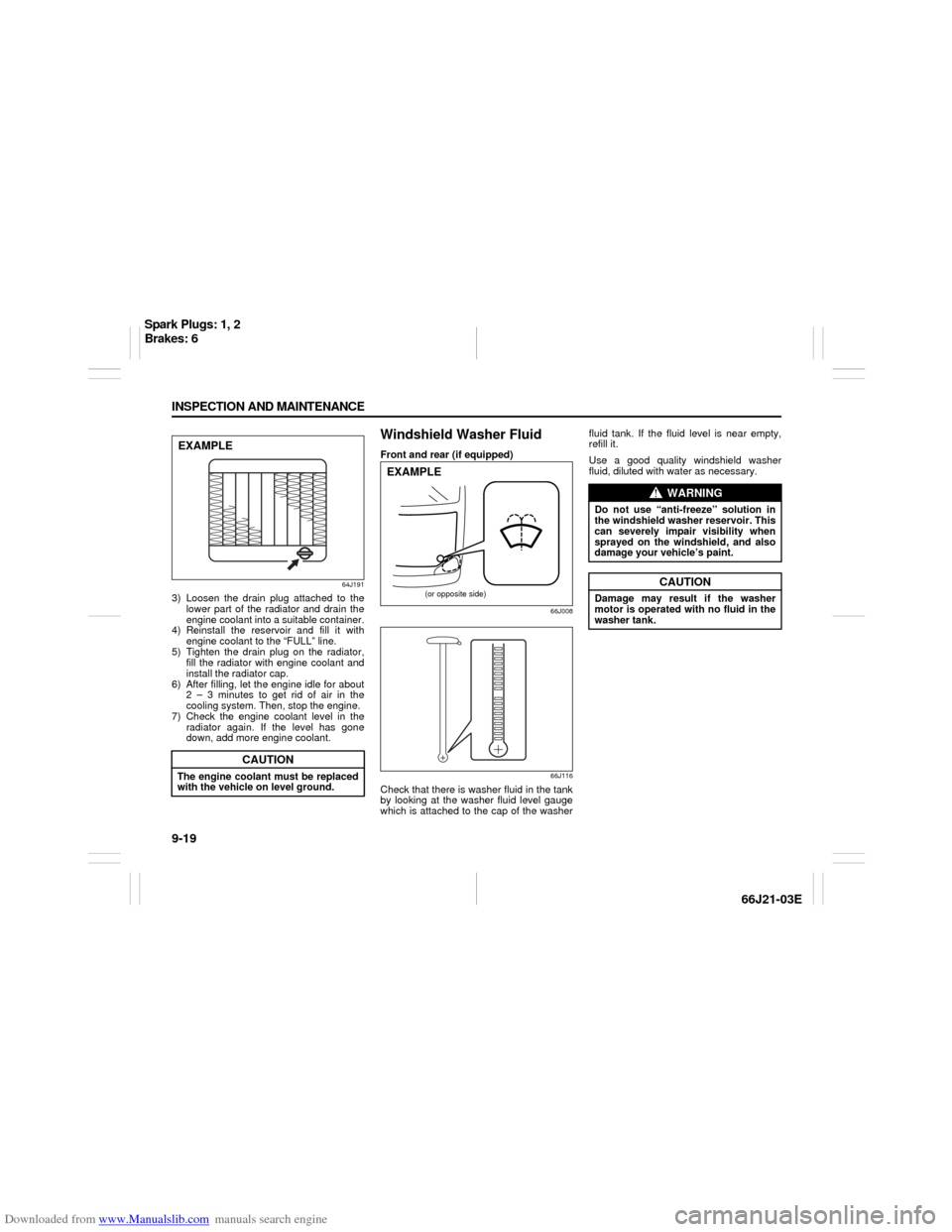
Windshield Washer FluidFront and rear (if equipped)
66J008
66J116
Check that there is washer fluid in the tank
by looking at the washer fluid level gauge
which is attached to the cap of the washerfluid tank. If the fluid level is near empty,
refill it.
Use a good quality windshield washer
fluid, diluted with water as necessary.
CAUTION
The engine coolant must be replaced
with the vehicle on level ground.EXAMPLE
(or opposite side)
EXAMPLE
WARNING
Do not use “anti-freeze” solution in
the windshield washer reservoir. This
can severely impair visibility when
sprayed on the windshield, and also
damage your vehicle’s paint.
CAUTION
Damage may result if the washer
motor is operated with no fluid in the
washer tank.
Spark Plugs: 1, 2
Brakes: 6