ECU SUZUKI GRAND VITARA 2008 3.G Inspection And Maintenance Manual
[x] Cancel search | Manufacturer: SUZUKI, Model Year: 2008, Model line: GRAND VITARA, Model: SUZUKI GRAND VITARA 2008 3.GPages: 48, PDF Size: 1.33 MB
Page 23 of 48

Downloaded from www.Manualslib.com manuals search engine NOTE: Do not check the fluid level if you have just driven the vehicle for a long time at high
speed, if you have driven in city traffic in hot weather, or if the vehicle has been pull
ing a trailer. Wait until the fluid cools down
(about
30 minutes), or the fluid level indica
tion will not be correct.
3} Park your vehicle on level ground. 4} Apply the parking brake and then start
the engine in "P" (Park). Let it idle for two minutes and keep it running during
the fluid level check. . 5} With your foot on the brake pedal, move the gearshift lever through each range,
pausing for about three seconds in each range. Then move it back to the "P" (Park) position.
A. WARNING
Be sure to depress the brake pedal
when moving the gearshift lever, or the vehicle can move suddenly.
EXAMPLE or
60A205
6} The handle of the AfT fluid dipstick is colored red for easy identification.
Remove the dipstick, clean it and push it back in until the cap seats. Then pull out the dipstick. 7} Check both sides of the dipstick, and read the lowest level. The fluid level should be between the two marks in the "HOT' range on the dipstick.
INSPECTION AND MAINTENANCE
(3)
I?
~ (1)
(2) Co
(1) FULL HOT (2) LOW HOT (3) The lowest point = Fluid level
64J188
8} Add just enough specified fluid through the dipstick hole to fill the transmission to the proper level.
CAUTION
After checking or adding oil, be sure to insert the dipstick securely.
Changing Oil Since special procedures, materials, and tools are required to change the automatic
transmission oil, it is recommended that you trust this job to your authorized . SUZUKI dealer.
7-22
Page 26 of 48

Downloaded from www.Manualslib.com manuals search engine INSPECTION AND MAINTENANCE
Parking Brake
EXAMPLE
Ratchet tooth specification "b": 5th -7th Lever pull force (1): 200 N (20 kg, 44 Ibs)
54G109
Check the parking brake for proper adjust
ment by counting the number of clicks made by the ratchet teeth as you slowly pull up on the parking brake lever to the
point of full engagement. The parking brake lever should stop between the speci
fied ratchet teeth and the rear wheels
should be securely locked. If the parking brake is not properly adjusted or the
brakes drag after the lever has been fully released, have the parking brake inspected
and/or adjusted by your SUZUKI dealer.
7-25
Steering
EXAMPLE
Steering wheel play "c": 0-30 mm (0.0 -1.2 in.)
\! "c"
{)
7BKOBO
Check the play of the steering wheel by gently turning it from left to right and mea
suring the distance that it moves before
you feel slight resistance. The play should be between the specified values.
Check that the steering wheel turns easily and smoothly without rattling by turning it all the way to the right and to the left while driving very slowly in an open area. If the
amount of free play is outside the specifi
cation or you find anything else to be wrong, an inspection must be performed by your SUZUKI dealer.
Power Steering (if equipped)
(1) UPPER (2) LOWER
(1)
(2)
64J155
Check the steering box case, vane pump and hose connections for leaks or damage.
Power Steering Fluid Check the fluid level by looking at the reservoir in the engine compartment when the fluid is cold (about room temperature).
Check that the fluid
level is between the (1) and (2) lines. If the fluid level is near the (2) line, fill it up to the (1) line with an auto
matic transmission fluid eauivalent to DEXRON®-II, DEXRON@-IIE or DEXRON®-III. Do not overfill.
Page 30 of 48

Downloaded from www.Manualslib.com manuals search engine INSPECTION AND MAINTENANCE
EXAMPLE (traditional type)
~"'-"""'-UPPER
LOWER
54G118
For maintenance-free battery (cap-less type), you need not add water. For tradi
tional type battery, which has water filler caps, the level of the battery solution must
be kept between the "UPPER" and the "LOWER" level lines at all times. If the level is found to be below the "LOWER" level
line, add distilled water to the "UPPER"
level line. You should periodically check the
battery, battery terminals, and battery hold-down bracket for corrosion. Remove
corrosion using a stiff brush and ammonia
mixed with water, or baking soda mixed
with water. After removing corrosion, rinse
with
clean water.
If your vehicle is not going to be driven for
a month or longer, disconnect the cable from the negative terminal of the battery to help prevent discharge.
7-29
Replacement of the battery
EXAMPLE (3) (1)
(2)
To remove the battery: 1) Disconnect the negative cable (1). 2) Disconnect the positive cable (2). 3) Remove the retainer nuts (3) and
remove the retainer (4). 4) Remove the battery.
To install the battery: 1) Install the battery in the reverse order of removal. 2) Tighten the retainer nuts and battery cables securely.
NOTE:
When the battery is disconnected, some of the vehicle's function will be initialized and/ or deactivated.
These function are required to reset after the battery is reconnected.
A WARNING
Batteries contain toxic substances including sulfuric acid and lead. They could have potential negative consequences for the environment and
human health. Used battery must be disposed or recycled according to
the local law and must not be discarded with ordinary household waste. Make sure not to tip over the
battery when you remove it from the vehicle. Otherwise, sulfuric acid could run out and you might get
injury.
Page 37 of 48

Downloaded from www.Manualslib.com manuals search engine Center Interior Light (if equipped)
64J159
Pull down the lens by using a plane screw
driver covered with a soft cloth as shown. To install it, simply push it back in.
The bulb can be removed by simply pulling it out. When replacing the bulb, make sure
that the contact springs are holding the bulb securely.
Rear Interior Light (if equipped)
64J160
Pull down the lens by using a plane screw
driver covered with a soft cloth as shown. To install it, simply push it back in. .
The
bulb can be removed by simply pulling it out.
INSPECTION AND MAINTENANCE
Spot Light (if equipped) . Pull down the lens by using a plane screw
driver covered with a soft cloth as shown.
Ceiling-mount type (if equipped)
79K061
Remove the bulb holder by turning it counterclockwise. Pull out the bulb.
7-36
Page 45 of 48
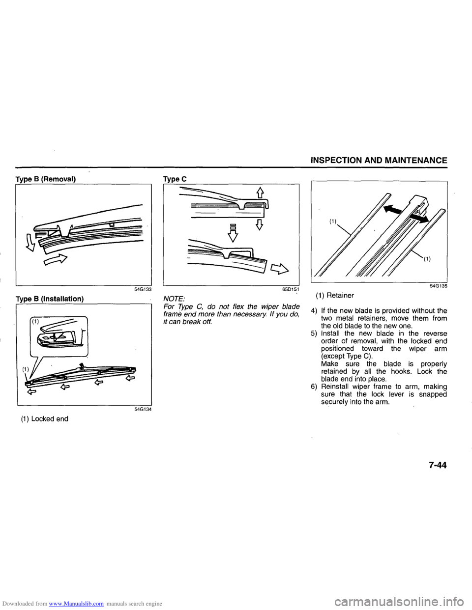
Downloaded from www.Manualslib.com manuals search engine Type B (Removal)
54G133
Type B (Installation)
54G134
(1) Locked end
TypeC
650151
NOTE:
For Type C, do not flex the wiper blade frame end more than necessary If you do, it can break off.
INSPECTION AND MAINTENANCE
(1) Retainer
4) If the new blade is provided without the
two metal retainers, move them from
the old blade to the new one. 5) Install the new blade in the reverse
order of removal, with the locked end
positioned toward the wiper arm
(except
Type C). Make sure the blade is properly
retained by all the hooks. Lock the
blade end into place.
6) Reinstall wiper frame to arm, making
sure that the lock lever is snapped
securely into the arm.
7-44