transmission SUZUKI GRAND VITARA 2008 3.G Owners Manual
[x] Cancel search | Manufacturer: SUZUKI, Model Year: 2008, Model line: GRAND VITARA, Model: SUZUKI GRAND VITARA 2008 3.GPages: 290, PDF Size: 4.99 MB
Page 1 of 290

Part No. 99011-66J22-03E
July, 2007
OWNER’S MANUAL
99011-66J22-03E GRAND VITARA
Printed in Japan
See page 1-1
12.5 mm
Keep With Vehicle At All Times.
Contains Important Information
On Safety, Operation & Maintenance.
SERVICE STATION INFORMATION
Fuel recommendation: Brake and clutch fluid:
Engine oil recommendation: Automatic transmission fluid:
Tire cold pressure:
For further details, see “Engine Oil and Filter” in the
“INSPECTION AND MAINTENANCE” section.DOT3
See the “Tire Information Label” located on the
driver’s door lock pillar.
2008Engine oil with “Starburst” symbol
Made from 100% recycled paper,
except for cover.
ENGLISH
Suzuki Red: PANTONE 485
Suzuki Blue: PANTONE 294
SUZUKI ATF 3317 or Mobil ATF 3309
Page 4 of 290
66J22-03E
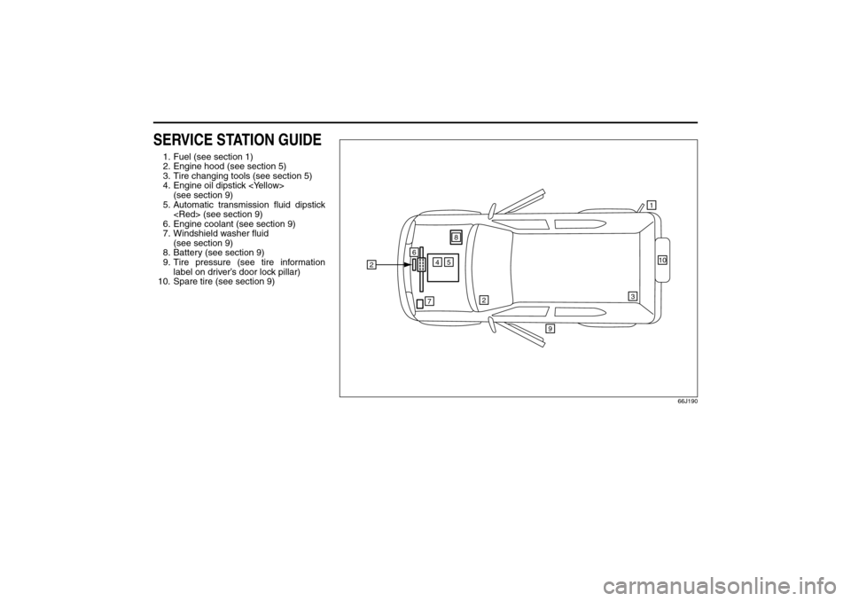
SERVICE STATION GUIDE1. Fuel (see section 1)
2. Engine hood (see section 5)
3. Tire changing tools (see section 5)
4. Engine oil dipstick
(see section 9)
5. Automatic transmission fluid dipstick
6. Engine coolant (see section 9)
7. Windshield washer fluid
(see section 9)
8. Battery (see section 9)
9. Tire pressure (see tire information
label on driver’s door lock pillar)
10. Spare tire (see section 9)
66J190
2
5
2
47
6
1
9
3
10
8
Page 62 of 290
3-1STEERING COLUMN CONTROLS
66J22-03E
65D611
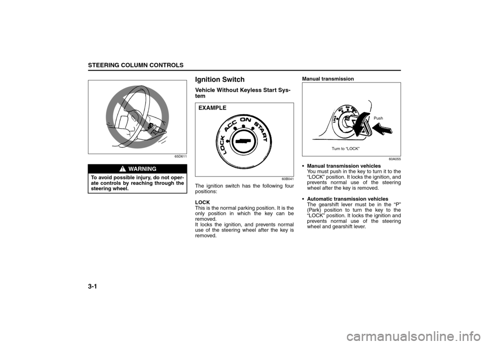
Ignition SwitchVehicle Without Keyless Start Sys-
tem
60B041
The ignition switch has the following four
positions:
LOCK
This is the normal parking position. It is the
only position in which the key can be
removed.
It locks the ignition, and prevents normal
use of the steering wheel after the key is
removed.Manual transmission
60A055
Manual transmission vehicles
You must push in the key to turn it to the
“LOCK” position. It locks the ignition, and
prevents normal use of the steering
wheel after the key is removed.
Automatic transmission vehicles
The gearshift lever must be in the “P”
(Park) position to turn the key to the
“LOCK” position. It locks the ignition and
prevents normal use of the steering
wheel and gearshift lever.
WARNING
To avoid possible injury, do not oper-
ate controls by reaching through the
steering wheel.
EXAMPLE
Push
Turn to “LOCK”
Ignition Switch: 8, 10
Page 65 of 290
3-4
STEERING COLUMN CONTROLS
66J22-03E
64J216
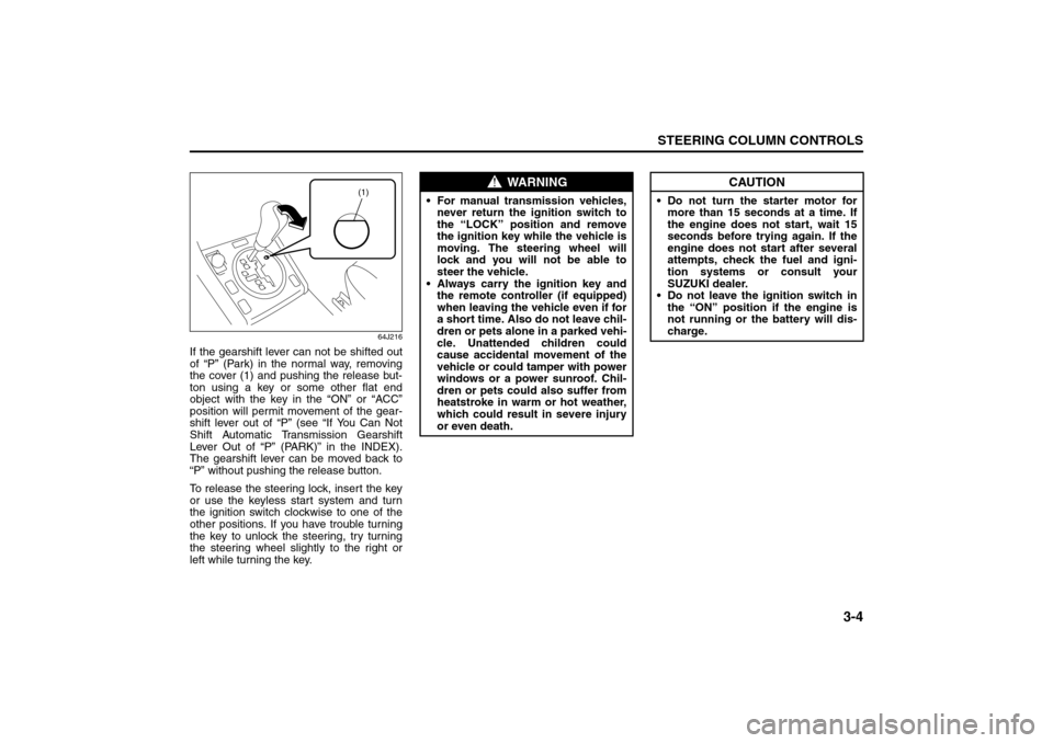
If the gearshift lever can not be shifted out
of “P” (Park) in the normal way, removing
the cover (1) and pushing the release but-
ton using a key or some other flat end
object with the key in the “ON” or “ACC”
position will permit movement of the gear-
shift lever out of “P” (see “If You Can Not
Shift Automatic Transmission Gearshift
Lever Out of “P” (PARK)” in the INDEX).
The gearshift lever can be moved back to
“P” without pushing the release button.
To release the steering lock, insert the key
or use the keyless start system and turn
the ignition switch clockwise to one of the
other positions. If you have trouble turning
the key to unlock the steering, try turning
the steering wheel slightly to the right or
left while turning the key.
(1)
WARNING
For manual transmission vehicles,
never return the ignition switch to
the “LOCK” position and remove
the ignition key while the vehicle is
moving. The steering wheel will
lock and you will not be able to
steer the vehicle.
Always carry the ignition key and
the remote controller (if equipped)
when leaving the vehicle even if for
a short time. Also do not leave chil-
dren or pets alone in a parked vehi-
cle. Unattended children could
cause accidental movement of the
vehicle or could tamper with power
windows or a power sunroof. Chil-
dren or pets could also suffer from
heatstroke in warm or hot weather,
which could result in severe injury
or even death.
CAUTION
Do not turn the starter motor for
more than 15 seconds at a time. If
the engine does not start, wait 15
seconds before trying again. If the
engine does not start after several
attempts, check the fuel and igni-
tion systems or consult your
SUZUKI dealer.
Do not leave the ignition switch in
the “ON” position if the engine is
not running or the battery will dis-
charge.
Ignition Switch: 8, 10
Page 86 of 290
4-11INSTRUMENT PANEL
66J22-03E
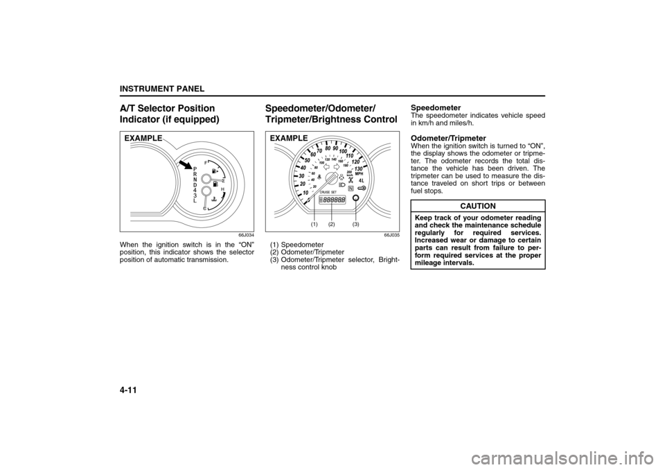
A/T Selector Position
Indicator (if equipped)
66J034
When the ignition switch is in the “ON”
position, this indicator shows the selector
position of automatic transmission.
Speedometer/Odometer/
Tripmeter/Brightness Control
66J035
(1) Speedometer
(2) Odometer/Tripmeter
(3) Odometer/Tripmeter selector, Bright-
ness control knob
SpeedometerThe speedometer indicates vehicle speed
in km/h and miles/h.Odometer/TripmeterWhen the ignition switch is turned to “ON”,
the display shows the odometer or tripme-
ter. The odometer records the total dis-
tance the vehicle has been driven. The
tripmeter can be used to measure the dis-
tance traveled on short trips or between
fuel stops.
EXAMPLE
(1)
(2)
(3)
EXAMPLE
CAUTION
Keep track of your odometer reading
and check the maintenance schedule
regularly for required services.
Increased wear or damage to certain
parts can result from failure to per-
form required services at the proper
mileage intervals.
A/T Selector Position Indicator: 8
Speedometer/Odometer/Trip meter/Meter Illumination
Control: 8
Page 132 of 290
5-1OTHER CONTROLS AND EQUIPMENT
66J22-03E
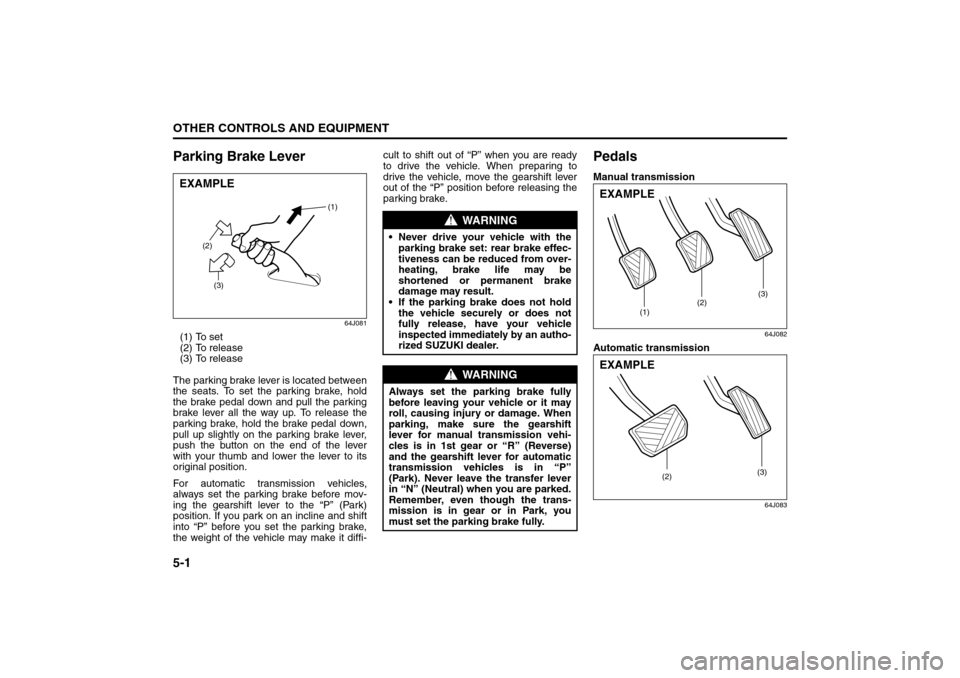
Parking Brake Lever
64J081
(1) To set
(2) To release
(3) To release
The parking brake lever is located between
the seats. To set the parking brake, hold
the brake pedal down and pull the parking
brake lever all the way up. To release the
parking brake, hold the brake pedal down,
pull up slightly on the parking brake lever,
push the button on the end of the lever
with your thumb and lower the lever to its
original position.
For automatic transmission vehicles,
always set the parking brake before mov-
ing the gearshift lever to the “P” (Park)
position. If you park on an incline and shift
into “P” before you set the parking brake,
the weight of the vehicle may make it diffi-cult to shift out of “P” when you are ready
to drive the vehicle. When preparing to
drive the vehicle, move the gearshift lever
out of the “P” position before releasing the
parking brake.
PedalsManual transmission
64J082
Automatic transmission
64J083
EXAMPLE
(2)
(3)(1)
WARNING
Never drive your vehicle with the
parking brake set: rear brake effec-
tiveness can be reduced from over-
heating, brake life may be
shortened or permanent brake
damage may result.
If the parking brake does not hold
the vehicle securely or does not
fully release, have your vehicle
inspected immediately by an autho-
rized SUZUKI dealer.
WARNING
Always set the parking brake fully
before leaving your vehicle or it may
roll, causing injury or damage. When
parking, make sure the gearshift
lever for manual transmission vehi-
cles is in 1st gear or “R” (Reverse)
and the gearshift lever for automatic
transmission vehicles is in “P”
(Park). Never leave the transfer lever
in “N” (Neutral) when you are parked.
Remember, even though the trans-
mission is in gear or in Park, you
must set the parking brake fully.
(1)(2)(3)
EXAMPLE
(2)(3)
EXAMPLE
Parking Brake Lever: 6
Pedals: 6
Page 133 of 290
5-2
OTHER CONTROLS AND EQUIPMENT
66J22-03E
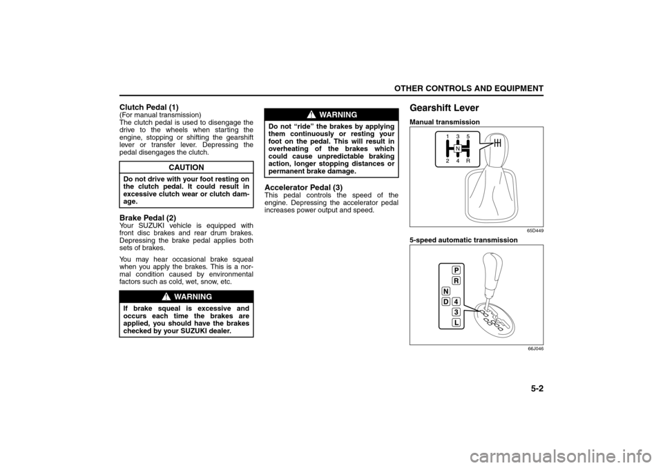
Clutch Pedal (1)(For manual transmission)
The clutch pedal is used to disengage the
drive to the wheels when starting the
engine, stopping or shifting the gearshift
lever or transfer lever. Depressing the
pedal disengages the clutch.Brake Pedal (2)Your SUZUKI vehicle is equipped with
front disc brakes and rear drum brakes.
Depressing the brake pedal applies both
sets of brakes.
You may hear occasional brake squeal
when you apply the brakes. This is a nor-
mal condition caused by environmental
factors such as cold, wet, snow, etc.
Accelerator Pedal (3)This pedal controls the speed of the
engine. Depressing the accelerator pedal
increases power output and speed.
Gearshift LeverManual transmission
65D449
5-speed automatic transmission
66J046
CAUTION
Do not drive with your foot resting on
the clutch pedal. It could result in
excessive clutch wear or clutch dam-
age.
WARNING
If brake squeal is excessive and
occurs each time the brakes are
applied, you should have the brakes
checked by your SUZUKI dealer.
WARNING
Do not “ride” the brakes by applying
them continuously or resting your
foot on the pedal. This will result in
overheating of the brakes which
could cause unpredictable braking
action, longer stopping distances or
permanent brake damage.
Pedals: 6
Gearshift Lever: 10
Page 134 of 290
5-3OTHER CONTROLS AND EQUIPMENT
66J22-03E
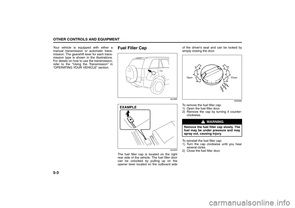
Your vehicle is equipped with either a
manual transmission or automatic trans-
mission. The gearshift lever for each trans-
mission type is shown in the illustrations.
For details on how to use the transmission,
refer to the “Using the Transmission” in
“OPERATING YOUR VEHICLE” section.
Fuel Filler Cap
64J085
64J253
The fuel filler cap is located on the right
rear side of the vehicle. The fuel filler door
can be unlocked by pulling up on the
opener lever located on the outboard sideof the driver’s seat and can be locked by
simply closing the door.
60G069
To remove the fuel filler cap:
1) Open the fuel filler door.
2) Remove the cap by turning it counter-
clockwise.
To reinstall the fuel filler cap:
1) Turn the cap clockwise until you hear
several clicks.
2) Close the fuel filler door.
EXAMPLE
WARNING
Remove the fuel filler cap slowly. The
fuel may be under pressure and may
spray out, causing injury.Open Close
Gearshift Lever: 10
Fuel Filler Cap: 5
Page 156 of 290
5-25OTHER CONTROLS AND EQUIPMENT
66J22-03E
HomeLink
® (if equipped)
66J092
HomeLink
® and the HomeLink
® house are
registered trademarks of Johnson
Controls, Inc.
The HomeLink
® Wireless Control System
provides a convenient way to replace up to
three hand-held radio-frequency (RF)
transmitters used to activate devices such
as gate operators, garage door openers,
entry door locks, security systems, even
home lighting. Additional HomeLink
® infor-
mation can be found on the Internet at
www.homelink.com
or by calling 1-800-
355-3515.
Before programming HomeLink
® to a
garage door opener or gate operator,
make sure that people and objects are out
of the way of the device to prevent poten-
tial harm or damage. When programming a
garage door opener, it is advised to park
outside of the garage. Do not use
HomeLink
® with any garage door opener
that lacks safety stop and reverse features
as required by U.S. federal safety stan-dards (this includes any garage door
opener model manufactured before April 1,
1982). A garage door that cannot detect an
object – signaling the door to stop and
reverse – does not meet current U.S. fed-
eral safety standards. For more informa-
tion, contact HomeLink
® at
www.homelink.com
or by calling 1-800-
355-3515.
Retain the original transmitter of the RF
device you are programming for use in
other vehicles as well as for future
HomeLink
® programming. It is also sug-
gested that upon the sale of the vehicle,
the programmed HomeLink
® buttons be
erased for security purposes. Refer to
“Programming HomeLink
®” (step 1) only)
or, for assistance, contact HomeLink
® at
www.homelink.com
or by calling 1-800-
355-3515.
Programming HomeLink
®
NOTE:
Some vehicles may require the ignition
switch to be turned to the second (or
“accessories”) position or the “on” position
for programming and/or operation of
HomeLink
®. It is also recommended that a
new battery be placed in the hand-held
transmitter of the device being pro-
grammed to HomeLink
® for quicker train-
ing and accurate transmission of the radio-
frequency signal. Do not repeat “Program-
ming HomeLink
®” – step 1) to train addi-
tional devices to a second or thirdHomeLink
® button. Begin with “Program-
ming HomeLink
®” – step 2).
66J050
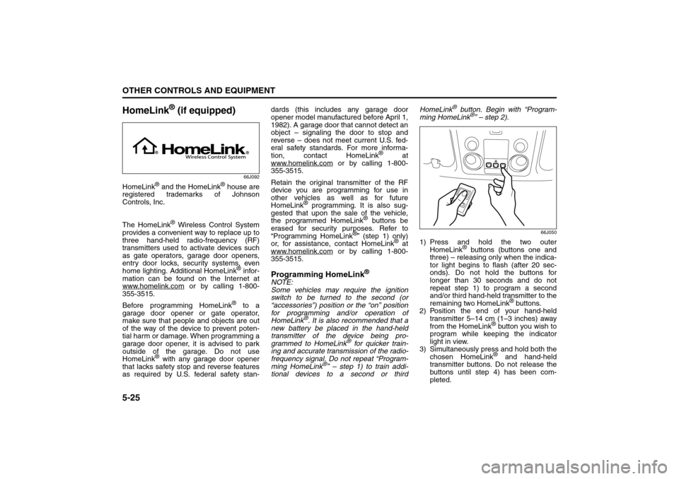
1) Press and hold the two outer
HomeLink
® buttons (buttons one and
three) – releasing only when the indica-
tor light begins to flash (after 20 sec-
onds). Do not hold the buttons for
longer than 30 seconds and do not
repeat step 1) to program a second
and/or third hand-held transmitter to the
remaining two HomeLink
® buttons.
2) Position the end of your hand-held
transmitter 5–14 cm (1–3 inches) away
from the HomeLink
® button you wish to
program while keeping the indicator
light in view.
3) Simultaneously press and hold both the
chosen HomeLink® and hand-held
transmitter buttons. Do not release the
buttons until step 4) has been com-
pleted.
HomeLink:
Page 158 of 290

5-27OTHER CONTROLS AND EQUIPMENT
66J22-03E
Gate Operator / Canadian Program-
mingCanadian radio-frequency laws require
transmitter signals to “time-out” (or quit)
after several seconds of transmission –
which may not be long enough for
HomeLink
® to pick up the signal during
programming. Similar to this Canadian law,
some U.S. gate operators are designed to
“time-out” in the same manner.
If you live in Canada or you are having dif-
ficulties programming a gate operator by
using the Programming procedures
(regardless of where you live), replace
“Programming HomeLink
®” step 3) with
the following:
NOTE:
If programming a garage door opener or
gate operator, it is advised to unplug the
device during the “cycling” process to pre-
vent possible overheating.
3) Continue to press and hold the
HomeLink
® button while you press and
release – every two seconds (“cycle”)
your hand-held transmitter until the fre-
quency signal has successfully been
accepted by HomeLink
®. (The indicator
light will flash slowly and then rapidly.)
Proceed with “Programming HomeLink
®”
step 4) to complete.
Using HomeLink
®
To operate, simply press and release the
programmed HomeLink
® button. Activation
will now occur for the trained device (i.e.
garage door opener, gate operator, secu-
rity system, entry door lock, home/office
lighting, etc.). For convenience, the hand-
held transmitter of the device may also be
used at any time. In the event that there
are still programming difficulties or ques-
tions, contact HomeLink
® at
www.homelink.com
or 1-800-355-3515.
Erasing HomeLink
® Buttons
To erase programming from the three but-
tons (individual buttons cannot be erased
but can be “reprogrammed” as outlined
below), follow the step noted:
Press and hold the two outer HomeLink
®
buttons until the indicator light begins to
flash-after 20 seconds. Release both but-
tons. Do not hold for longer that 30 sec-
onds. HomeLink
® is now in the train (or
learning) mode and can be programmed at
any time beginning with “Programming
HomeLink
®” – step 2).
Reprogramming a Single
HomeLink
® Button
To program a device to HomeLink
® using a
HomeLink
® button previously trained, fol-
low these steps:
1) Press and hold the desired HomeLink
®
button. DO NOT release the button.2) The indicator light will begin to flash
after 20 seconds. Without releasing the
HomeLink
® button, proceed with “Pro-
gramming HomeLink
®” – step 2).
For questions or comments, contact
HomeLink
® at www.homelink.com
or 1-
800-355-3515.