battery SUZUKI GRAND VITARA 2011 User Guide
[x] Cancel search | Manufacturer: SUZUKI, Model Year: 2011, Model line: GRAND VITARA, Model: SUZUKI GRAND VITARA 2011Pages: 337, PDF Size: 6.21 MB
Page 75 of 337
2-58
BEFORE DRIVING
79K21-03E
Anti-Lock Brake System (ABS)
Warning Light
65D529
When the ignition switch is turned to the
“ON” position, the light comes on briefly so
you can check that the light is working. If
the light stays on, or comes on when driv-
ing, there may be something wrong with
the ABS.
If the ABS light and the brake system
warning light stay on, or come on simulta-
neously when driving, then there may be
something wrong with both the rear brake
proportioning valve function and anti-lock
function of the ABS system.
If one of these happens, have the system
inspected by your SUZUKI dealer. If the
ABS becomes inoperative, the brake sys-
tem will function as an ordinary brake sys-
tem that has no ABS.
For details of the ABS, refer to “Anti-Lock
Brake system (ABS)” in the “OPERATING
YOUR VEHICLE” section.
SLIP Indicator Light
79K019
ESP
® is a registered trademark of Daimler
AG.
This light blinks 5 times per second when
one of the following systems is activated.
Stability control system
Traction control system
Hill descent control system (if equipped)
If this light blinks, drive carefully.
When the ignition switch is turned to the
“ON” position, the light comes on briefly so
you can check that the light is working. If
the light stays on, or comes on when driv-
ing and remains on, there may be some-
thing wrong with the ESP
® systems (other
than ABS). You should have the system
inspected by an authorized SUZUKI
dealer.
NOTE:
When you disconnect and re-connect the
battery, ESP
® system functions other than
ABS will be deactivated and the slip indica-
tor light will blink 1 time per second. Fordetails on how to reactivate the ESP
® sys-
tems, refer to “SLIP Indicator Light” in the
“OPERATING YOUR VEHICLE” section.
For details of the ESP
® systems, refer to
“Electronic Stability Program (ESP
®)” in
the “OPERATING YOUR VEHICLE” sec-
tion.
WARNING
The ESP
® systems cannot prevent
accidents. Always drive carefully.
Page 77 of 337
2-60
BEFORE DRIVING
79K21-03E
Hill descent control Indicator Light
79K050
When the ignition switch is turned to the
“ON” position, this light comes on briefly so
you can check that the light is working.
When you push the hill descent control
switch and the hill descent control operat-
ing conditions are fulfilled, the hill descent
control indicator comes on. If the hill
descent control indicator blinks, the hill
descent control will not be activated.
For details of the hill descent control sys-
tem, refer to “Hill descent control System”
in the “OPERATING YOUR VEHICLE” sec-
tion.
Oil Pressure Light
50G051
This light comes on when the ignition
switch is turned to the “ON” position, and
goes out when the engine is started. The
light will come on and remain on if there is
insufficient oil pressure. If the light comes
on when driving, pull off the road as soon
as you can and stop the engine. Check the
oil level and add oil if necessary. If there is
enough oil, the lubrication system should
be inspected by your SUZUKI dealer
before you drive the vehicle again.
Charging Light
50G052
This light comes on when the ignition
switch is turned to the “ON” position, and
goes out when the engine is started. The
light will come on and remain on if there is
something wrong with the battery charging
system. If the light comes on when the
engine is running, the charging system
should be inspected immediately by your
SUZUKI dealer.
CAUTION
If you operate the engine with this
light on, severe engine damage can
result.
Do not rely on the Oil Pressure
Light to indicate the need to add
oil. Be sure to periodically check
the engine oil level.
Page 84 of 337
2-67BEFORE DRIVING
79K21-03E
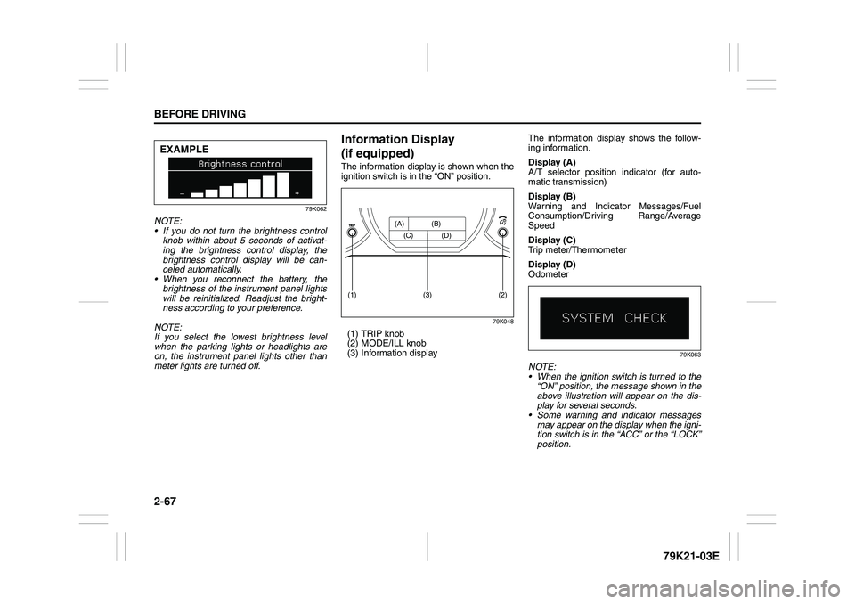
79K062
NOTE:
If you do not turn the brightness control
knob within about 5 seconds of activat-
ing the brightness control display, the
brightness control display will be can-
celed automatically.
When you reconnect the battery, the
brightness of the instrument panel lights
will be reinitialized. Readjust the bright-
ness according to your preference.
NOTE:
If you select the lowest brightness level
when the parking lights or headlights are
on, the instrument panel lights other than
meter lights are turned off.
Information Display
(if equipped)The information display is shown when the
ignition switch is in the “ON” position.
79K048
(1) TRIP knob
(2) MODE/ILL knob
(3) Information displayThe information display shows the follow-
ing information.
Display (A)
A/T selector position indicator (for auto-
matic transmission)
Display (B)
Warning and Indicator Messages/Fuel
Consumption/Driving Range/Average
Speed
Display (C)
Trip meter/Thermometer
Display (D)
Odometer
79K063
NOTE:
When the ignition switch is turned to the
“ON” position, the message shown in the
above illustration will appear on the dis-
play for several seconds.
Some warning and indicator messages
may appear on the display when the igni-
tion switch is in the “ACC” or the “LOCK”
position.
EXAMPLE
(2)
(1)
(3)
(A) (B)
(C) (D)
Page 86 of 337
2-69BEFORE DRIVING
79K21-03E
Instantaneous fuel consumption
If you selected instantaneous fuel con-
sumption the last time you drove the vehi-
cle, the display does not show the bar
graph when the ignition switch is turned to
the “ON” position. The display shows the
bar graph only when the vehicle is moving.
Average fuel consumption
If you selected average fuel consumption
the last time you drove the vehicle, the dis-
play shows the last value of average fuel
consumption from previous driving when
the ignition switch is turned to the “ON”
position. Unless you reset the value of
average fuel consumption, the display indi-
cates the value of average fuel consump-
tion which includes average fuel
consumption during previous driving.
NOTE:
When you reconnect the negative (–) ter-
minal to the battery, the value of average
fuel consumption will be shown after driv-
ing for a while.You can select when the value of average
fuel consumption is reset from among the
following three methods;
Reset after refuel: the value of average
fuel consumption will be reset automati-
cally by refueling.
Reset with trip A: the value of average
fuel consumption will be reset automati-
cally by resetting trip meter A.
Reset manually: the value of average
fuel consumption will be reset by push-
ing and holding the MODE/ILL knob (2)
when the display indicates the average
fuel consumption.
To change when the value of average fuel
consumption is reset, refer to “Setting
Mode” later in this section.
NOTE:
If you add only a small amount of fuel
when you select “Reset after refuel”, the
average fuel consumption value may not
be reset.Driving range
If you selected driving range the last time
you drove the vehicle, the display indicates
“---” for a few seconds and then indicates
the current driving range when the ignition
switch is turned to the “ON” position.
The driving range shown in the display is
the approximate distance you can drive
until the fuel gauge indicates “E”, based on
current driving conditions.
When the remaining fuel in fuel tank
reaches a low level, the display “---” will
appear.
If the low fuel warning light comes on, fill
the fuel tank immediately regardless of the
value of driving range shown in the display.
As the driving range after refueling is cal-
culated based on the most recent driving
condition, the value is different each time
you refuel.
NOTE:
If you refuel when the ignition switch is in
the “ON” position, the driving range may
not indicate the correct value.
When you reconnect the negative (–) ter-
minal to the battery, the value of driving
range will be shown after driving for a
while.
Page 87 of 337
2-70
BEFORE DRIVING
79K21-03E
Average speed
If you selected average speed the last time
you drove the vehicle, the display indicates
the last value of average speed from previ-
ous driving when the ignition switch is
turned to the “ON” position. Unless you
reset the value of average speed, the dis-
play indicates the value of average speed
which includes average speed during pre-
vious driving.
To reset the value of average speed, push
and hold the MODE/ILL knob (2) for about
2 seconds when the display indicates an
average speed. The display shows “---”
and then indicates a new average speed
after driving for a short time.
NOTE:
When you reconnect the negative (–) ter-
minal to the battery, the value of average
speed will be shown after driving for a
while.
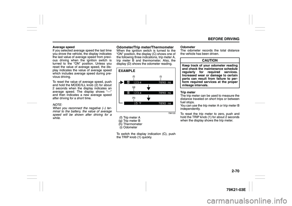
Odometer/Trip meter/ThermometerWhen the ignition switch is turned to the
“ON” position, the display (C) shows one of
the following three indications, trip meter A,
trip meter B and thermometer. Also, the
display (D) shows the odometer reading.
79K122
(f) Trip meter A
(g) Trip meter B
(h) Thermometer
(i) Odometer
To switch the display indication (C), push
the TRIP knob (1) quickly.Odometer
The odometer records the total distance
the vehicle has been driven.
Trip meter
The trip meter can be used to measure the
distance traveled on short trips or between
fuel stops.
You can use the trip meter A or trip meter B
independently.
To reset the trip meter to zero, push and
hold the TRIP knob (1) for about 2 seconds
when the display shows the trip meter.EXAMPLE
(f) (i)
(g)
(h)
CAUTION
Keep track of your odometer reading
and check the maintenance schedule
regularly for required services.
Increased wear or damage to certain
parts can result from failure to per-
form required services at the proper
mileage intervals.
Page 103 of 337
3-2
OPERATING YOUR VEHICLE
79K21-03E
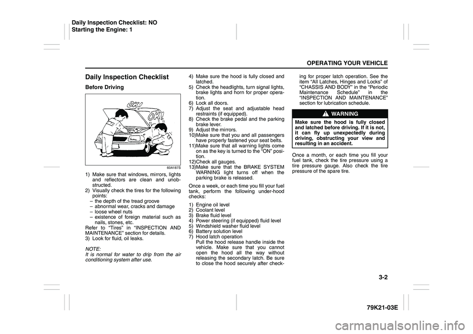
Daily Inspection ChecklistBefore Driving
60A187S
1) Make sure that windows, mirrors, lights
and reflectors are clean and unob-
structed.
2) Visually check the tires for the following
points:
– the depth of the tread groove
– abnormal wear, cracks and damage
– loose wheel nuts
– existence of foreign material such as
nails, stones, etc.
Refer to “Tires” in “INSPECTION AND
MAINTENANCE” section for details.
3) Look for fluid, oil leaks.
NOTE:
It is normal for water to drip from the air
conditioning system after use.4) Make sure the hood is fully closed and
latched.
5) Check the headlights, turn signal lights,
brake lights and horn for proper opera-
tion.
6) Lock all doors.
7) Adjust the seat and adjustable head
restraints (if equipped).
8) Check the brake pedal and the parking
brake lever.
9) Adjust the mirrors.
10)Make sure that you and all passengers
have properly fastened your seat belts.
11)Make sure that all warning lights come
on as the key is turned to the “ON” posi-
tion.
12)Check all gauges.
13)Make sure that the BRAKE SYSTEM
WARNING light turns off when the
parking brake is released.
Once a week, or each time you fill your fuel
tank, perform the following under-hood
checks:
1) Engine oil level
2) Coolant level
3) Brake fluid level
4) Power steering (if equipped) fluid level
5) Windshield washer fluid level
6) Battery solution level
7) Hood latch operation
Pull the hood release handle inside the
vehicle. Make sure that you cannot
open the hood all the way without
releasing the secondary latch. Be sure
to close the hood securely after check-ing for proper latch operation. See the
item “All Latches, Hinges and Locks” of
“CHASSIS AND BODY” in the “Periodic
Maintenance Schedule” in the
“INSPECTION AND MAINTENANCE”
section for lubrication schedule.
Once a month, or each time you fill your
fuel tank, check the tire pressure using a
tire pressure gauge. Also check the tire
pressure of the spare tire.
WARNING
Make sure the hood is fully closed
and latched before driving. If it is not,
it can fly up unexpectedly during
driving, obstructing your view and
resulting in an accident.
Daily Inspection Checklist: NO
Starting the Engine: 1
Page 105 of 337
3-4
OPERATING YOUR VEHICLE
79K21-03E
ACC
Accessories such as the radio can oper-
ate, but the engine is off.
ON
This is the normal operating position. All
electrical systems are on.
START
This is the position for starting the engine
using the starter motor. The key should be
released from this position as soon as the
engine starts.
Ignition key reminder
A buzzer sounds intermittently to remind
you to remove the ignition key if it is in the
ignition switch when the driver’s door is
opened.
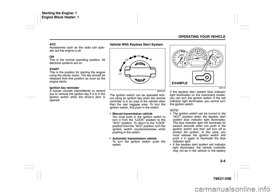
Vehicle With Keyless Start System
56KN076
The ignition switch can be operated with-
out using an ignition key when the remote
controller is in an area of the vehicle other
than the rear luggage area. To turn the
ignition switch, first push in the switch.
Manual transmission vehicle
You must push in the ignition switch to
turn it from the “LOCK” position to the
“ACC” position. To return to the “LOCK”
position from the “ACC” position, turn the
ignition switch counterclockwise while
pushing in the switch.
Automatic transmission vehicle
To turn the ignition switch, push the
switch.
79K116
If the keyless start system blue indicator
light illuminates on the instrument cluster,
you can turn the ignition switch. If the red
indicator light illuminates, you cannot turn
the ignition switch.
NOTE:
The ignition switch can be turned to the
“ACC” position when the keyless start
system blue indicator light illuminates.
The blue indicator light will illuminate for
several seconds when you push in the
ignition switch and then will turn off to
protect the system. In this case, you
must release the ignition switch and
push it in again to illuminate the blue
indicator light.
If the keyless start system red indicator
light illuminates, the remote controller
may not be in the vehicle or the battery
(1)(2)(3)
(4)
EXAMPLE
Starting the Engine: 1
Engine Block Heater: 1
Page 106 of 337
3-5OPERATING YOUR VEHICLE
79K21-03E
of the remote controller may be unreli-
able.
NOTE:
If the battery of the remote controller
runs down or there are strong radio
waves or noise, the operating range may
be narrower or the remote controller may
be inoperative.
If the remote controller is too close to the
door, it may not operate.
The ignition switch may not turn when
the remote controller is on the instru-
ment panel, in the glove box, in a stor-
age compartment, in the sun visor or on
the floor.You can also turn the ignition switch by
inserting the ignition key into the slot.
If you leave any of the doors open with the
ignition switch in the “ACC” position for a
while (and no key inserted), the engine
may not start when you turn the ignition
switch to “START”. If the engine does not
start, close all doors completely or turn the
ignition switch back to the “LOCK” position,
then start the engine.The ignition switch has the following four
positions:
LOCK (1)
This is the normal parking position. It is the
only position in which the key can be
removed. It locks the ignition, and prevents
normal use of the steering wheel.
For vehicles with an automatic transmis-
sion, the gearshift lever must be in the “P”
(Park) position to turn the key to the
“LOCK” position.
To release the steering lock, turn the igni-
tion switch clockwise to one of the other
positions. If you have trouble turning the
ignition switch to unlock the steering, try
turning the steering wheel slightly to the
right or left while turning the switch.
Manual transmission vehicle
You must push in the ignition switch to
turn it from the “LOCK” position to the
“ACC” position. To return to the “LOCK”
position from the “ACC” position, turn the
ignition switch counterclockwise while
pushing in the switch.
Automatic transmission vehicle
To turn the ignition switch, push the
switch.
ACC (2)
Accessories such as the radio can oper-
ate, but the engine is off.
CAUTION
The remote controller is a sensitive
electronic instrument. To avoid dam-
aging the remote controller:
Do not expose it to impacts, mois-
ture or high temperature such as by
leaving it on the dashboard under
direct sunlight.
Keep the remote controller away
from magnetic objects such as a
television.
Engine Block Heater: 1
Using the Transmission: 10
Page 108 of 337
3-7OPERATING YOUR VEHICLE
79K21-03E
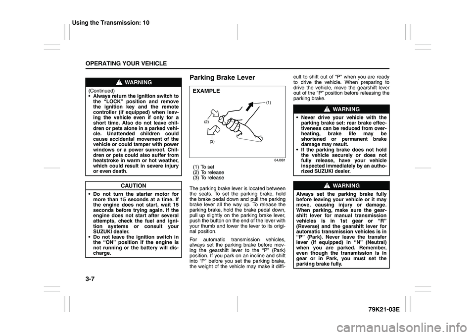
Parking Brake Lever
64J081
(1) To set
(2) To release
(3) To release
The parking brake lever is located between
the seats. To set the parking brake, hold
the brake pedal down and pull the parking
brake lever all the way up. To release the
parking brake, hold the brake pedal down,
pull up slightly on the parking brake lever,
push the button on the end of the lever with
your thumb and lower the lever to its origi-
nal position.
For automatic transmission vehicles,
always set the parking brake before mov-
ing the gearshift lever to the “P” (Park)
position. If you park on an incline and shift
into “P” before you set the parking brake,
the weight of the vehicle may make it diffi-cult to shift out of “P” when you are ready
to drive the vehicle. When preparing to
drive the vehicle, move the gearshift lever
out of the “P” position before releasing the
parking brake.
WARNING
(Continued)
Always return the ignition switch to
the “LOCK” position and remove
the ignition key and the remote
controller (if equipped) when leav-
ing the vehicle even if only for a
short time. Also do not leave chil-
dren or pets alone in a parked vehi-
cle. Unattended children could
cause accidental movement of the
vehicle or could tamper with power
windows or a power sunroof. Chil-
dren or pets could also suffer from
heatstroke in warm or hot weather,
which could result in severe injury
or even death.
CAUTION
Do not turn the starter motor for
more than 15 seconds at a time. If
the engine does not start, wait 15
seconds before trying again. If the
engine does not start after several
attempts, check the fuel and igni-
tion systems or consult your
SUZUKI dealer.
Do not leave the ignition switch in
the “ON” position if the engine is
not running or the battery will dis-
charge.
EXAMPLE
(2)
(3)(1)
WARNING
Never drive your vehicle with the
parking brake set: rear brake effec-
tiveness can be reduced from over-
heating, brake life may be
shortened or permanent brake
damage may result.
If the parking brake does not hold
the vehicle securely or does not
fully release, have your vehicle
inspected immediately by an autho-
rized SUZUKI dealer.
WARNING
Always set the parking brake fully
before leaving your vehicle or it may
move, causing injury or damage.
When parking, make sure the gear-
shift lever for manual transmission
vehicles is in 1st gear or “R”
(Reverse) and the gearshift lever for
automatic transmission vehicles is in
“P” (Park). Never leave the transfer
lever (if equipped) in “N” (Neutral)
when you are parked. Remember,
even though the transmission is in
gear or in Park, you must set the
parking brake fully.
Using the Transmission: 10
Page 116 of 337
3-15OPERATING YOUR VEHICLE
79K21-03E
If You Cannot Shift Automatic
Transmission Gearshift Lever Out
of “P” (PARK)
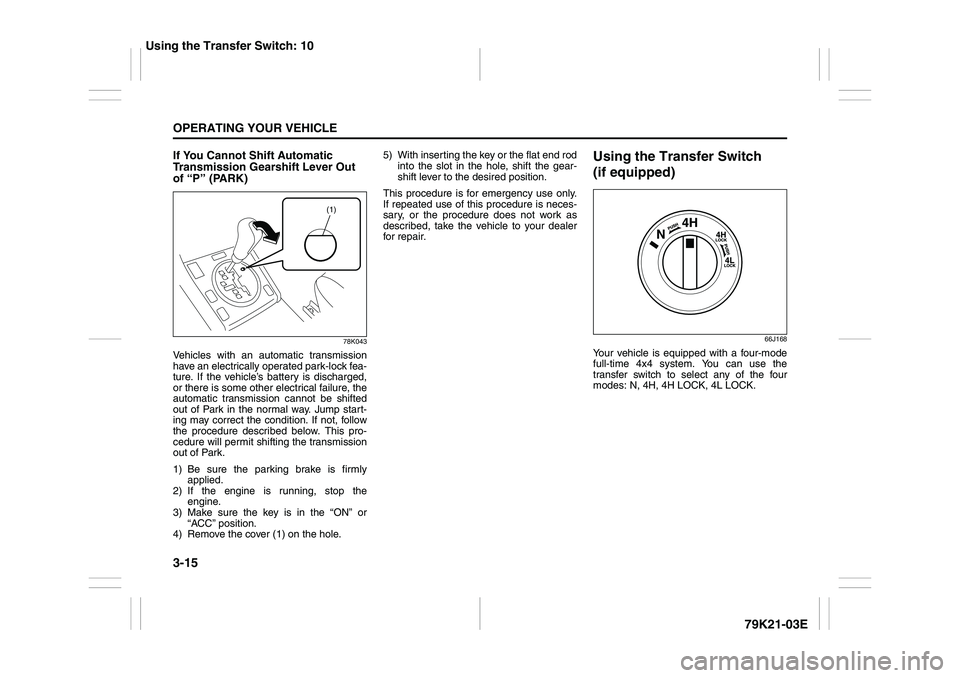
78K043
Vehicles with an automatic transmission
have an electrically operated park-lock fea-
ture. If the vehicle’s battery is discharged,
or there is some other electrical failure, the
automatic transmission cannot be shifted
out of Park in the normal way. Jump start-
ing may correct the condition. If not, follow
the procedure described below. This pro-
cedure will permit shifting the transmission
out of Park.
1) Be sure the parking brake is firmly
applied.
2) If the engine is running, stop the
engine.
3) Make sure the key is in the “ON” or
“ACC” position.
4) Remove the cover (1) on the hole.5) With inserting the key or the flat end rod
into the slot in the hole, shift the gear-
shift lever to the desired position.
This procedure is for emergency use only.
If repeated use of this procedure is neces-
sary, or the procedure does not work as
described, take the vehicle to your dealer
for repair.
Using the Transfer Switch
(if equipped)
66J168
Your vehicle is equipped with a four-mode
full-time 4x4 system. You can use the
transfer switch to select any of the four
modes: N, 4H, 4H LOCK, 4L LOCK.
(1)
Using the Transfer Switch: 10