door lock SUZUKI GRAND VITARA 2011 Owner's Guide
[x] Cancel search | Manufacturer: SUZUKI, Model Year: 2011, Model line: GRAND VITARA, Model: SUZUKI GRAND VITARA 2011Pages: 337, PDF Size: 6.21 MB
Page 235 of 337
5-82
OTHER CONTROLS AND EQUIPMENT
79K21-03E
Gate Operator / Canadian Program-
mingCanadian radio-frequency laws require
transmitter signals to “time-out” (or quit)
after several seconds of transmission –
which may not be long enough for
HomeLink
® to pick up the signal during
programming. Similar to this Canadian law,
some U.S. gate operators are designed to
“time-out” in the same manner.
If you live in Canada or you are having diffi-
culties programming a gate operator by
using the Programming procedures
(regardless of where you live), replace
“Programming HomeLink
®” step 3) with
the following:
NOTE:
If programming a garage door opener or
gate operator, it is advised to unplug the
device during the “cycling” process to pre-
vent possible overheating.
3) Continue to press and hold the
HomeLink
® button while you press and
release – every two seconds (“cycle”)
your hand-held transmitter until the fre-
quency signal has successfully been
accepted by HomeLink
®. (The indicator
light will flash slowly and then rapidly.)
Proceed with “Programming HomeLink
®”
step 4) to complete.
Using HomeLink
®
To operate, simply press and release the
programmed HomeLink
® button. Activation
will now occur for the trained device (i.e.
garage door opener, gate operator, secu-
rity system, entry door lock, home/office
lighting, etc.). For convenience, the hand-
held transmitter of the device may also be
used at any time. In the event that there
are still programming difficulties or ques-
tions, contact HomeLink
® at
www.homelink.com
or 1-800-355-3515.
Erasing HomeLink
® Buttons
To erase programming from the three but-
tons (individual buttons cannot be erased
but can be “reprogrammed” as outlined
below), follow the step noted:
Press and hold the two outer HomeLink
®
buttons until the indicator light begins to
flash-after 20 seconds. Release both but-
tons. Do not hold for longer that 30 sec-
onds. HomeLink
® is now in the train (or
learning) mode and can be programmed at
any time beginning with “Programming
HomeLink
®” – step 2).
Reprogramming a Single
HomeLink
® Button
To program a device to HomeLink
® using a
HomeLink
® button previously trained, fol-
low these steps:
1) Press and hold the desired HomeLink
®
button. DO NOT release the button.
2) The indicator light will begin to flash
after 20 seconds. Without releasing the
HomeLink
® button, proceed with “Pro-
gramming HomeLink
®” – step 2).
For questions or comments, contact
HomeLink
® at www.homelink.com
or 1-
800-355-3515.
Page 276 of 337
7-27INSPECTION AND MAINTENANCE
79K21-03E Tire Inflation Pressure
Tire inflation pressure should be
checked when the tire is cold. “Cold
tire inflation pressure” is the pressure
in a tire that has been driven less than
1 mile (1.6 km) or has been standing
for three hours or more.
54G307
The front, rear and spare tire pressure
specifications for your vehicle are
shown below and are listed on the Tire
and Loading Information Label, which
is located on the driver’s door lock pil-
lar. The Tire and Loading Information
Label contains the following informa-
tion:
Seating Capacity
Maximum Allowed Combined
Weight of Occupants and Cargo
Original Tire Size Recommended Cold Tire Inflation
Pressure of Original Tires
NOTE:
The tire inflation pressure will change
due to changes in atmospheric pres-
sure, temperature or tire temperature
when driving. To reduce the chance
that the low tire pressure warning light
will come on due to normal changes in
temperature and atmospheric pres-
sure, it is important to check and
adjust the tire pressures when the tires
are cold. Tires that appear to be at the
specified pressure when checked after
driving, when the tires are warm, could
have pressure below the specification
when the tires cool down. Also, tires
that are inflated to the specified pres-
sure in a warm garage may have pres-
sure below the specification when the
vehicle is driven outside in very coldtemperature. If you adjust the tire
pressure in a garage that is warmer
than the outside temperature, you
should add 1 psi to the recommended
cold tire inflation pressure for every
10°F difference between garage tem-
perature and outside temperature.
Measuring air pressure
Use the following steps to achieve
proper tire inflation:
1) Identify the recommended tire pres-
sure on the vehicle’s Tire and Load-
ing Information Label or in the
owner’s manual.
2) Remove the valve cap from the tire
valve stem.
3) Using a reliable pressure gauge,
measure the tire inflation pressure
by pressing the tire gauge firmly
onto the valve to get a pressure
measurement. Remember that
inflation pressures should be
checked when the tires are “cold”,
meaning before they have been
driven one mile or after sitting for
three hours or more allowing the
tire to cool to ambient air tempera-
ture.
4) If the air pressure is too high, slowly
release the air by pressing on the
tire valve stem with the edge of the
Recommended Cold Tire Inflation
Pressures
Front Tires230 kPa
33 psi
Rear Tires230 kPa
33 psi
Spare230 kPa
33 psi
Tires: 6
Page 286 of 337
7-37INSPECTION AND MAINTENANCE
79K21-03E
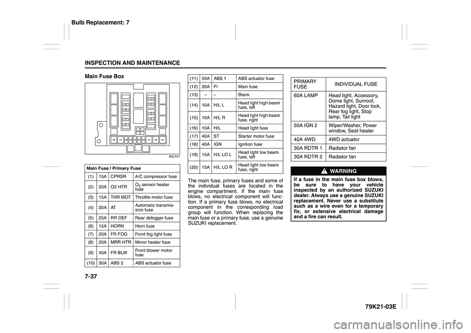
Main Fuse Box
64J157
The main fuse, primary fuses and some of
the individual fuses are located in the
engine compartment. If the main fuse
blows, no electrical component will func-
tion. If a primary fuse blows, no electrical
component in the corresponding load
group will function. When replacing the
main fuse or a primary fuse, use a genuine
SUZUKI replacement.
Main Fuse / Primary Fuse
(1) 15A CPRSR A/C compressor fuse
(2) 20A O2 HTRO
2 sensor heater
fuse
(3) 15A THR MOT Throttle motor fuse
(4) 20A ATAutomatic transmis-
sion fuse
(5) 25A RR DEF Rear defogger fuse
(6) 15A HORN Horn fuse
(7) 20A FR FOG Front fog light fuse
(8) 20A MRR HTR Mirror heater fuse
(9) 40A FR BLWFront blower motor
fuse
(10) 30A ABS 2 ABS actuator fuse
(11) 50A ABS 1 ABS actuator fuse
(12) 20A FI Main fuse
(13) – – Blank
(14) 10A H/L LHead light high beam
fuse, left
(15) 10A H/L RHead light high beam
fuse, right
(16) 10A H/L Head light fuse
(17) 40A ST Starter motor fuse
(18) 40A IGN Ignition fuse
(19) 15A H/L LO LHead light low beam
fuse, left
(20) 15A H/L LO RHead light low beam
fuse, right
PRIMARY
FUSEINDIVIDUAL FUSE
60A LAMP Head light, Accessory,
Dome light, Sunroof,
Hazard light, Door lock,
Rear fog light, Stop
lamp, Tail light
50A IGN 2 Wiper/Washer, Power
window, Seat heater
40A 4WD 4WD actuator
30A RDTR 1 Radiator fan
30A RDTR 2 Radiator fan
WARNING
If a fuse in the main fuse box blows,
be sure to have your vehicle
inspected by an authorized SUZUKI
dealer. Always use a genuine SUZUKI
replacement. Never use a substitute
such as a wire even for a temporary
fix, or extensive electrical damage
and a fire can result.
Bulb Replacement: 7
Page 287 of 337
7-38
INSPECTION AND MAINTENANCE
79K21-03E
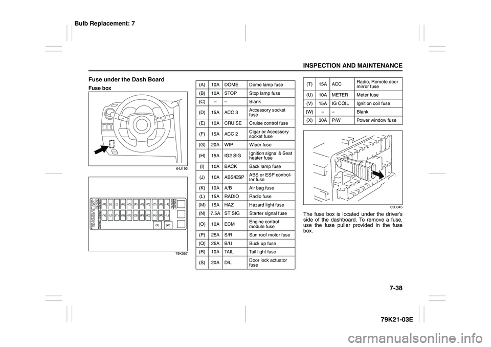
Fuse under the Dash BoardFuse box
64J192
79K05765D045
The fuse box is located under the driver’s
side of the dashboard. To remove a fuse,
use the fuse puller provided in the fuse
box.
SPARESPARE
SPARE
SPARE
USE THE DESIGNATED
FUSES AND RELAYS ONLYSPARE SPARE
(A)
(B)
(C)
(D)
(E)
(F)
(G)
(H)(I)
(J)
(L)
(M)
(N)
(O)
(P)
(Q)
(R)
(S)
(T)
(U)
(V)(K)
(W)
(X)
(A) 10A DOME Dome lamp fuse
(B) 10A STOP Stop lamp fuse
(C) – – Blank
(D) 15A ACC 3Accessory socket
fuse
(E) 10A CRUISE Cruise control fuse
(F) 15A ACC 2Cigar or Accessory
socket fuse
(G) 20A WIP Wiper fuse
(H) 15A IG2 SIGIgnition signal & Seat
heater fuse
(I) 10A BACK Back lamp fuse
(J) 10A ABS/ESPABS or ESP control-
ler fuse
(K) 10A A/B Air bag fuse
(L) 15A RADIO Radio fuse
(M) 15A HAZ Hazard light fuse
(N) 7.5A ST SIG Starter signal fuse
(O) 10A ECMEngine control
module fuse
(P) 25A S/R Sun roof motor fuse
(Q) 25A B/U Buck up fuse
(R) 10A TAIL Tail light fuse
(S) 20A D/LDoor lock actuator
fuse
(T) 15A ACCRadio, Remote door
mirror fuse
(U) 10A METER Meter fuse
(V) 15A IG COIL Ignition coil fuse
(W) – – Blank
(X) 30A P/W Power window fuse
Bulb Replacement: 7
Page 293 of 337
7-44
INSPECTION AND MAINTENANCE
79K21-03E
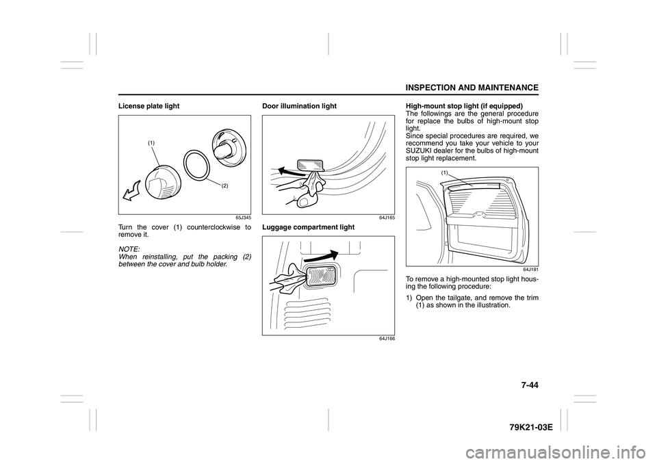
License plate light
65J345
Turn the cover (1) counterclockwise to
remove it.
NOTE:
When reinstalling, put the packing (2)
between the cover and bulb holder.Door illumination light
64J165
Luggage compartment light
64J166
High-mount stop light (if equipped)
The followings are the general procedure
for replace the bulbs of high-mount stop
light.
Since special procedures are required, we
recommend you take your vehicle to your
SUZUKI dealer for the bulbs of high-mount
stop light replacement.
64J181
To remove a high-mounted stop light hous-
ing the following procedure:
1) Open the tailgate, and remove the trim
(1) as shown in the illustration.
(1)
(2)
(1)
Page 319 of 337
10-2
GENERAL INFORMATION
79K21-03E
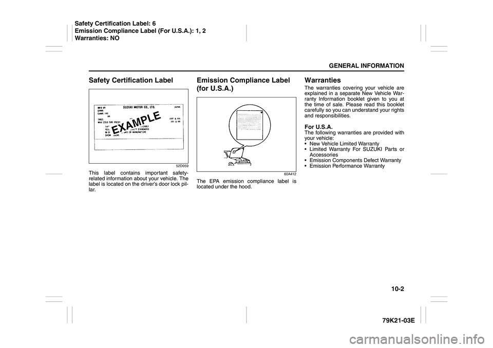
Safety Certification Label
52D059
This label contains important safety-
related information about your vehicle. The
label is located on the driver’s door lock pil-
lar.
Emission Compliance Label
(for U.S.A.)
60A412
The EPA emission compliance label is
located under the hood.
WarrantiesThe warranties covering your vehicle are
explained in a separate New Vehicle War-
ranty Information booklet given to you at
the time of sale. Please read this booklet
carefully so you can understand your rights
and responsibilities.For U.S.A.The following warranties are provided with
your vehicle:
New Vehicle Limited Warranty
Limited Warranty For SUZUKI Parts or
Accessories
Emission Components Defect Warranty
Emission Performance Warranty
Safety Certification Label: 6
Emission Compliance Label (For U.S.A.): 1, 2
Warranties: NO
Page 325 of 337
11-3
FUSES AND PROTECTED CIRCUITS
79K21-03E
79K057
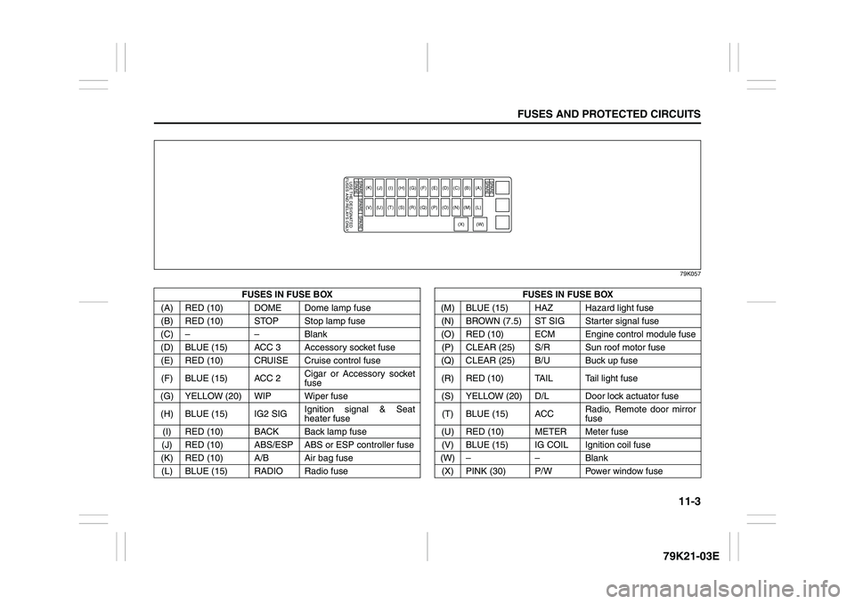
FUSES IN FUSE BOX FUSES IN FUSE BOX
(A) RED (10) DOME Dome lamp fuse (M) BLUE (15) HAZ Hazard light fuse
(B) RED (10) STOP Stop lamp fuse (N) BROWN (7.5) ST SIG Starter signal fuse
(C) – – Blank (O) RED (10) ECM Engine control module fuse
(D) BLUE (15) ACC 3 Accessory socket fuse(P) CLEAR (25) S/R Sun roof motor fuse
(E) RED (10) CRUISE Cruise control fuse (Q) CLEAR (25) B/U Buck up fuse
(F) BLUE (15) ACC 2Cigar or Accessory socket
fuse(R) RED (10) TAIL Tail light fuse
(G) YELLOW (20) WIP Wiper fuse (S) YELLOW (20) D/L Door lock actuator fuse
(H) BLUE (15) IG2 SIGIgnition signal & Seat
heater fuse(T) BLUE (15) ACCRadio, Remote door mirror
fuse
(I) RED (10) BACK Back lamp fuse (U) RED (10) METER Meter fuse
(J) RED (10) ABS/ESP ABS or ESP controller fuse (V) BLUE (15) IG COIL Ignition coil fuse
(K) RED (10) A/B Air bag fuse (W) – – Blank
(L) BLUE (15) RADIO Radio fuse (X) PINK (30) P/W Power window fuse
SPARESPARE
SPARE
SPARE
USE THE DESIGNATED
FUSES AND RELAYS ONLYSPARE SPARE
(A)
(B)
(C)
(D)
(E)
(F)
(G)
(H)(I)
(J)
(L)
(M)
(N)
(O)
(P)
(Q)
(R)
(S)
(T)
(U)
(V)(K)
(W)
(X)
Page 327 of 337
12-1
SPECIFICATIONS
79K21-03E
12
SPECIFICATIONSNOTE:
Specifications are subject to change with-
out notice.4WD: 4-wheel drive
2WD: 2-wheel driveM/T: Manual transmission
A/T: Automatic transmission
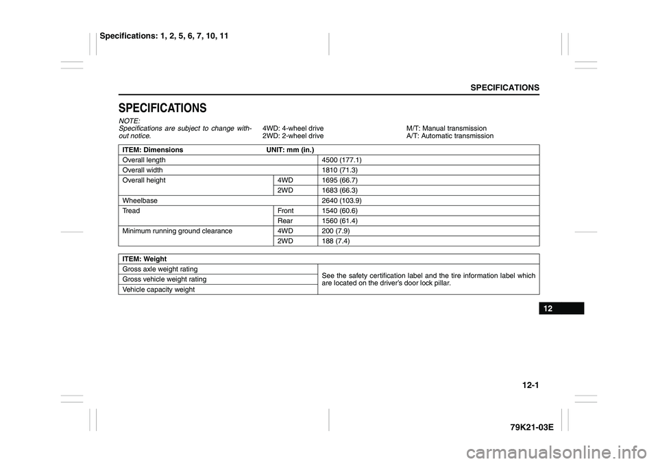
ITEM: Dimensions UNIT: mm (in.)
Overall length 4500 (177.1)
Overall width 1810 (71.3)
Overall height 4WD 1695 (66.7)
2WD 1683 (66.3)
Wheelbase 2640 (103.9)
Tread Front 1540 (60.6)
Rear 1560 (61.4)
Minimum running ground clearance 4WD 200 (7.9)
2WD 188 (7.4)
ITEM: Weight
Gross axle weight rating
See the safety certification label and the tire information label which
are located on the driver’s door lock pillar. Gross vehicle weight rating
Vehicle capacity weight
Specifications: 1, 2, 5, 6, 7, 10, 11
Page 329 of 337
12-3
SPECIFICATIONS
79K21-03E
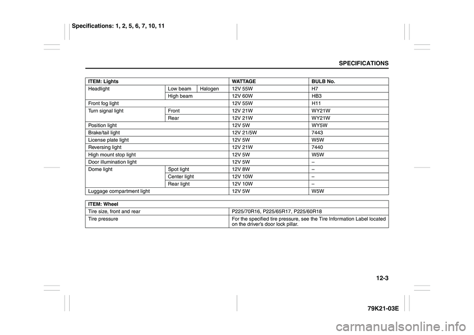
ITEM: Lights WATTAGE BULB No.
Headlight Low beam Halogen 12V 55W H7
High beam 12V 60W HB3
Front fog light 12V 55W H11
Turn signal light Front 12V 21W WY21W
Rear 12V 21W WY21W
Position light 12V 5W WY5W
Brake/tail light 12V 21/5W 7443
License plate light 12V 5W W5W
Reversing light 12V 21W 7440
High mount stop light 12V 5W W5W
Door illumination light 12V 5W –
Dome light Spot light 12V 8W –
Center light 12V 10W –
Rear light 12V 10W –
Luggage compartment light 12V 5W W5W
ITEM: Wheel
Tire size, front and rear P225/70R16, P225/65R17, P225/60R18
Tire pressure For the specified tire pressure, see the Tire Information Label located
on the driver’s door lock pillar.
Specifications: 1, 2, 5, 6, 7, 10, 11
Page 331 of 337
13-1
INDEX
13
79K21-03E
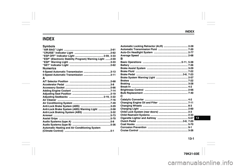
INDEXSymbols“AIR BAG” Light
..................................................................2-61
“CRUISE” Indicator Light
...................................................2-62
“ESP OFF” Indicator Light ........................................ 2-59
, 3-33
“ESP” (Electronic Stability Program) Warning Light
.......2-59
“ESP” Warning Light
...........................................................3-33
“SET” Indicator Light ..........................................................2-62
Numerics4-Speed Automatic Transmission
......................................3-13
5-Speed Automatic Transmission ......................................3-11
AA/T Selector Position
..........................................................2-68
Accelerator Pedal
................................................................3-8
Accessory Socket ................................................................5-66
Adding Engine Coolant
.......................................................7-14
Adjusting Seat Position ......................................................2-19
Adjusting Seatbacks
................................................. 2-19
, 2-22
Air Cleaner
...........................................................................7-16
Air Conditioning System
.....................................................7-49
Anti-Lock Brake System (ABS)
..........................................3-29
Anti-Lock Brake System (ABS) Warning Light
.................2-58
Anti-Lock Braking System (ABS)
.......................................3-32
Armrest
.................................................................................5-73
Assist Grips
.........................................................................5-70
Audio Systems (type A)
......................................................5-8
Audio Systems (type B) ......................................................5-36
Automatic Heating and Air Conditioning System
(Climate Control)
.................................................................5-1Automatic Locking Retractor (ALR)
.................................. 2-28
Automatic Transmission Fluid
.......................................... 7-20
Auto-On Headlight System
................................................ 2-77
Average Speed
.................................................................... 2-68
BBasic Operations
.......................................................5-11
, 5-38
Battery
.................................................................................. 7-36
Brake Assist System
.......................................................... 3-29
Brake Fluid
.......................................................................... 7-22
Brake Pedal ..................................................................3-8
, 7-23
Brake System Warning Light
............................................. 2-57
Brakes
.................................................................................. 7-22
Braking ................................................................................. 3-28
Break-In ................................................................................ 4-2
Brightness Control
............................................................. 2-66
Bulb Replacement ............................................................... 7-40
CCatalytic Converter
............................................................. 4-2
Changing Engine Oil and Filter
......................................... 7-11
Changing Wheels
................................................................ 8-3
Charging Light
.................................................................... 2-60
Child Lock System (rear doors)
......................................... 2-3
Child Restraint Systems
..................................................... 2-33
Cigarette Lighter and Ashtray
........................................... 5-67
Clutch Pedal
.................................................................3-8
, 7-20
Coat Hooks
.......................................................................... 5-70
Corrosion Prevention
......................................................... 9-1
Cruise Control
..................................................................... 3-26