F1 main SUZUKI GRAND VITARA 2012 Owners Manual
[x] Cancel search | Manufacturer: SUZUKI, Model Year: 2012, Model line: GRAND VITARA, Model: SUZUKI GRAND VITARA 2012Pages: 337, PDF Size: 6.21 MB
Page 292 of 337
7-43INSPECTION AND MAINTENANCE
79K21-03E
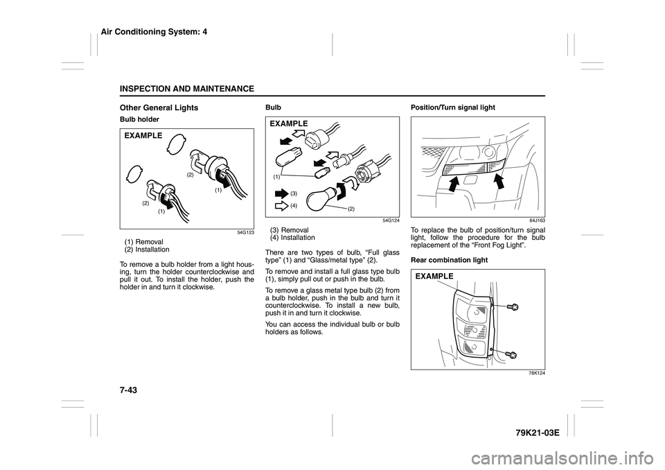
Other General LightsBulb holder
54G123
(1) Removal
(2) Installation
To remove a bulb holder from a light hous-
ing, turn the holder counterclockwise and
pull it out. To install the holder, push the
holder in and turn it clockwise.Bulb
54G124
(3) Removal
(4) Installation
There are two types of bulb, “Full glass
type” (1) and “Glass/metal type” (2).
To remove and install a full glass type bulb
(1), simply pull out or push in the bulb.
To remove a glass metal type bulb (2) from
a bulb holder, push in the bulb and turn it
counterclockwise. To install a new bulb,
push it in and turn it clockwise.
You can access the individual bulb or bulb
holders as follows.Position/Turn signal light
64J163
To replace the bulb of position/turn signal
light, follow the procedure for the bulb
replacement of the “Front Fog Light”.
Rear combination light
78K124
(1)
(1) (2)(2)
EXAMPLE
(1)
(2) (3)
(4)EXAMPLE
EXAMPLE
Air Conditioning System: 4
Page 293 of 337
7-44
INSPECTION AND MAINTENANCE
79K21-03E
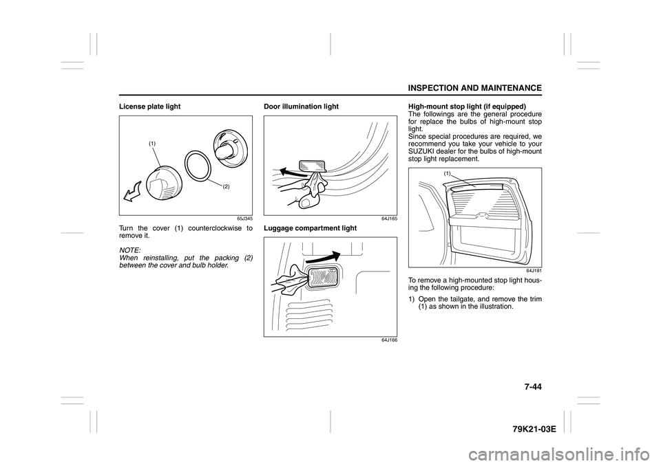
License plate light
65J345
Turn the cover (1) counterclockwise to
remove it.
NOTE:
When reinstalling, put the packing (2)
between the cover and bulb holder.Door illumination light
64J165
Luggage compartment light
64J166
High-mount stop light (if equipped)
The followings are the general procedure
for replace the bulbs of high-mount stop
light.
Since special procedures are required, we
recommend you take your vehicle to your
SUZUKI dealer for the bulbs of high-mount
stop light replacement.
64J181
To remove a high-mounted stop light hous-
ing the following procedure:
1) Open the tailgate, and remove the trim
(1) as shown in the illustration.
(1)
(2)
(1)
Page 294 of 337
7-45INSPECTION AND MAINTENANCE
79K21-03E
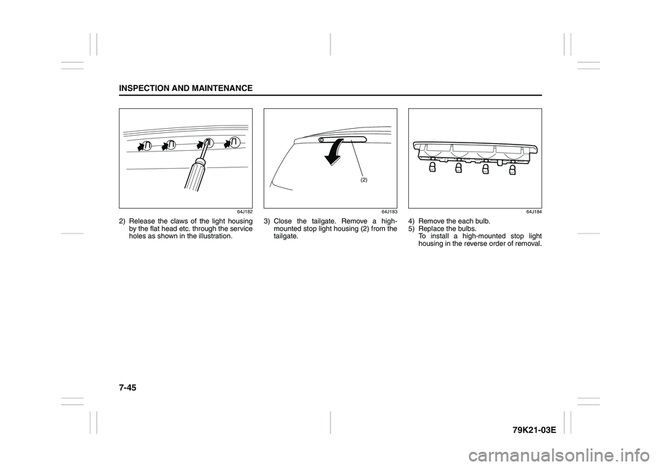
64J182
2) Release the claws of the light housing
by the flat head etc. through the service
holes as shown in the illustration.
64J183
3) Close the tailgate. Remove a high-
mounted stop light housing (2) from the
tailgate.
64J184
4) Remove the each bulb.
5) Replace the bulbs.
To install a high-mounted stop light
housing in the reverse order of removal.
(2)
Page 295 of 337

7-46
INSPECTION AND MAINTENANCE
79K21-03E
Wiper Blades
54G129
If the wiper blades become brittle or dam-
aged, or make streaks when wiping,
replace the wiper blades.
To install new wiper blades, follow the pro-
cedures below.
NOTE:
Some wiper blades may be different from
the ones described here depending on
vehicle specifications. If so, consult your
SUZUKI dealer for proper replacement
method.For windshield wipers:
70G119
1) Hold the wiper arm away from the win-
dow.
52D102
2) Squeeze lock lever (1) towards wiper
arm (2) and remove the wiper frame
from the arm as shown.
CAUTION
To avoid scratching or breaking the
window, do not let the wiper arm
strike the window while replacing the
wiper blade.
Page 296 of 337

7-47INSPECTION AND MAINTENANCE
79K21-03E
60A260
3) Pull the locked end of the wiper blade
firmly to unlock the blade and slide the
blade out as shown.
52D124
(3) Retainer
4) If the new blade is provided without the
two metal retainers, move them from
the old blade to the new one.Installation
52D125
(4) Locked end
5) Install the new blade in the reverse
order of removal, with the locked end
positioned toward the wiper arm. Make
sure the blade is properly retained by
all the hooks. Grasp the blade near the
locked end and pull in the direction of
the arrows to lock the end into place.
6) Reinstall wiper frame to arm, making
sure that the lock lever is snapped
securely into the arm.
Page 297 of 337

7-48
INSPECTION AND MAINTENANCE
79K21-03E
For rear wipers:
80G146
1) Hold the wiper arm away from the win-
dow.
2) Remove the wiper frame from the arm
as shown.
3) Slide the blade out as shown.
65D151
NOTE:
Do not flex the wiper blade frame end more
than necessary. If you do, it can break off.
54G135
(1) Retainer
4) If the new blade is provided without the
two metal retainers, move them from
the old blade to the new one.
5) Install the new blade in the reverse
order of removal.
Make sure the blade is properly
retained by all the hooks.
6) Reinstall wiper frame to arm in the
reverse order of removal.
Page 298 of 337
7-49INSPECTION AND MAINTENANCE
79K21-03E
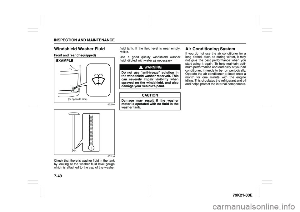
Windshield Washer FluidFront and rear (if equipped)
66J008
66J116
Check that there is washer fluid in the tank
by looking at the washer fluid level gauge
which is attached to the cap of the washerfluid tank. If the fluid level is near empty,
refill it.
Use a good quality windshield washer
fluid, diluted with water as necessary.
Air Conditioning SystemIf you do not use the air conditioner for a
long period, such as during winter, it may
not give the best performance when you
start using it again. To help maintain opti-
mum performance and durability of your air
conditioner, it needs to be run periodically.
Operate the air conditioner at least once a
month for one minute with the engine
idling. This circulates the refrigerant and oil
and helps protect the internal components.
(or opposite side)
EXAMPLE
WARNING
Do not use “anti-freeze” solution in
the windshield washer reservoir. This
can severely impair visibility when
sprayed on the windshield, and also
damage your vehicle’s paint.
CAUTION
Damage may result if the washer
motor is operated with no fluid in the
washer tank.
Page 302 of 337
8-3EMERGENCY SERVICE
79K21-03E
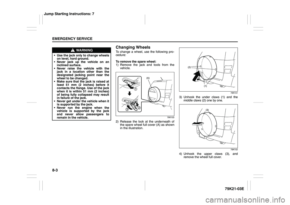
Changing WheelsTo change a wheel, use the following pro-
cedure:
To remove the spare wheel:
1) Remove the jack and tools from the
vehicle.
78K150
2) Release the lock at the underneath of
the spare wheel full cover (A) as shown
in the illustration.
78K151
3) Unhook the under claws (1) and the
middle claws (2) one by one.
78K152
4) Unhook the upper claws (3), and
remove the wheel full cover.
WARNING
Use the jack only to change wheels
on level, hard ground.
Never jack up the vehicle on an
inclined surface.
Never raise the vehicle with the
jack in a location other than the
designated jacking point near the
wheel to be changed.
Make sure that the jack is raised at
least 51 mm (2 inches) before it
contacts the flange. Use of the jack
when it is within 51 mm (2 inches)
of being fully collapsed may result
in failure of the jack.
Never get under the vehicle when it
is supported by the jack.
Never run the engine when the
vehicle is supported by the jack
and never allow passengers to
remain in the vehicle.
(A)
(1) (2)(3)
Jump Starting Instructions: 7
Page 306 of 337
8-7EMERGENCY SERVICE
79K21-03E
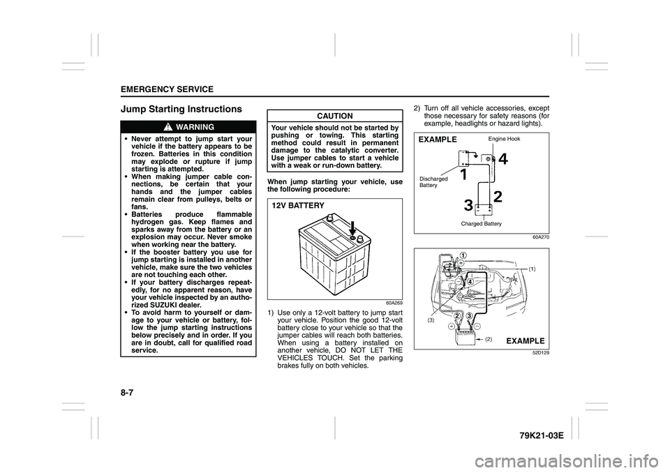
Jump Starting Instructions
When jump starting your vehicle, use
the following procedure:
60A269
1) Use only a 12-volt battery to jump start
your vehicle. Position the good 12-volt
battery close to your vehicle so that the
jumper cables will reach both batteries.
When using a battery installed on
another vehicle, DO NOT LET THE
VEHICLES TOUCH. Set the parking
brakes fully on both vehicles.2) Turn off all vehicle accessories, except
those necessary for safety reasons (for
example, headlights or hazard lights).
60A270
52D129
WARNING
Never attempt to jump start your
vehicle if the battery appears to be
frozen. Batteries in this condition
may explode or rupture if jump
starting is attempted.
When making jumper cable con-
nections, be certain that your
hands and the jumper cables
remain clear from pulleys, belts or
fans.
Batteries produce flammable
hydrogen gas. Keep flames and
sparks away from the battery or an
explosion may occur. Never smoke
when working near the battery.
If the booster battery you use for
jump starting is installed in another
vehicle, make sure the two vehicles
are not touching each other.
If your battery discharges repeat-
edly, for no apparent reason, have
your vehicle inspected by an autho-
rized SUZUKI dealer.
To avoid harm to yourself or dam-
age to your vehicle or battery, fol-
low the jump starting instructions
below precisely and in order. If you
are in doubt, call for qualified road
service.
CAUTION
Your vehicle should not be started by
pushing or towing. This starting
method could result in permanent
damage to the catalytic converter.
Use jumper cables to start a vehicle
with a weak or run-down battery.12V BATTERY
EXAMPLE
Engine Hook
Charged Battery
Discharged
Battery
EXAMPLE
Page 307 of 337
8-8
EMERGENCY SERVICE
79K21-03E
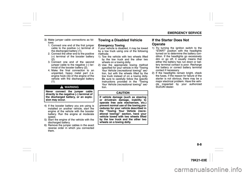
3) Make jumper cable connections as fol-
lows:
1. Connect one end of the first jumper
cable to the positive (+) terminal of
the discharged battery (1).
2. Connect the other end to the positive
(+) terminal of the booster battery
(2).
3. Connect one end of the second
jumper cable to the negative (–) ter-
minal of the booster battery (2).
4. Make the final connection to an
unpainted, heavy metal part (i.e.
engine hook (3)) of the engine of the
vehicle with the discharged battery
(1).
4) If the booster battery you are using is
installed on another vehicle, start the
engine of the vehicle with the booster
battery. Run the engine at moderate
speed.
5) Start the engine of the vehicle with the
discharged battery.
6) Remove the jumper cables in the exact
reverse order in which you connected
them.
Towing a Disabled VehicleEmergency TowingIf your vehicle is disabled, it may be towed
by a tow truck using one of the following
methods:
1) Tow the vehicle with two wheels lifted
by the tow truck and the other two
wheels on a towing dolly.
2) Use the appropriate towing method
specified for your vehicle in the “Towing
Your Vehicle (recreational towing)” sec-
tion, but with the wheels lifted by the
tow truck instead of on a towing dolly.
Be sure to carefully follow the specific
instructions provided in the “Towing
Your Vehicle (recreational towing)” sec-
tion.
If the Starter Does Not
Operate1) Try turning the ignition switch to the
“START” position with the headlights
turned on to determine the battery con-
dition. If the headlights go excessively
dim or go off, it usually means that
either the battery has run down or bat-
tery terminal contact is poor. Recharge
the battery or correct battery terminal
contact if necessary.
2) If the headlights remain bright, check
the fuses. If the reason for failure of the
starter is not obvious, there may be a
major electrical problem. Have the vehi-
cle inspected by your authorized
SUZUKI dealer.
WARNING
Never connect the jumper cable
directly to the negative (–) terminal of
the discharged battery, or an explo-
sion may occur.
CAUTION
If vehicle damage (such as steering
or drivetrain damage, inability to
operate free axle mechanism, etc.)
prevent normal use of the towing pro-
cedures for your vehicle described in
the “Towing Your Vehicle (recre-
ational towing)” section, have your
vehicle towed with two wheels lifted
by the tow truck and the other two
wheels on a towing dolly.