clock SUZUKI GRAND VITARA 2020 User Guide
[x] Cancel search | Manufacturer: SUZUKI, Model Year: 2020, Model line: GRAND VITARA, Model: SUZUKI GRAND VITARA 2020Pages: 482, PDF Size: 21 MB
Page 264 of 482
5-22
OTHER CONTROLS AND EQUIPMENT
54P00-01E
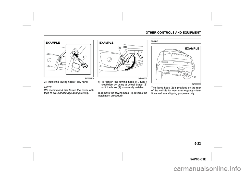
54P000529
3) Install the towing hook (1) by hand.
NOTE:
We recommend that fasten the cover with
tape to prevent damage during towing.
54P000530
4) To tighten the towing hook (1), turn it
clockwise by using a wheel brace (B)
until the hook (1) is securely installed.
To remove the towing hook (1), reverse the
installation procedure.
Rear
54P000802
The frame hook (2) is provided on the rear
of the vehicle for use in emergency situa-
tions and sea shipping purposes only.
(1)
EXAMPLE
(B)(1)
EXAMPLE
(2)
EXAMPLE
Page 281 of 482
5-39
OTHER CONTROLS AND EQUIPMENT
54P00-01E
The radio antenna on the roof is remov-
able. To remove the antenna, turn it coun-
terclockwise. To reinstall the antenna, turn
it clockwise firmly by hand.Installation of radio frequency
transmitters
NOTE:
When you intend to use Radio Frequency
(RF) transmitting equipment in your vehi-
cle, refer to “Installation of radio frequency
(RF) transmitting equipment” in the end of
this book.NOTICE
To avoid damage to the radio
antenna:
• Remove the antenna when using an
automatic car wash.
• Remove the antenna when the
antenna hits anything such as a
low ceiling in a parking garage or
putting a car cover over your vehi-
cle.
NOTICE
Improper installation of mobile com-
munication equipment such as cellu-
lar telephones, CB (Citizen’s Band)
radios or any other wireless transmit-
ters may cause electronic interfer-
ence with your vehicle’s ignition
system, resulting in vehicle perfor-
mance problems. Consult your
SUZUKI dealer or qualified service
technician for advice.
Page 290 of 482
5-48
OTHER CONTROLS AND EQUIPMENT
54P00-01E
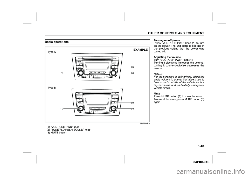
Basic operations
84MM00516
(1) “VOL PUSH PWR” knob
(2) “TUNE/FLD PUSH SOUND” knob
(3) MUTE button
(2)
(3)
(1)
(2)
(3)
(1)
Type A
Type BEXAMPLE
Turning on/off power
Press “VOL PUSH PWR” knob (1) to turn
on the power. The unit starts to operate in
the previous setting that the power was
turned off.
Adjusting the volume
Turn “VOL PUSH PWR” knob (1).
Turning it clockwise increases the volume;
turning it counterclockwise decreases the
volume.
NOTE:
For the purposes of safe driving, adjust the
audio volume to a level that allows you to
hear sounds outside of the vehicle includ-
ing car horns and particularly emergency
vehicle sirens.
Mute
Press MUTE button (3) to mute the sound.
To cancel the mute, press MUTE button (3)
again.
Page 313 of 482
5-71
OTHER CONTROLS AND EQUIPMENT
54P00-01E
Phone registration
NOTE:
• Up to 5 phones can be registered.
To set up a new phone, disconnect the
audio player from the unit. Connect the
audio player again after phone setup is
completed if necessary.
When attempts to establish the pairing
fail within 120 seconds, the connecting
operation will be canceled. Try to estab-
lish the pairing again or refer to the man-
ual of the phone in use for how to
establish the pairing with the phone.
1) Press the Bluetooth
® setup button (4).
The Bluetooth® setup menu will be dis-
played.
2) Turn “TUNE/FLD PUSH SOUND” knob
(1) to select “Setup Bluetooth”, and
press the knob (1) to determine the
selection.
3) Turn “TUNE/FLD PUSH SOUND” knob
(1) to select “Pairing”, and press the
knob (1) to determine the selection.
4) Select “CAR AUDIO” from the Blue-
tooth
® menu of the phone and establish
the pairing.
Refer to the manual of the phone in use
for further information.
5) Enter the passkey displayed on the unit
to the phone.
6) Press ON HOOK button (6).NOTE:
When selecting “Go Back”, the previous
menu will be displayed.
When registering an additional phone,
repeat Step from 1).
Receiving a call
Press OFF HOOK button (5) to receive a
call.
Ending a call
Press ON HOOK button (6) to end a call.
Rejecting a call (only for supported
models)
Press ON HOOK button (6) to reject a
incoming call.
Adjusting the listening volume
Turn “VOL PUSH PWR” knob (2) during
a call.
Turning it clockwise increases the vol-
ume; turning it counterclockwise
decreases the volume.
Press “VOL” switch (7) during a call.
Pressing “+” of the switch increases the
volume; pressing “-” of the switch
decreases the volume.Adjusting the ring volume
Turn “VOL PUSH PWR” knob (2) while a
call is coming in.
Turning it clockwise increases the vol-
ume; turning it counterclockwise
decreases the volume.
Press “VOL” switch (7) during a call.
Pressing “+” of the switch increases the
volume; pressing “-” of the switch
decreases the volume.
Adjusting the call or ringtone volume
Follow the instructions below to adjust the
call or ringtone volume.
1) Press the Bluetooth
® setup button (4).
The Bluetooth® setup menu will be dis-
played.
2) Turn “TUNE/FLD PUSH SOUND” knob
(1) to select “Setup Telephone”, and
press the knob (1) to determine the
selection.
3) Turn “TUNE/FLD PUSH SOUND” knob
(1) to select “Sound Setting”, and press
the knob (1) to determine the selection.
4) Turn “TUNE/FLD PUSH SOUND” knob
(1) to select “Call Volume” or “Ringtone
Volume”, and press the knob (1) to
determine the selection.
The current call or ringtone volume will
be displayed.
5) Turn “TUNE/FLD PUSH SOUND” knob
(1) to select the desired call or ringtone
volume, and press the knob (1) to
determine the selection.
To use the hands-free function with this
unit, it is required to register the phone
in advance.
Page 362 of 482
7-24
INSPECTION AND MAINTENANCE
54P00-01E
5) Reinstall the drain plug and gasket.
Tighten the plug with a wrench to the
specified torque.
NOTE:
• Whenever the engine oil is changed, the
oil life monitoring must be reset to moni-
tor the next oil change timing properly.
To reset the light, consult your SUZUKI
dealer. If you reset it by yourself, refer to
“Setting mode” in “BEFORE DRIVING”
section (for gasoline engine model).
• For more information of the oil change
request light and oil life monitoring, refer
to “Oil change request light (if equipped)”
and “Information display” in “BEFORE
DRIVING” section.
Oil filter replacement
NOTE:
(For diesel engine model)
Since special procedures and tools are
required, ask your authorized SUZUKI
dealer for this job.
1) Using an oil filter wrench, turn the oil fil-
ter counterclockwise and remove it.
2) Using a clean rag, wipe off the mount-
ing surface on the engine where the
new filter will be seated.
3) Smear a small amount of engine oil
around the rubber gasket of the new oil
filter.
4) Screw the new filter by hand until the fil-
ter gasket contacts the mounting sur-
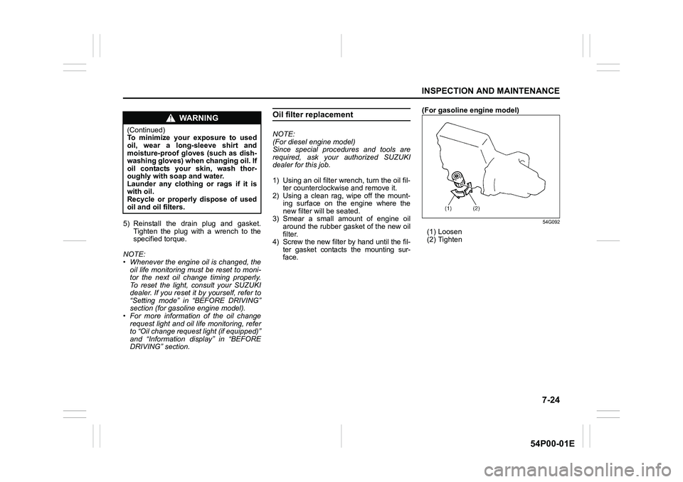
face.(For gasoline engine model)
54G092
(1) Loosen
(2) Tighten
WA R N I N G
(Continued)
To minimize your exposure to used
oil, wear a long-sleeve shirt and
moisture-proof gloves (such as dish-
washing gloves) when changing oil. If
oil contacts your skin, wash thor-
oughly with soap and water.
Launder any clothing or rags if it is
with oil.
Recycle or properly dispose of used
oil and oil filters.
Page 366 of 482
7-28
INSPECTION AND MAINTENANCE
54P00-01E
If the coolant level is below “LOW” mark,
more coolant should be added. When the
engine is cool, remove the degassing tank
cap by turning it counterclockwise slowly to
release any pressure. And add coolant
until the degassing tank level reaches
“FULL” mark. Never fill the degassing tank
above “FULL” mark.
Coolant replacement
Since special procedures are required, ask
your authorized SUZUKI dealer for this job.
Air cleaner
If the air cleaner is clogged with dust, there
will be greater intake resistance, resulting
in decreased power output and increased
fuel consumption.
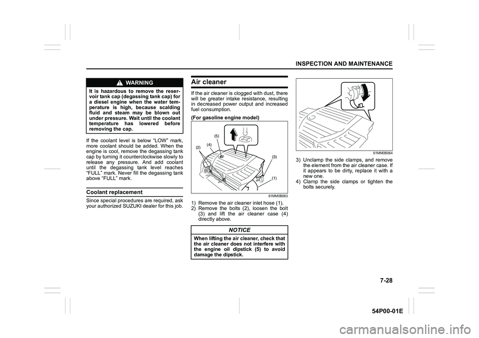
(For gasoline engine model)
61MM0B063
1) Remove the air cleaner inlet hose (1).
2) Remove the bolts (2), loosen the bolt
(3) and lift the air cleaner case (4)
directly above.
61MM0B064
3) Unclamp the side clamps, and remove
the element from the air cleaner case. If
it appears to be dirty, replace it with a
new one.
4) Clamp the side clamps or tighten the
bolts securely.
WA R N I N G
It is hazardous to remove the reser-
voir tank cap (degassing tank cap) for
a diesel engine when the water tem-
perature is high, because scalding
fluid and steam may be blown out
under pressure. Wait until the coolant
temperature has lowered before
removing the cap.
NOTICE
When lifting the air cleaner, check that
the air cleaner does not interfere with
the engine oil dipstick (5) to avoid
damage the dipstick.
(4)(5)
(1) (2)
(3)
Page 383 of 482
7-45
INSPECTION AND MAINTENANCE
54P00-01E
Bulb replacementHeadlights
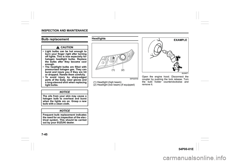
54P000709
(1) Headlight (high beam)
(2) Headlight (low beam) (if equipped)
80JM071
Open the engine hood. Disconnect the
coupler by pushing the lock release. Turn
the bulb holder counterclockwise and
remove it.
CAUTION
• Light bulbs can be hot enough to
burn your finger right after turning
off lights. This is true especially for
halogen headlight bulbs. Replace
the bulbs after they become cool
enough.
• The headlight bulbs are filled with
pressurized halogen gas. They can
burst and injure you if they are hit
or dropped. Handle them carefully.
• To avoid injury by sharp-edged
parts of the body, wear gloves and
a long-sleeved shirt when replacing
light bulbs.
NOTICE
The oils from your skin may cause a
halogen bulb to overheat and burst
when the lights are on. Grasp a new
bulb with a clean cloth.
NOTICE
Frequent bulb replacement indicates
the need for an inspection of the elec-
trical system. This should be carried
out by your SUZUKI dealer.
(1) (2)
EXAMPLE
Page 384 of 482
7-46
INSPECTION AND MAINTENANCE
54P00-01E
Side turn signal light (if equipped)
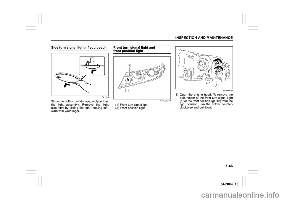
64J195
Since the bulb is built-in type, replace it as
the light assembly. Remove the light
assembly by sliding the light housing left-
ward with your finger.
Front turn signal light and front position light
54P000710
(1) Front turn signal light
(2) Front position light
54P000711
1) Open the engine hood. To remove the
bulb holder of the front turn signal light
(1) or the front position light (2) from the
light housing, turn the holder counter-
clockwise and pull it out.
(1)(2)
(1) (2)
Page 385 of 482
7-47
INSPECTION AND MAINTENANCE
54P00-01E
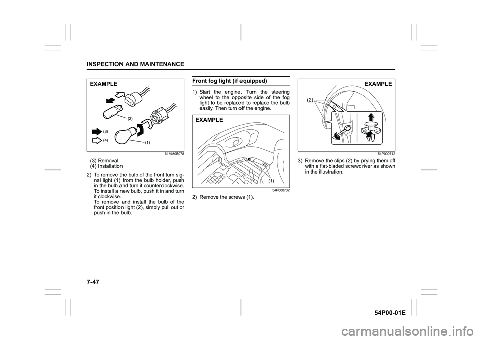
61MM0B078
(3) Removal
(4) Installation
2) To remove the bulb of the front turn sig-
nal light (1) from the bulb holder, push
in the bulb and turn it counterclockwise.
To install a new bulb, push it in and turn
it clockwise.
To remove and install the bulb of the
front position light (2), simply pull out or
push in the bulb.
Front fog light (if equipped)
1) Start the engine. Turn the steering
wheel to the opposite side of the fog
light to be replaced to replace the bulb
easily. Then turn off the engine.
54P000732
2) Remove the screws (1).
54P000712
3) Remove the clips (2) by prying them off
with a flat-bladed screwdriver as shown
in the illustration.
(2)
(1) (3)
(4)
EXAMPLE
(1)
EXAMPLE
(2)
EXAMPLE
Page 386 of 482
7-48
INSPECTION AND MAINTENANCE
54P00-01E
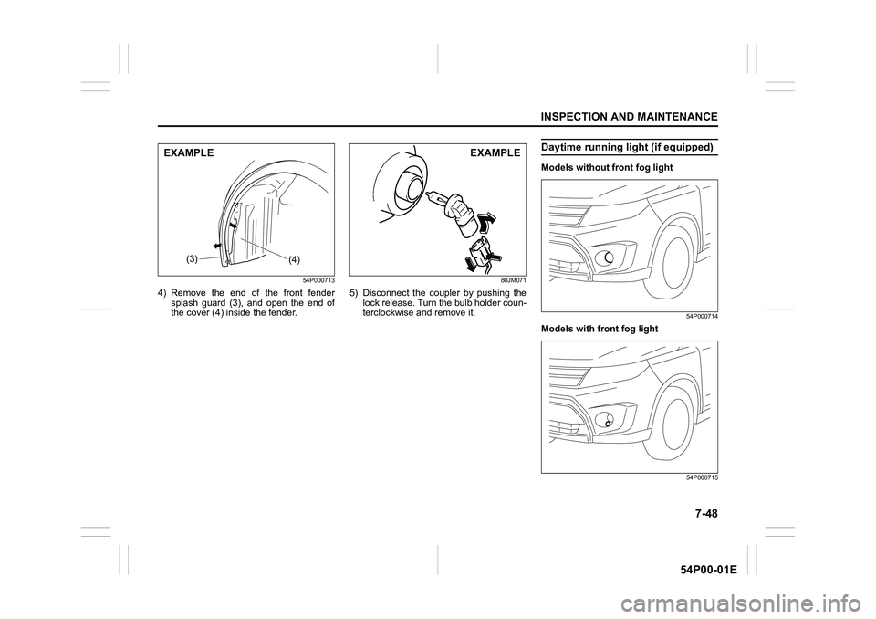
54P000713
4) Remove the end of the front fender
splash guard (3), and open the end of
the cover (4) inside the fender.
80JM071
5) Disconnect the coupler by pushing the
lock release. Turn the bulb holder coun-
terclockwise and remove it.
Daytime running light (if equipped)
Models without front fog light
54P000714
Models with front fog light
54P000715
(3)(4)
EXAMPLEEXAMPLE