steering wheel SUZUKI GRAND VITARA 2020 Owner's Manual
[x] Cancel search | Manufacturer: SUZUKI, Model Year: 2020, Model line: GRAND VITARA, Model: SUZUKI GRAND VITARA 2020Pages: 482, PDF Size: 21 MB
Page 238 of 482
4-4
DRIVING TIPS
54P00-01E
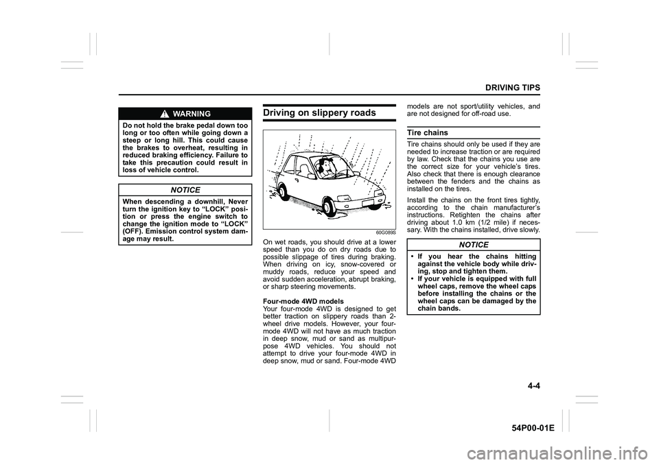
Driving on slippery roads
60G089S
On wet roads, you should drive at a lower
speed than you do on dry roads due to
possible slippage of tires during braking.
When driving on icy, snow-covered or
muddy roads, reduce your speed and
avoid sudden acceleration, abrupt braking,
or sharp steering movements.
Four-mode 4WD models
Your four-mode 4WD is designed to get
better traction on slippery roads than 2-
wheel drive models. However, your four-
mode 4WD will not have as much traction
in deep snow, mud or sand as multipur-
pose 4WD vehicles. You should not
attempt to drive your four-mode 4WD in
deep snow, mud or sand. Four-mode 4WDmodels are not sport/utility vehicles, and
are not designed for off-road use.
Tire chains
Tire chains should only be used if they are
needed to increase traction or are required
by law. Check that the chains you use are
the correct size for your vehicle’s tires.
Also check that there is enough clearance
between the fenders and the chains as
installed on the tires.
Install the chains on the front tires tightly,
according to the chain manufacturer’s
instructions. Retighten the chains after
driving about 1.0 km (1/2 mile) if neces-
sary. With the chains installed, drive slowly.
WA R N I N G
Do not hold the brake pedal down too
long or too often while going down a
steep or long hill. This could cause
the brakes to overheat, resulting in
reduced braking efficiency. Failure to
take this precaution could result in
loss of vehicle control.
NOTICE
When descending a downhill, Never
turn the ignition key to “LOCK” posi-
tion or press the engine switch to
change the ignition mode to “LOCK”
(OFF). Emission control system dam-
age may result.
NOTICE
• If you hear the chains hitting
against the vehicle body while driv-
ing, stop and tighten them.
• If your vehicle is equipped with full
wheel caps, remove the wheel caps
before installing the chains or the
wheel caps can be damaged by the
chain bands.
Page 279 of 482
5-37
OTHER CONTROLS AND EQUIPMENT
54P00-01E
You can use the air conditioning switch (6)
to manually turn the air conditioner on or off
according to your preference. When you
turn the air conditioning switch off, the cli-
mate control system cannot lower the inside
temperature below outside temperature.
To turn the climate control system off, push
“OFF” switch (7).
NOTE:
If “AUTO” on the display blinks, there is a
problem in the heating system and/or air
conditioning system. You should have the
system inspected by an authorized
SUZUKI dealer.
NOTE:
• To find the temperature at which you are
most comfortable, start with the 22°C
(72°F) or 25°C (75°F) setting. (the tem-
perature vary depending on vehicle
specifications.).
• If you turn the temperature selector (1)
until “HI” or “LO” appears on the display,
the climate control system will operate at
maximum heating or cooling and the
blower will run at full speed.
• To avoid blowing cold air in cold weather
or hot air in hot weather, the system will
delay turning on the blower until warmed
or chilled air is available.
• If your vehicle has been left in the sun
with the windows closed, it will cool
faster if you open the windows briefly.
• Even under the automatic operation, you
can set individual selectors to the manualmode. The manually selected functions
are maintained, and the other functions
remain under automatic operation.
• If the windshield and/or the front door
windows are fogged, push the defrost
switch (5) to turn on the defroster, or
push the air flow selector (4) to change
the air flow to HEAT & DEFROST posi-
tion to defog the windows.
• To return the blower speed selector (2),
air intake selector (3), and air flow selec-
tor (4) to automatic operation, push
“AUTO” switch (8).
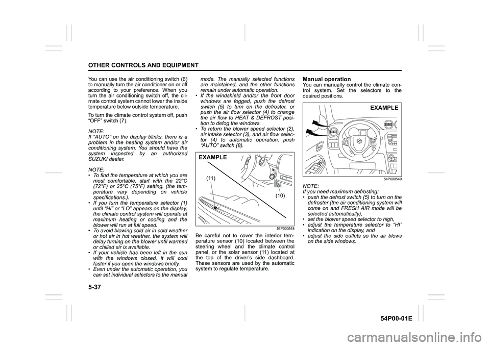
54P000548
Be careful not to cover the interior tem-
perature sensor (10) located between the
steering wheel and the climate control
panel, or the solar sensor (11) located at
the top of the driver’s side dashboard.
These sensors are used by the automatic
system to regulate temperature.
Manual operationYou can manually control the climate con-
trol system. Set the selectors to the
desired positions.
54P000540
NOTE:
If you need maximum defrosting:
• push the defrost switch (5) to turn on the
defroster (the air conditioning system will
come on and FRESH AIR mode will be
selected automatically),
• set the blower speed selector to high,
• adjust the temperature selector to “HI”
indication on the display, and
• adjust the side outlets so the air blows
on the side windows.
(10) (11)
EXAMPLE
EXAMPLE
Page 323 of 482
5-81
OTHER CONTROLS AND EQUIPMENT
54P00-01E
Deletion of audio device information
(Delete Audio)
Follow the instructions below to delete the
registered audio device information.
1) Press the Bluetooth
® setup button (6).
The Bluetooth® setup menu will be dis-
played.
2) Turn “TUNE/FLD PUSH SOUND” knob
(2) to select “Setup Bluetooth”, and
press the knob (2) to determine the
selection.
3) Turn “TUNE/FLD PUSH SOUND” knob
(2) to select “List Audio”, and press the
knob (2) to determine the selection.
4) Turn “TUNE/FLD PUSH SOUND” knob
(2) to select an audio device to be
deleted, and press the knob (2) to
determine the selection.
5) Turn “TUNE/FLD PUSH SOUND” knob
(2) to select “Delete”, and press the
knob (2) to determine the selection.
6) Turn “TUNE/FLD PUSH SOUND” knob
(2) to select “Delete?”, and press the
knob (2) to determine the selection.
7) Turn “TUNE/FLD PUSH SOUND” knob
(2) to select “Confirm”, and press the
knob (2) to complete the deletion.
NOTE:
When selecting “Go Back”, the previous
menu will be displayed.
Disclaimer for Bluetooth® function
• Depending on compatibility of mobile
phone models, no Bluetooth® function
can be used, or some Bluetooth® func-
tions may be restricted.
• Connectivity or voice quality may get
affected depending on circumstances.
• After the ignition switch is turned to “ON”
position or the engine switch is pressed
to change the ignition mode to “ON”, the
audio system takes few seconds to
detect and connect to the Bluetooth
®
device (if already paired).
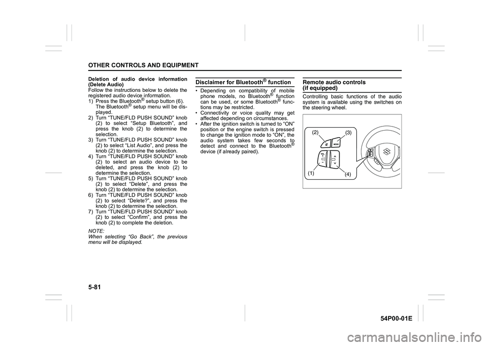
Remote audio controls(if equipped)
Controlling basic functions of the audio
system is available using the switches on
the steering wheel.
(2)(3)
(1)
(4)
Page 344 of 482
7-6
INSPECTION AND MAINTENANCE
54P00-01E
NOTE:
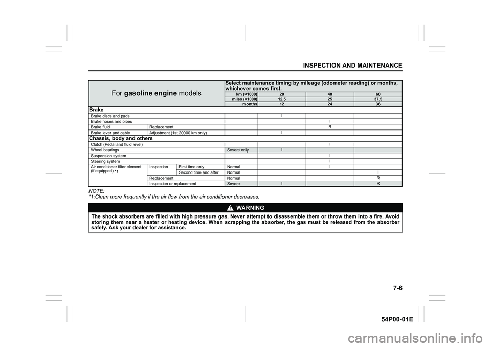
*1:Clean more frequently if the air flow from the air conditioner decreases.
For gasoline engine models
Select maintenance timing by mileage (odometer reading) or months,
whichever comes first.
km (×1000)204060miles (×1000)12.52537.5months122436Brake
Brake discs and padsI
Brake hoses and pipesI
Brake fluid ReplacementR
Brake lever and cable Adjustment (1st 20000 km only)I
Chassis, body and others
Clutch (Pedal and fluid level)I
Wheel bearingsSevere onlyI
Suspension systemI
Steering systemI
Air conditioner filter element
(if equipped)
*1Inspection First time only NormalI
Second time and after NormalI
Replacement NormalR
Inspection or replacement
SevereIR
WA R N I N G
The shock absorbers are filled with high pressure gas. Never attempt to disassemble them or throw them into a fire. Avoid
storing them near a heater or heating device. When scrapping the absorber, the gas must be released from the absorber
safely. Ask your dealer for assistance.
Page 348 of 482
7-10
INSPECTION AND MAINTENANCE
54P00-01E
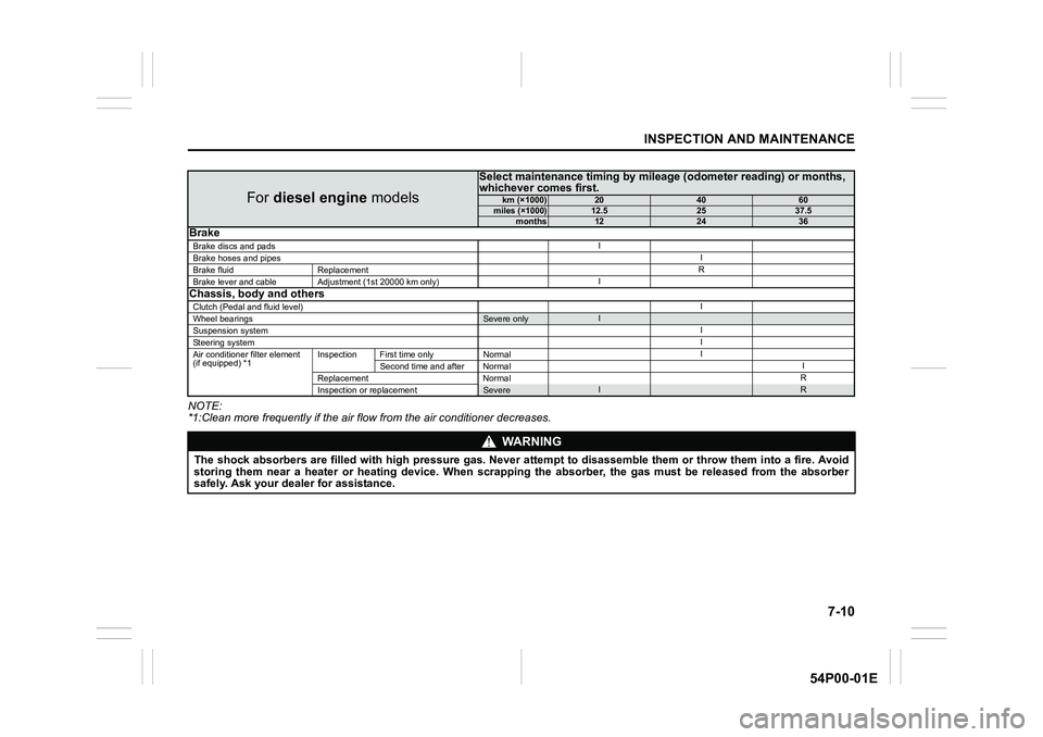
NOTE:
*1:Clean more frequently if the air flow from the air conditioner decreases.
For diesel engine models
Select maintenance timing by mileage (odometer reading) or months,
whichever comes first.
km (×1000)204060miles (×1000)12.52537.5months122436Brake
Brake discs and padsI
Brake hoses and pipesI
Brake fluid ReplacementR
Brake lever and cable Adjustment (1st 20000 km only)I
Chassis, body and others
Clutch (Pedal and fluid level)I
Wheel bearingsSevere onlyI
Suspension systemI
Steering systemI
Air conditioner filter element
(if equipped) *1Inspection First time only NormalI
Second time and after NormalI
Replacement NormalR
Inspection or replacement
SevereIR
WA R N I N G
The shock absorbers are filled with high pressure gas. Never attempt to disassemble them or throw them into a fire. Avoid
storing them near a heater or heating device. When scrapping the absorber, the gas must be released from the absorber
safely. Ask your dealer for assistance.
Page 353 of 482
7-15
INSPECTION AND MAINTENANCE
54P00-01E
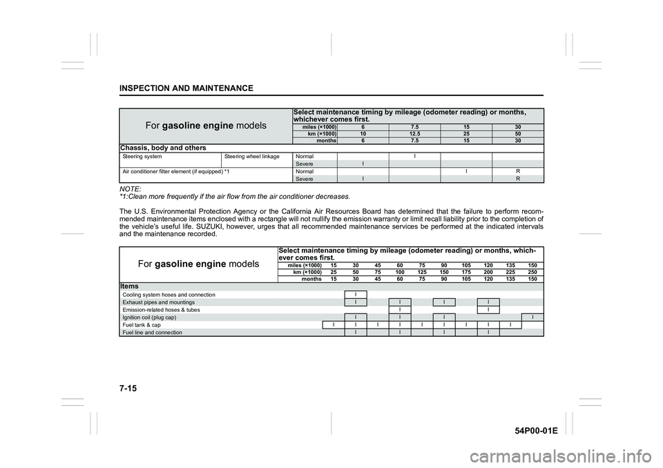
NOTE:
*1:Clean more frequently if the air flow from the air conditioner decreases.
The U.S. Environmental Protection Agency or the California Air Resources Board has determined that the failure to perform recom-
mended maintenance items enclosed with a rectangle will not nullify the emission warranty or limit recall liability prior to the completion of
the vehicle’s useful life. SUZUKI, however, urges that all recommended maintenance services be performed at the indicated intervals
and the maintenance recorded.
For gasoline engine models
Select maintenance timing by mileage (odometer reading) or months,
whichever comes first.
miles (×1000)67.51530km (×1000)1012.52550months67.51530Chassis, body and others
Steering system Steering wheel linkage NormalISevereI
Air conditioner filter element (if equipped) *1 NormalIRSevereIR
For gasoline engine models
Select maintenance timing by mileage (odometer reading) or months, which-
ever comes first.
miles (×1000)15 30 45 60 75 90 105 120 135 150
km (×1000) 25 50 75 100 125 150 175 200 225 250
months 15 30 45 60 75 90 105 120 135 150
Items
Cooling system hoses and connectionIExhaust pipes and mountingsIIII
Emission-related hoses & tubesIIIgnition coil (plug cap)IIII
Fuel tank & capIIIIIIIII
Fuel line and connectionIIII
Page 354 of 482
7-16
INSPECTION AND MAINTENANCE
54P00-01E
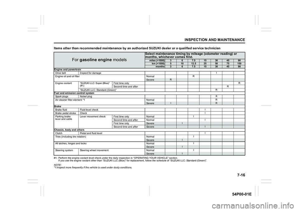
Items other than recommended maintenance by an authorized SUZUKI dealer or a qualified service technician
#1: Perform the engine coolant level check under the daily inspection in “OPERATING YOUR VEHICLE” section.
If you use the engine coolant other than “SUZUKI LLC (Blue)” for replacement, follow the schedule of “SUZUKI LLC: Standard (Green)”.
NOTE:
*1:Inspect more frequently if the vehicle is used under dusty conditions.
For gasoline engine models
Select maintenance timing by mileage (odometer reading) or
months, whichever comes first.
miles (×1000)367.515304590km (×1000)51012.5255075150months367.515304590
Engine and powertrain
Drive belt Inspect for damageI
Engine oil and oil filter NormalR
SevereR
Engine coolant“SUZUKI LLC: Super (Blue)”
(#1)First time onlyR
Second time and afterR
“SUZUKI LLC: Standard (Green)”R
Fuel and emission control system
Spark plugs Nickel plug
R
Air cleaner filter element *1 NormalRSevereIRBrake
Brake fluid Fluid level checkI
Brake pedal stroke CheckI
Parking brake
lever and cableLever movement check First time only NormalI
Second time and after NormalI
First time only
SevereI
Second time and afterSevereIChassis, body and others
Clutch Pedal and fluid levelI
Tires (including tire rotation) NormalI
SevereI
All latches, hinges and locks NormalISevereI
Steering system Steering wheel movement NormalISevereI
Page 356 of 482
7-18
INSPECTION AND MAINTENANCE
54P00-01E
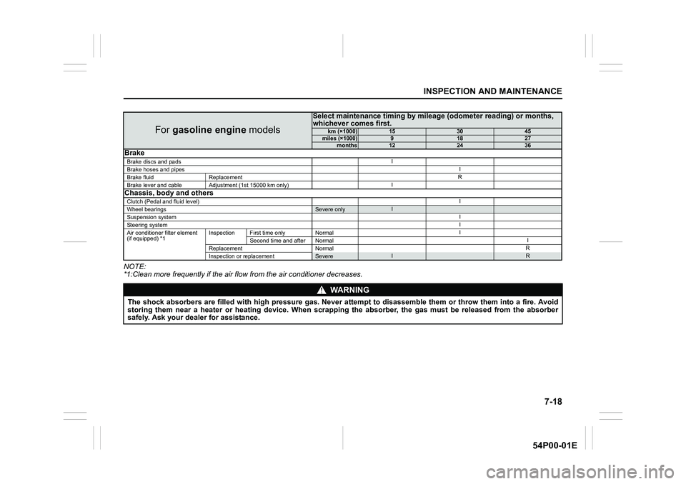
NOTE:
*1:Clean more frequently if the air flow from the air conditioner decreases.
For gasoline engine models
Select maintenance timing by mileage (odometer reading) or months,
whichever comes first.
km (×1000)153045miles (×1000)91827months122436Brake
Brake discs and padsI
Brake hoses and pipesI
Brake fluid ReplacementR
Brake lever and cable Adjustment (1st 15000 km only)I
Chassis, body and others
Clutch (Pedal and fluid level)I
Wheel bearingsSevere onlyI
Suspension systemI
Steering systemI
Air conditioner filter element
(if equipped) *1Inspection First time only NormalI
Second time and after NormalI
Replacement NormalR
Inspection or replacement
SevereIR
WA R N I N G
The shock absorbers are filled with high pressure gas. Never attempt to disassemble them or throw them into a fire. Avoid
storing them near a heater or heating device. When scrapping the absorber, the gas must be released from the absorber
safely. Ask your dealer for assistance.
Page 373 of 482
7-35
INSPECTION AND MAINTENANCE
54P00-01E
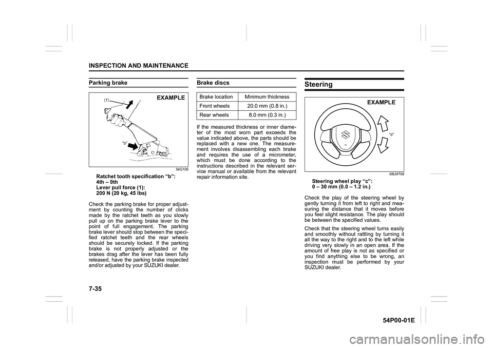
Parking brake
54G109
Ratchet tooth specification “b”:
4th – 9th
Lever pull force (1):
200 N (20 kg, 45 lbs)
Check the parking brake for proper adjust-
ment by counting the number of clicks
made by the ratchet teeth as you slowly
pull up on the parking brake lever to the
point of full engagement. The parking
brake lever should stop between the speci-
fied ratchet teeth and the rear wheels
should be securely locked. If the parking
brake is not properly adjusted or the
brakes drag after the lever has been fully
released, have the parking brake inspected
and/or adjusted by your SUZUKI dealer.
Brake discs
If the measured thickness or inner diame-
ter of the most worn part exceeds the
value indicated above, the parts should be
replaced with a new one. The measure-
ment involves disassembling each brake
and requires the use of a micrometer,
which must be done according to the
instructions described in the relevant ser-
vice manual or available from the relevant
repair information site.
Steering
68LM708
Steering wheel play “c”:
0 – 30 mm (0.0 – 1.2 in.)
Check the play of the steering wheel by
gently turning it from left to right and mea-
suring the distance that it moves before
you feel slight resistance. The play should
be between the specified values.
Check that the steering wheel turns easily
and smoothly without rattling by turning it
all the way to the right and to the left while
driving very slowly in an open area. If the
amount of free play is not as specified or
you find anything else to be wrong, an
inspection must be performed by your
SUZUKI dealer.
EXAMPLEBrake location Minimum thickness
Front wheels 20.0 mm (0.8 in.)
Rear wheels 8.0 mm (0.3 in.)
“c”
EXAMPLE
Page 375 of 482
7-37
INSPECTION AND MAINTENANCE
54P00-01E
54G136
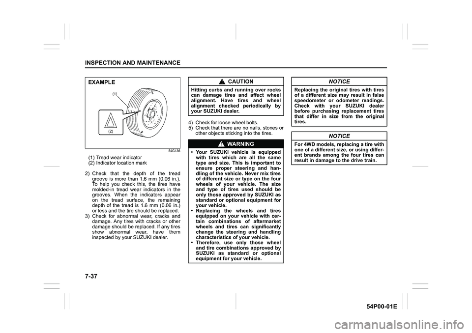
(1) Tread wear indicator
(2) Indicator location mark
2) Check that the depth of the tread
groove is more than 1.6 mm (0.06 in.).
To help you check this, the tires have
molded-in tread wear indicators in the
grooves. When the indicators appear
on the tread surface, the remaining
depth of the tread is 1.6 mm (0.06 in.)
or less and the tire should be replaced.
3) Check for abnormal wear, cracks and
damage. Any tires with cracks or other
damage should be replaced. If any tires
show abnormal wear, have them
inspected by your SUZUKI dealer.4) Check for loose wheel bolts.
5) Check that there are no nails, stones or
other objects sticking into the tires.
EXAMPLECAUTION
Hitting curbs and running over rocks
can damage tires and affect wheel
alignment. Have tires and wheel
alignment checked periodically by
your SUZUKI dealer.
WA R N I N G
• Your SUZUKI vehicle is equipped
with tires which are all the same
type and size. This is important to
ensure proper steering and han-
dling of the vehicle. Never mix tires
of different size or type on the four
wheels of your vehicle. The size
and type of tires used should be
only those approved by SUZUKI as
standard or optional equipment for
your vehicle.
• Replacing the wheels and tires
equipped on your vehicle with cer-
tain combinations of aftermarket
wheels and tires can significantly
change the steering and handling
characteristics of your vehicle.
• Therefore, use only those wheel
and tire combinations approved by
SUZUKI as standard or optional
equipment for your vehicle.
NOTICE
Replacing the original tires with tires
of a different size may result in false
speedometer or odometer readings.
Check with your SUZUKI dealer
before purchasing replacement tires
that differ in size from the original
tires.
NOTICE
For 4WD models, replacing a tire with
one of a different size, or using differ-
ent brands among the four tires can
result in damage to the drive train.