sensor SUZUKI IGNIS 2019 Owners Manual
[x] Cancel search | Manufacturer: SUZUKI, Model Year: 2019, Model line: IGNIS, Model: SUZUKI IGNIS 2019Pages: 505, PDF Size: 8.36 MB
Page 8 of 505
75RM4-01E
RECOMMENDATION OF GENUINE SUZUKI PARTS AND ACCESSORIES USESUZUKI strongly recommends the use of genuine SUZUKI parts* and accessories. Genuine SUZUKI parts and accessories are built to
the highest standards of quality and performance, and are desig ned to fit your vehicle’s exact specifications.
A wide variety of non-genuine replacement parts and accessories for SUZUKI vehicles are currently available in the market. Using these
parts and accessories can affect the vehicle performance and sh orten its useful life. Therefore, installation of non-genuine SUZUKI parts
and accessories is not covered under warranty.Non-genuine SUZUKI parts and accessoriesSome parts and accessories may be approved by certain authorities in your country.
Some parts and accessories are sold as SUZUKI-authorized replac ement parts and accessories. Some genuine SUZUKI parts and
accessories are sold as re-use parts and accessories. These par ts and accessories are non-genuine SUZUKI parts and accessories and
use of these parts is not covered under warranty.Re-use of genuine SUZUKI parts and accessoriesThe resale or re-use of the following items which could cause h azards for users is expressly forbidden:
• Air bag components and all other pyrotechn ic items, including their components (e.g. cushion , control devices and sensors)
• Seat belt system, inclu ding their components (e.g. webbing, buckles and retractors)
The air bag and seat belt pretensioner components contain explo sive chemicals. These components should be removed and disposed
of properly by SUZUKI-authorized service shop or scrap yard to avoid unintended explosion before scrapping.
*The parts remanufactured under SUZUKI’s approval can be used a s genuine SUZUKI parts in Europe.
Page 75 of 505
2-52
BEFORE DRIVING
75RM4-01E
Seat belt pretensioner system
63J269
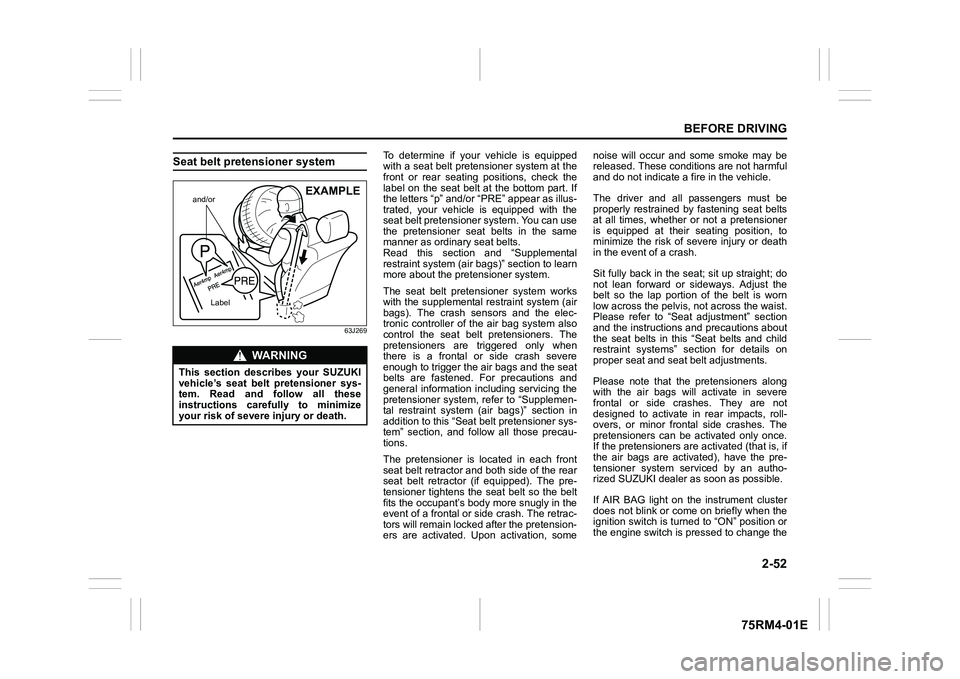
To determine if your vehicle is equipped
with a seat belt pretensioner system at the
front or rear seating positions, check the
label on the seat belt at the bottom part. If
the letters “p” and/or “PRE” appear as illus-
trated, your vehicle is equipped with the
seat belt pretensioner system. You can use
the pretensioner seat belts in the same
manner as ordinary seat belts.
Read this section and “Supplemental
restraint system (air bags)” section to learn
more about the pretensioner system.
The seat belt pretensioner system works
with the supplemental r estraint system (air
bags). The crash sensors and the elec-
tronic controller of t he air bag system also
control the seat belt pretensioners. The
pretensioners are triggered only when
there is a frontal or side crash severe
enough to trigger the air bags and the seat
belts are fastened. For precautions and
general information including servicing the
pretensioner system, refer to “Supplemen-
tal restraint system (air bags)” section in
addition to this “Seat belt pretensioner sys-
tem” section, and follow all those precau-
tions.
The pretensioner is located in each front
seat belt retractor and both side of the rear
seat belt retractor (if equipped). The pre-
tensioner tightens the seat belt so the belt
fits the occupant’s body more snugly in the
event of a frontal or side crash. The retrac-
tors will remain locked after the pretension-
ers are activated. Upon activation, some noise will occur and some smoke may be
released. These conditions are not harmful
and do not indicate a fire in the vehicle.
The driver and all passengers must be
properly restrained by fastening seat belts
at all times, whether or not a pretensioner
is equipped at their seating position, to
minimize the risk of severe injury or death
in the event o
f a crash.
Sit fully back in the seat; sit up straight; do
not lean forward or sideways. Adjust the
belt so the lap portion of the belt is worn
low across the pelvis , not across the waist.
Please refer to “Seat adjustment” section
and the instructions and precautions about
the seat belts in this “Seat belts and child
restraint systems” section for details on
proper seat and seat belt adjustments.
Please note that the pretensioners along
with the air bags will activate in severe
frontal or side crashes. They are not
designed to activate in rear impacts, roll-
overs, or minor frontal side crashes. The
pretensioners can be activated only once.
If the pretensioners are activated (that is, if
the air bags are activated), have the pre-
tensioner system serviced by an autho-
rized SUZUKI dealer as soon as possible.
If AIR BAG light on the instrument cluster
does not blink or come on briefly when the
ignition switch is turned to “ON” position or
the engine switch is pressed to change the
WA R N I N G
This section describes your SUZUKI
vehicle’s seat belt pretensioner sys-
tem. Read and follow all these
instructions carefully to minimize
your risk of severe injury or death.
and/or
Label
EXAMPLE
Page 77 of 505
2-54
BEFORE DRIVING
75RM4-01E
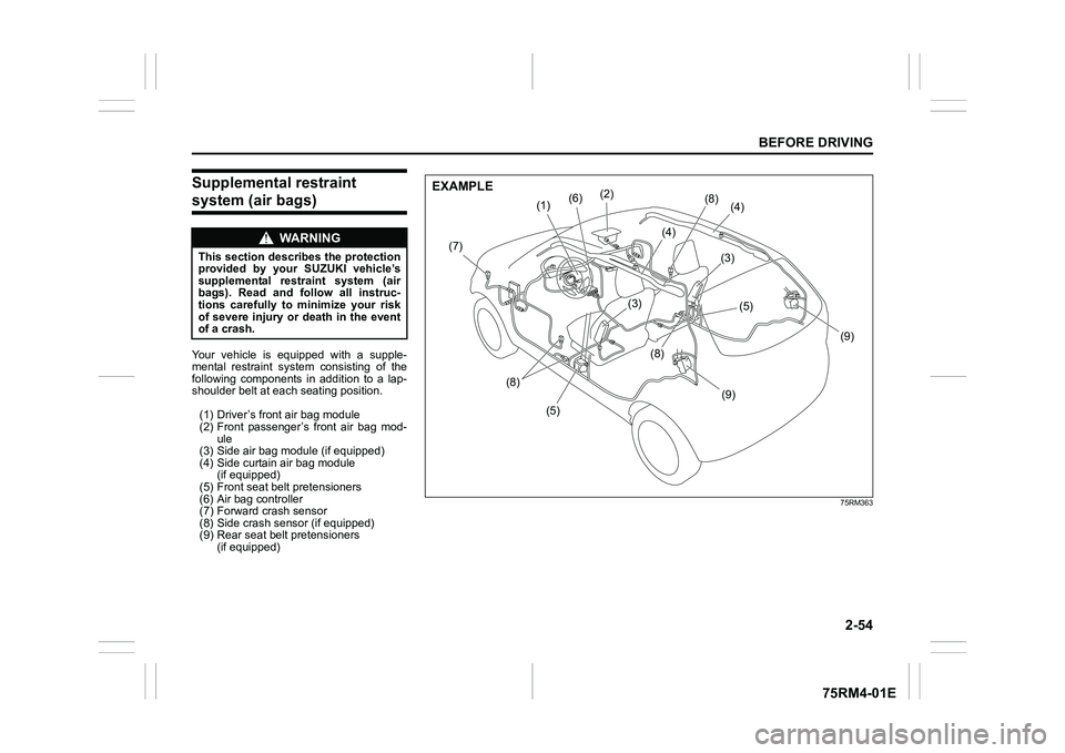
Supplemental restraint system (air bags) Your vehicle is equipped with a supple-
mental restraint system consisting of the
following components in addition to a lap-
shoulder belt at each seating position.
(1) Driver’s front air bag module
(2) Front passenger’s front air bag mod- ule
(3) Side air bag module (if equipped)
(4) Side curtain air bag module (if equipped)
(5) Front seat belt pretensioners
(6) Air bag controller
(7) Forward crash sensor
(8) Side crash sensor (if equipped)
(9) Rear seat belt pretensioners (if equipped)
WA R N I N G
This section describes the protection
provided by your SUZUKI vehicle’s
supplemental restraint system (air
bags). Read and follow all instruc-
tions carefully to minimize your risk
of severe injury or death in the event
of a crash.
75RM363
(5)
(8)
(7)
(6)
(1)
(2)
(4)
(9)
(9)
(8)
(5)
(3)
(3)
(4)
(8)
EXAMPLE
Page 86 of 505
2-63BEFORE DRIVING
75RM4-01E
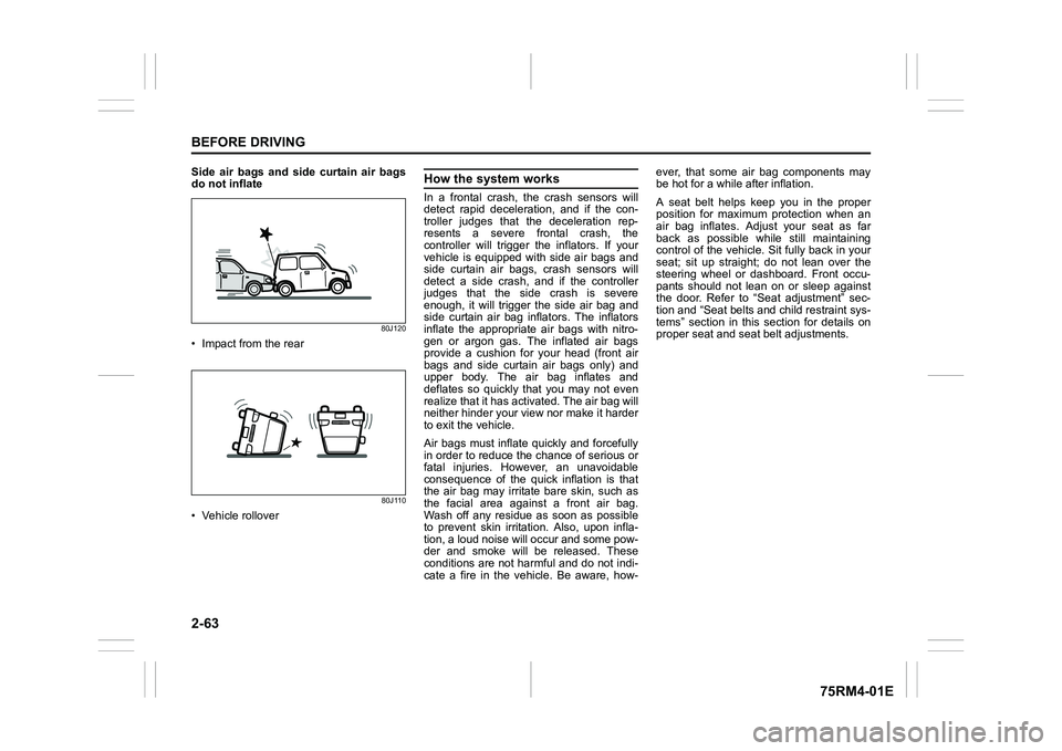
Side air bags and side curtain air bags
do not inflate
80J120
• Impact from the rear
80J110
• Vehicle rollover
How the system worksIn a frontal crash, the crash sensors will
detect rapid deceleration, and if the con-
troller judges that the deceleration rep-
resents a severe frontal crash, the
controller will trigger the inflators. If your
vehicle is equipped with side air bags and
side curtain air bags, crash sensors will
detect a side crash, and if the controller
judges that the side crash is severe
enough, it will trigger the side air bag and
side curtain air bag inflators. The inflators
inflate the appropriate air bags with nitro-
gen or argon gas. The inflated air bags
provide a cushion for your head (front air
bags and side curtain air bags only) and
upper body. The air bag inflates and
deflates so quickly that you may not even
realize that it has activated. The air bag will
neither hinder your view nor make it harder
to exit the vehicle.
Air bags must inflate quickly and forcefully
in order to reduce the chance of serious or
fatal injuries. However, an unavoidable
consequence of the quick inflation is that
the air bag may irritate bare skin, such as
the facial area against a front air bag.
Wash off any residue as soon as possible
to prevent skin irritation. Also, upon infla-
tion, a loud noise will occur and some pow-
der and smoke will be released. These
conditions are not harmful and do not indi-
cate a fire in the vehicle. Be aware, how-ever, that some air bag components may
be hot for a while after inflation.
A seat belt helps keep you in the proper
position for maximum protection when an
air bag inflates. Adjust your seat as far
back as possible while still maintaining
control of the vehicle. Sit fully back in your
seat; sit up straight; do not lean over the
steering wheel or dashboard. Front occu-
pants should not lean on or sleep against
the door. Refer to “Seat adjustment” sec-
tion and “Seat belts and child restraint sys-
tems” section in this
section for details on
proper seat and seat belt adjustments.
Page 88 of 505
2-65BEFORE DRIVING
75RM4-01E
Your vehicle is equipped with a diagnostic
module which records information about
the air bag system if the air bags deploy in
a crash. The module records information
about overall system status, and which
sensors activated the deployment.
Servicing the air bag system
If the air bags inflate, have the air bags
and related components replaced by an
authorized SUZUKI dealer as soon as pos-
sible.
If your vehicle ever gets in deep water and
the driver’s floor is submerged, the air bag
controller could be damaged. If this hap-
pens, ask your SUZUKI dealer to check
the air bag system as soon as possible.
Special procedures are required for servic-
ing or replacing an air bag. For that rea-
son, only an authorized SUZUKI dealer
should be allowed to service or replace
your air bags. Remind anyone who ser-
vices your SUZUKI vehicle that it has air
bags.
Service on or around air bag components
or wiring must be performed only by an
authorized SUZUKI dealer. Improper ser-
vice could result in unintended air bag
deployment or could render the air bag
inoperative. Either of these two conditions
may result in severe injury. To prevent damage or unintended inflation
of the air bag system, check that the lead-
acid battery is disconnected and the igni-
tion switch has been in “LOCK” position or
the ignition mode has been LOCK (OFF)
for at least 90 seconds before performing
any electrical service work on your
SUZUKI vehicle. Do not touch air bag sys-
tem components or wires. The wires are
wrapped with yellow tape or yellow tubing,
and the couplers are yellow for easy identi-
fication.
Scrapping a vehicle that has an uninflated
air bag can be hazardous. Ask your dealer,
body repair shop or scrap yard for help
with disposal.
Front passenger air bag deactiva-tion system (if equipped)
75RM189
The front passenger’s front air bag must
be deactivated if a child restraint system is
to be installed on the front passenger’s
seat.
When the ignition switch is turned to “ON”
position or the engine switch is pressed to
change the ignition mode to ON, “PAS-
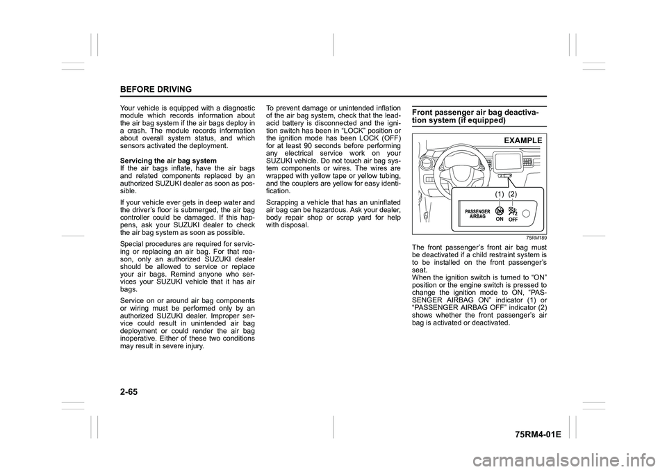
SENGER AIRBAG ON” indicator (1) or
“PASSENGER AIRBAG OFF” indicator (2)
shows whether the front passenger’s air
bag is activated or deactivated.
(1)
(2)EXAMPLE
Page 140 of 505
2-117BEFORE DRIVING
75RM4-01E
68PM00230
With the headlights on, push the lever for-
ward to switch to the high beams (main
beams) or pull the lever toward you to
switch to the low beams. When the high
beams (main beams) are on, a light on the
instrument cluster will come on. To
momentarily activate the high beams (main
beams) as a passing signal, pull the lever
slightly toward you and release it when you
have completed the signal.
Auto-on headlight system (if equipped)
75RM110
The Auto-on headlig ht system automati-
cally turns on all lights that are operated by
the lighting control lever on the steering
column, when the following four conditions
are all met.
Conditions for Auto-on headlight system
operation:
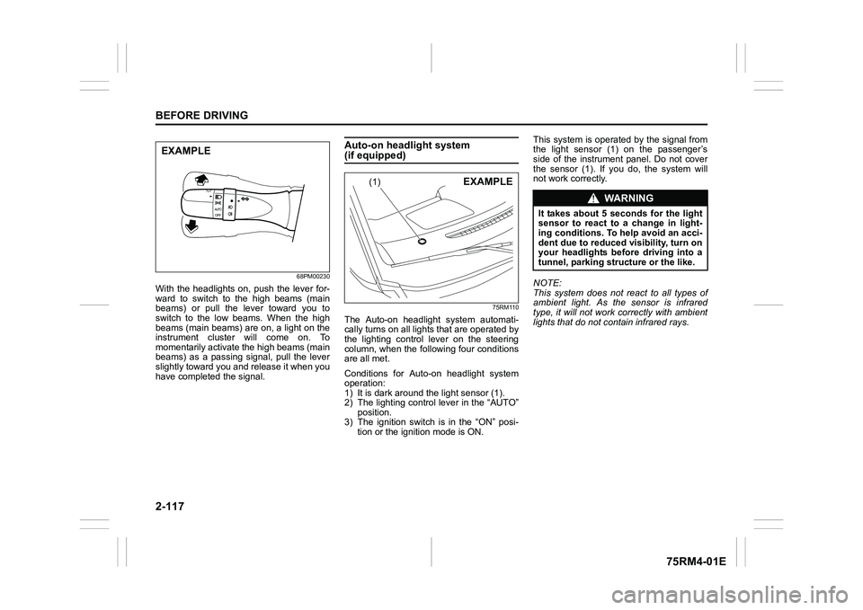
1) It is dark around the light sensor (1).
2) The lighting control lever in the “AUTO” position.
3) The ignition switch is in the “ON” posi-
tion or the ignition mode is ON. This system is operated by the signal from
the light sensor (1) on the passenger’s
side of the instrument panel. Do not cover
the sensor (1). If you do, the system will
not work correctly.
NOTE:
This system does not react to all types of
ambient light. As the sensor is infrared
type, it will not work correctly with ambient
lights that do not contain infrared rays.
EXAMPLE
(1)
EXAMPLE
WA R N I N G
It takes about 5 seconds for the light
sensor to react to a change in light-
ing conditions. To help avoid an acci-
dent due to reduced visibility, turn on
your headlights before driving into a
tunnel, parking structure or the like.
Page 219 of 505
3-66
OPERATING YOUR VEHICLE
75RM4-01E
Temporary stop of the stereo camera
Under the following situations, the function
of the stereo camera stops temporarily.
When the situations are improved, the
temporary stop of the function will be can-
celed.
• When the visibility of the stereo camerais poor
• When the temperature of the body of
stereo camera i s low or high
• When the systems related the dual cam- era brake support stops temporarily
• When the lead-acid battery has a volt- age abnormality
• When the automatic adjustment of the
stereo camera is insufficient
Failure of the stereo camera
When the stereo camera is failure, the
function of the stereo camera stops until
the ignition switch is turned to “LOCK”
position or the engine switch is pressed to
change the ignition mode to LOCK (OFF).
Find a safe place to park and turn the igni-
tion switch to “LOCK” position or change
the ignition mode to LOCK (OFF) by press-
ing the engine switch.
Restart the engine, and check that the dual
camera brake support indicator light and
lane departure warning indicator light go
off.
• If both of the indicators stay on after restarting the engine, there may be a
failure of the stereo camera. Ask your
SUZUKI dealer to have the stereo cam-
era inspected. It is thought that the cause of failure is the
followings.
• When the stereo camera has an abnor-
mality
• When the temperature of the body of stereo camera is t oo low or too high
• When the mounting position of the ste- reo camera is shifted greatly
• When there are communication abnor-
malities among the engine, transaxle
and brake controller
• When the dual camera brake support
OFF switch has an abnormality
• When the steering angle sensor has an abnormality
• When the power supply of the stereo camera is cut
NOTE:
• Under the following situations, the dual camera brake support indicator light and
lane departure warning indicator light
come on after the engine has started, it
does not indicate a malfunction. Once
the ignition switch is turned to “LOCK”
position or the engine switch is pressed
to change the ignition mode to LOCK
(OFF) and then the engine is restarted,
these indicators will go off.
– When the automatic brake system hasbeen operating 3 times
– When the automatic brake system has
been operating for long periods • The function of the stereo camera stops
if the dual camera brake support indica-
tor light and lane departure warning indi-
cator light come on and there may be a
failure of the stereo camera, but it does
not hinder normal driving.
Pedestrian detection
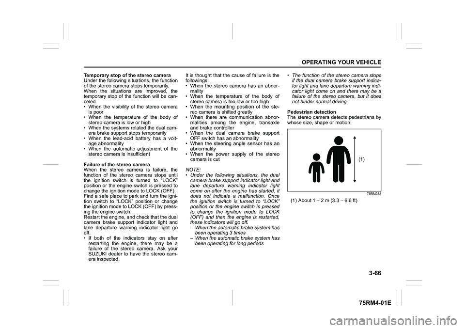
The stereo camera detects pedestrians by
whose size, shape or motion.
75RM238
(1) About 1 – 2 m (3.3 – 6.6 ft)
(1)
Page 238 of 505
3-85OPERATING YOUR VEHICLE
75RM4-01E
On models equipped with the ENG A-
STOP system, the hill hold control system
is activated when the engine is restarted
after being stopped automatically, even if
the previous conditions are not met.
NOTE:
When the hill hold control system is acti-
vated, you may hear a sound coming from
the engine, or you may feel hardness of
the brake pedal. These are normal and do
not indicate a malfunction.
75RM224
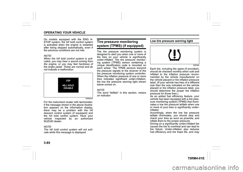
For the instrument cluster with tachometer,
if the message shown in the above illustra-
tion appears on the information display,
there may be a problem with the hill
descent control system (if equipped) and
the hill hold control system. Have your
vehicle inspected by an authorized
SUZUKI dealer.
NOTE:
The hill hold control system will not acti-
vate while this message is displayed.
Tire pressure monitoring system (TPMS) (if equipped)The tire pressure monitoring system is
designed to alert you when one or more of
the tires on your vehicle is significantly
under-inflated. The tire pressure monitor-
ing system (TPMS) sensor containing a
unique identification code is mounted on
each wheel. The TPMS sensors transmit
tire pressure signals to the receiver of the
tire pressure monitoring system controller.
When the inflation pressure of one or more
tires indicates signif icant under-inflation,
the low tire pressure warning light shown
below comes on.
NOTE:
The word “telltale” in this section, means
an indicator.
Low tire pressure warning light
52D305
Each tire, including the spare (if provided),
should be checked monthly when cold and
inflated to the inflation pressure recom-
mended by the vehicle manufacturer on
the vehicle placard or tire inflation pressure
label. (If your vehicle has tires of a different
size than the size indicated on the vehicle
placard or tire inflation pressure label, you
should determine the proper tire inflation
pressure for those tires.)
As an added fuel efficiency feature, your
vehicle has been equipped with a tire pres-
sure monitoring system (TPMS) that illumi-
nates a low tire pressure telltale when one
or more of your tires is significantly under-
inflated.
Accordingly, when the low tire pressure
telltale illuminates, you should stop and
check your tires as soon as possible, and
inflate them to the proper pressure.
Driving on a significantly under-inflated tire
causes the tire to overheat and can lead to
tire failure. Under-inf lation also reduces
fuel efficiency and tire tread life, and may
Page 242 of 505
3-89OPERATING YOUR VEHICLE
75RM4-01E
61MM0A199
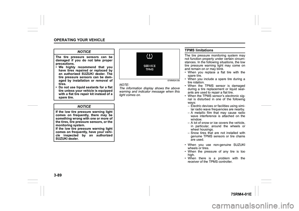
NOTE:
The information display shows the above
warning and indicator message when this
light comes on.
TPMS limitationsThe tire pressure monitoring system may
not function properly under certain circum-
stances. In the following situations, the low
tire pressure warning light may come on
and remain on or may blink.
• When you replace a flat tire with thespare tire.
• When you include a spare tire during a
tire rotation.
• When the TPMS sensor is damaged during a tire replacement or liquid seal-
ants are used to r epair a flat tire.
• When the TPMS sensor’s electronic sig- nal is disturbed in one of the following
ways:
– Electric devices or fa cilities using simi-
lar radio wave frequencies are nearby.
– A metallic film that may cause radio wave interference is attached on the
window.
– A lot of snow or ice covers the vehicle, in particular, around the wheels or
wheel housings.
– Snow tires that are not installed with genuine TPMS sensors or tire chains
are used.
• When you use non-genuine SUZUKI wheels or tires.
• When the pressure of any tire is too high.
• When there is a problem with the
receiver of the TPMS controller.
NOTICE
The tire pressure sensors can be
damaged if you do not take proper
precautions.
• We highly recommend that youhave tires repaired or replaced by
an authorized SUZUKI dealer. The
tire pressure sensors can be dam-
aged by installation or removal of
tires.
• Do not use liquid sealants for a flat tire unless your vehicle is equipped
with a flat tire repair kit instead of a
spare tire.
NOTICE
If the low tire pressure warning light
comes on frequently, there may be
something wrong with one or more of
the tires, tire pressure sensors, or the
monitoring system.
If the low tire pressure warning light
comes on frequently, have your vehi-
cle inspected by an authorized
SUZUKI dealer.
Page 246 of 505
3-93OPERATING YOUR VEHICLE
75RM4-01E
75RM335
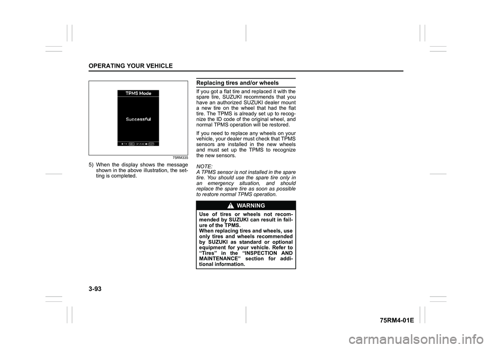
5) When the display shows the messageshown in the above illustration, the set-
ting is completed.
Replacing tires and/or wheelsIf you got a flat tire and replaced it with the
spare tire, SUZUKI recommends that you
have an authorized SUZUKI dealer mount
a new tire on the wheel that had the flat
tire. The TPMS is already set up to recog-
nize the ID code of the original wheel, and
normal TPMS operati on will be restored.
If you need to replace any wheels on your
vehicle, your dealer must check that TPMS
sensors are installed in the new wheels
and must set up the TPMS to recognize
the new sensors.
NOTE:
A TPMS sensor is not installed in the spare
tire. You should use the spare tire only in
an emergency situation, and should
replace the spare tire as soon as possible
to restore normal TPMS operation.
WA R N I N G
Use of tires or wheels not recom-
mended by SUZUKI can result in fail-
ure of the TPMS.
When replacing tires and wheels, use
only tires and wheels recommended
by SUZUKI as standard or optional
equipment for your vehicle. Refer to
“Tires” in the “INSPECTION AND
MAINTENANCE” section for addi-
tional information.