height SUZUKI IGNIS 2019 Owners Manual
[x] Cancel search | Manufacturer: SUZUKI, Model Year: 2019, Model line: IGNIS, Model: SUZUKI IGNIS 2019Pages: 505, PDF Size: 8.36 MB
Page 50 of 505
2-27BEFORE DRIVING
75RM4-01E
Front seatsSeat adjustment
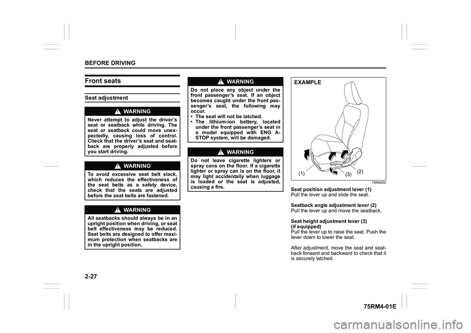
75RM302
Seat position adjustment lever (1)
Pull the lever up and slide the seat.
Seatback angle adju stment lever (2)
Pull the lever up and move the seatback.
Seat height adjustment lever (3)
(if equipped)
Pull the lever up to raise the seat. Push the
lever down to lower the seat.
After adjustment, move the seat and seat-
back forward and backward to check that it
is securely latched.
WA R N I N G
Never attempt to adjust the driver’s
seat or seatback while driving. The
seat or seatback could move unex-
pectedly, causing loss of control.
Check that the driver’s seat and seat-
back are properly adjusted before
you start driving.
WA R N I N G
To avoid excessive seat belt slack,
which reduces the effectiveness of
the seat belts as a safety device,
check that the seats are adjusted
before the seat belts are fastened.
WA R N I N G
All seatbacks should always be in an
upright position when driving, or seat
belt effectiveness may be reduced.
Seat belts are designed to offer maxi-
mum protection when seatbacks are
in the upright position.
WA R N I N G
Do not place any object under the
front passenger’s seat. If an object
becomes caught under the front pas-
senger’s seat, the following may
occur.
• The seat will not be latched.
• The lithium-ion battery, located under the front passenger’s seat in
a model equipped with ENG A-
STOP system, will be damaged.
WA R N I N G
Do not leave cigarette lighters or
spray cans on the floor. If a cigarette
lighter or spray can is on the floor, it
may light accidentally when luggage
is loaded or the seat is adjusted,
causing a fire.
(1) (2)
(3)EXAMPLE
Page 53 of 505
2-30
BEFORE DRIVING
75RM4-01E
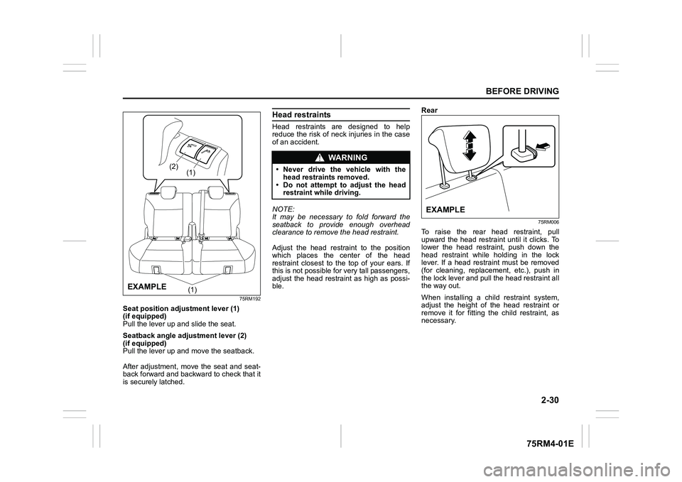
75RM192
Seat position adjustment lever (1)
(if equipped)
Pull the lever up and slide the seat.
Seatback angle adju stment lever (2)
(if equipped)
Pull the lever up and move the seatback.
After adjustment, move the seat and seat-
back forward and backward to check that it
is securely latched.
Head restraintsHead restraints are designed to help
reduce the risk of neck injuries in the case
of an accident.
NOTE:
It may be necessary to fold forward the
seatback to provide enough overhead
clearance to remove the head restraint.
Adjust the head restraint to the position
which places the center of the head
restraint closest to the top of your ears. If
this is not possible for very tall passengers,
adjust the head restraint as high as possi-
ble. Rear
75RM006
To raise the rear head restraint, pull
upward the head restraint until it clicks. To
lower the head restraint, push down the
head restraint while holding in the lock
lever. If a head restraint must be removed
(for cleaning, replacement, etc.), push in
the lock lever and pull the head restraint all
the way out.
When installing a chil
d restraint system,
adjust the height of the head restraint or
remove it for fitting the child restraint, as
necessary.
(1)
(2)
(1)
EXAMPLE
WA R N I N G
• Never drive the vehicle with the
head restraints removed.
• Do not attempt to adjust the head restraint while driving.
EXAMPLE
Page 62 of 505
2-39BEFORE DRIVING
75RM4-01E
• If a seat belt is unfastened when thevehicle speed is more than 15 km/h, the
corresponding light will come on and a
buzzer will sound.
The reminder will be automatically can-
celed when the rear seat belt is buckled or
the ignition switch is turned off, or the
engine switch is pressed to change the
ignition mode to LOCK (OFF).
Shoulder anchor height adjuster (if equipped)
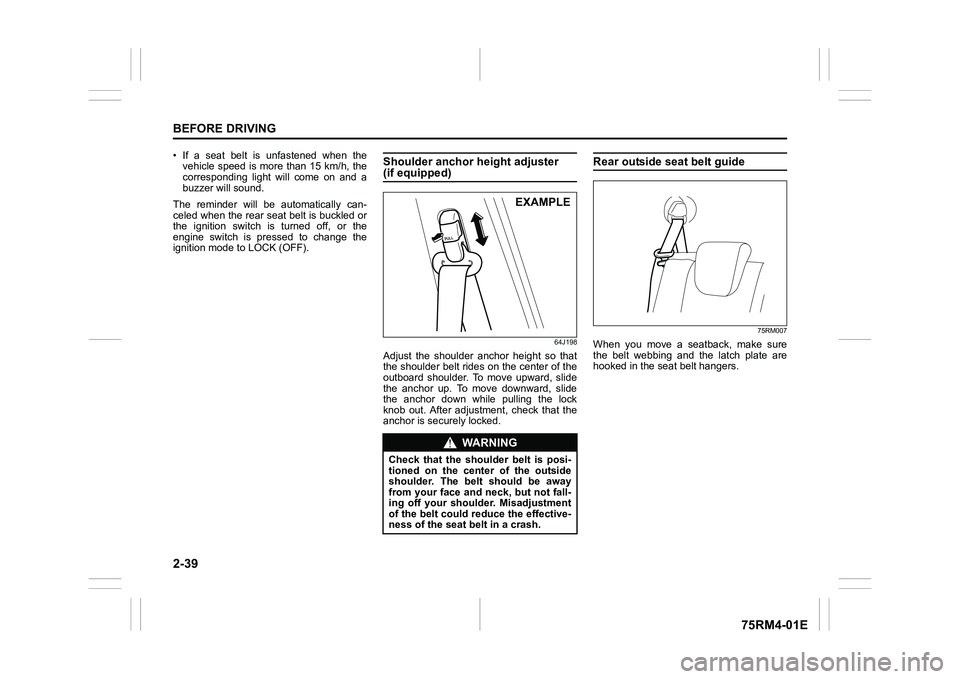
64J198
Adjust the shoulder anchor height so that
the shoulder belt rides on the center of the
outboard shoulder. To move upward, slide
the anchor up. To move downward, slide
the anchor down while pulling the lock
knob out. After adjustment, check that the
anchor is securely locked.
Rear outside seat belt guide
75RM007
When you move a seatback, make sure
the belt webbing and the latch plate are
hooked in the seat belt hangers.
WA R N I N G
Check that the shoulder belt is posi-
tioned on the cent er of the outside
shoulder. The belt should be away
from your face and neck, but not fall-
ing off your shoulder. Misadjustment
of the belt could reduce the effective-
ness of the seat belt in a crash.
EXAMPLE
Page 66 of 505
2-43BEFORE DRIVING
75RM4-01E
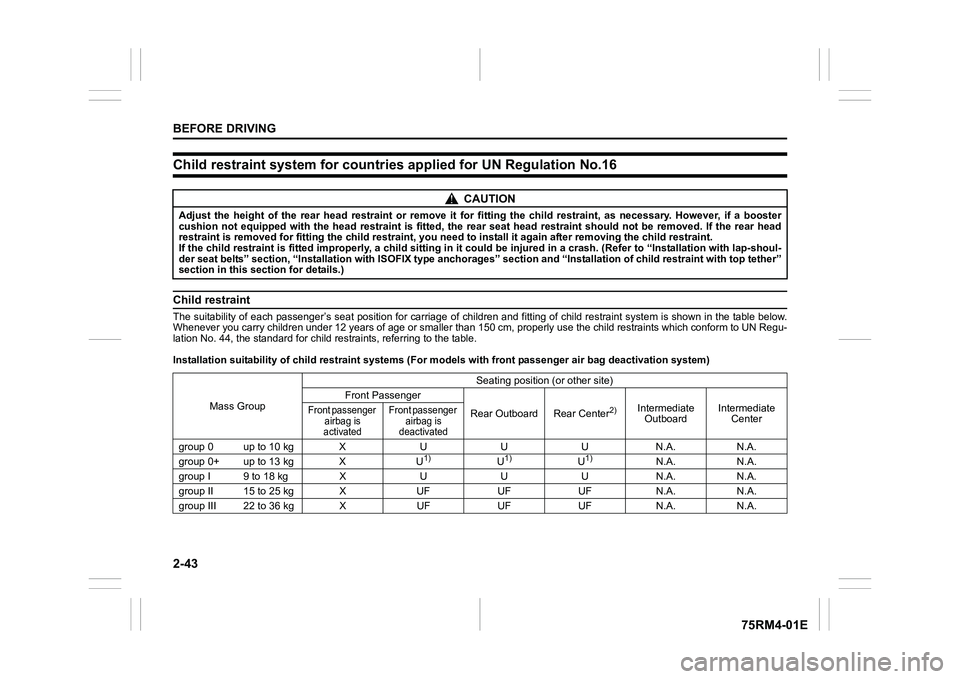
Child restraint system for countries applied for UN Regulation No.16Child restraintThe suitability of each passenger’s seat position for carriage of children and fitting of child restraint system is shown in t he table below.
Whenever you carry children under 12 years of age or smaller th an 150 cm, properly use the child restraints which conform to UN Regu-
lation No. 44, the standard for child restraints, referring to the table.
Installation suitability of chi ld restraint systems (For models with front passenger air bag deactivation system)
CAUTION
Adjust the height of the rear head restraint or remove it for f itting the child restraint, as necessary. However, if a booster
cushion not equipped with the head restraint is fitted, the rea r seat head restraint should not be removed. If the rear head
restraint is removed for fitting the child restraint, you need to install it again after removing the child restraint.
If the child restraint is fitted improperly, a child sitting in it could be injured in a crash. (Refer to “Installation with l ap-shoul-
der seat belts” section, “Instal lation with ISOFIX type anchora ges” section and “Installation of child restraint with top teth er”
section in this sect ion for details.)
Mass Group Seating position (or other site)
Front Passenger
Rear Outboard Rear Center
2)
Intermediate Outboard Intermediate
Center
Front passenger
airbag is
activated Front passenger
airbag is
deactivated
group 0 up to 10 kg X U U U N.A. N.A.
group 0+ up to 13 kg X U
1)
U1)
U1)
N.A. N.A.
group I 9 to 18 kg X U U U N.A. N.A.
group II 15 to 25 kg X UF UF UF N.A. N.A.
group III 22 to 36 kg X UF UF UF N.A. N.A.
Page 71 of 505
2-48
BEFORE DRIVING
75RM4-01E
Installation with lap-shoulder seat beltsNOTE:
Stow the removed head restraint in the lug-
gage compartment so it will not cause
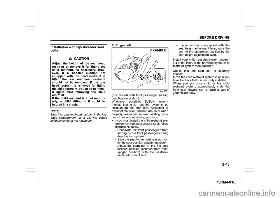
inconvenience to the occupants.ELR type belt
80JC021
(For models with front passenger air bag
deactivation system)
Whenever possible, SUZUKI recom-
mends that child restraint systems be
installed on the rear seat. According to
accident statistics, children are safer when
properly restrained in rear seating posi-
tions than in front seating positions.
• If you must install the child restraint sys-
tem on the front passe nger’s seat, follow
instructions below.
– Deactivate the front passenger’s front air bag by the front passenger air bag
deactivation system.
– Slide the seat to t he most rear position
by the seat position adjustment lever.
– Adjust the seatba ck at the 5th step
inclined position (counted from most
upright position) w ith the seatback
angle adjustment lever. – If your vehicle is equipped with the
seat height adjustment lever, raise the
seat to the uppermost position by the
seat height adjustment lever.
Install your child restraint system accord-
ing to the instructions provided by the child
restraint system manufacturer.
Check that the seat belt is securely
latched.
Move the child restraint system in all direc-
tions to check that it is securely installed.
When you put your child in the child
restraint system, appr opriately slide the
front seat forward not to touch a part of
your child’s body.
CAUTION
Adjust the height of the rear head
restraint or remove it for fitting the
child restraint, as necessary. How-
ever, if a booster cushion not
equipped with the head restraint is
fitted, the rear seat head restraint
should not be removed. If the rear
head restraint is removed for fitting
the child restraint, you need to install
it again after removing the child
restraint.
If the child restraint is fitted improp-
erly, a child sitting in it could be
injured in a crash.
EXAMPLE
Page 72 of 505
2-49BEFORE DRIVING
75RM4-01E
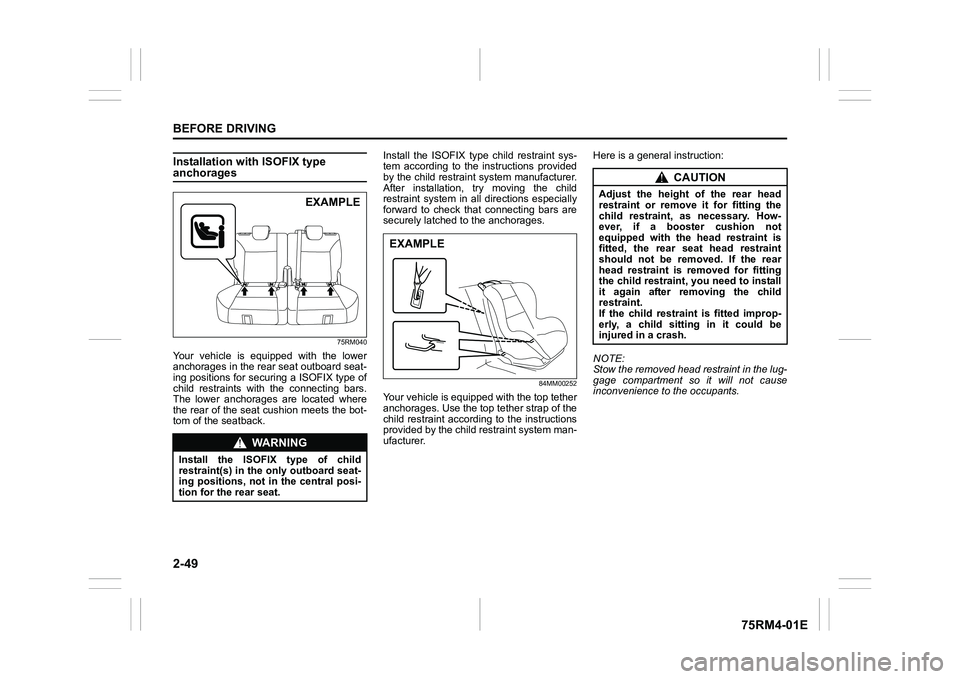
Installation with ISOFIX type anchorages
75RM040
Your vehicle is equipped with the lower
anchorages in the rear seat outboard seat-
ing positions for securing a ISOFIX type of
child restraints with the connecting bars.
The lower anchorages are located where
the rear of the seat cushion meets the bot-
tom of the seatback.Install the ISOFIX type child restraint sys-
tem according to the instructions provided
by the child restraint system manufacturer.
After installation, try moving the child
restraint system in all
directions especially
forward to check that connecting bars are
securely latched t o the anchorages.
84MM00252
Your vehicle is equipped with the top tether
anchorages. Use the top tether strap of the
child restraint according to the instructions
provided by the child restraint system man-
ufacturer. Here is a genera
l instruction:
NOTE:
Stow the removed head restraint in the lug-
gage compartment so it will not cause
inconvenience to the occupants.
WA R N I N G
Install the ISOFIX type of child
restraint(s) in the o nly outboard seat-
ing positions, not in the central posi-
tion for the rear seat.
EXAMPLE
EXAMPLE
CAUTION
Adjust the height of the rear head
restraint or remove it for fitting the
child restraint, as necessary. How-
ever, if a booster cushion not
equipped with the head restraint is
fitted, the rear seat head restraint
should not be removed. If the rear
head restraint is removed for fitting
the child restraint, you need to install
it again after removing the child
restraint.
If the child restraint is fitted improp-
erly, a child sitting in it could be
injured in a crash.
Page 151 of 505

2-128
BEFORE DRIVING
75RM4-01E
Tilt steering lock lever
75RM044
(1) LOCK
(2) UNLOCK
The lock lever is located under the steering
column. To adjust the steering wheel
height:
1) Push down the lock lever to unlock the
steering column.
2) Adjust the steering wheel to the desired height and lock the steering column by
pulling up the lock lever.
3) Try moving the steering wheel up and down to check that it is securely locked
in position.
Horn
75RM045
Press the horn button of the steering wheel
to sound the horn. The horn will sound with
the ignition switch in any position or any
ignition mode.
(1)
(2)
EXAMPLE
WA R N I N G
Never attempt to adjust the steering
wheel while the vehicle is moving or
you could lose contr ol of the vehicle.
EXAMPLE
Page 221 of 505
3-68
OPERATING YOUR VEHICLE
75RM4-01E
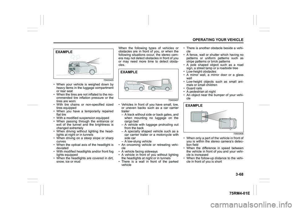
72M20405
• When your vehicle is weighed down byheavy items in the luggage compartment
or rear seat
• When the tires are not inflated to the rec- ommended tire inflation pressure or the
tires are worn
• With tire chains or non-specified sized
tires equipped
• When you have a temporarily repaired flat tire
• With a modified suspension equipped
• When passing through the entrance or exit of the tunnel and the brightness is
changed extremely
• When driving without lighting the head- lights at night or in tunnels
• When driving on a steep slope or sharp curves
• When the optical axis of the headlight is
deviated
• With modified headlights and/or front fog lights equipped
• When the headlights are covered in dirt, snow, ice or mud When the following types of vehicles or
obstacles are in front of you, or when the
following situations occur, the stereo cam-
era may not detect obstacles in front of you
or may need more time to detect obsta-
cles.
72M20407
• Vehicles in front of you have small, low,
or uneven backs such as a car carrier
trailer
– A track without side or back gates, andwhen mounting no luggage on the
cargo bed
– A vehicle with luggage protruding out
from the back
– A specially shaped vehicle such as a car carrier trailer or a motorcycle with
side car
– A low-slung vehicle
• An oncoming vehicle or retreating vehi-
cle
• A vehicle facing sideways
• A vehicle in front of you without lighting
the headlights at n ight or in tunnels
• There is a wall in front of the parked vehicle • There is another obstacle beside a vehi-
cle
• A fence, wall or shutter which having no
patterns or uniform patterns such as
stripe patterns or brick patterns
• A pole shaped object such as a road
sign, a street lamp or a roadside tree
• Low-height obstacles
• A mirror wall, a mirror door or a glass
wall
• Low-height objects such as small ani- mals or small children
• Guard rails
• A pedestrian at night
• An object near the bumper of your vehi- cle
72M20406
• When only a part of the vehicle in front ofyou is within the stereo camera’s detec-
tion field
• When the difference in speed between the vehicle in front of you and your vehi-
cle is increased
• When the follow-up distance to the vehi- cle in front of you is short
EXAMPLE
EXAMPLE
EXAMPLE
Page 344 of 505
6-3VEHICLE LOADING AND TOWING
75RM4-01E
TiresMirrorsCheck if your vehicle’s mirrors meet local
requirements for mirrors used on towing
vehicles. If they do not, you must install the
required mirrors before you tow.Vehicle/trailer loadingTo load your vehicle and trailer properly,
you must know how to measure gross
trailer weight and trailer nose weight.
Gross trailer weight is the weight of the
trailer plus all the cargo in it. You can mea-
sure gross trailer weight by putting the fully
loaded trailer on a vehicle scale.
Nose weight is the downward force
exerted on the tow bar by the trailer cou- pler, with the trailer fully loaded and the
coupler at its normal towing height. This
weight can be measured using a bathroom
scale.
The weight of your loaded trailer (gross
trailer weight) should never exceed towing
capacity.
Distribute cargo in your trailer so that nose
weight is about 10% of gross trailer weight,
but does not exceed “Maximum vertical
load” of 50 kg (110 lbs), and does not fall
below 25 kg (55 lbs) or 4%, whichever is
heavier, on trailer hitch point. You should
measure gross trailer weight and nose
weight before towing to check that your
load is properly distributed.
NOTE:
For 4WD model in Europe, in the Member
States where the road traffic legislation
allows it, as it is also stated in COMMIS-
SION REGULATION (EU) 1230/2012, the
technically permissi
ble maximum laden
mass (GVWR) of the vehicle may be
exceeded by not more than 40 kg (88 lbs)
in case of towing a trailer.
WA R N I N G
When towing a trailer, it is very
important for your vehicle and trailer
to have properly inflated tires. Your
vehicle’s tires should be inflated to
the pressures listed on your vehicles
tire information label. If laden pres-
sures are listed on the label, the tires
should be inflated to the laden pres-
sures. Inflate trailer tires according to
the specifications provided by the
trailer manufacturer.
WA R N I N G
Improper weight distribution of your
trailer may result in poor vehicle han-
dling and swaying of the trailer.
Always check that trailer nose weight
is about 10% of gross trailer weight,
but does not exceed “Maximum verti-
cal load” of 50 kg (110 lbs), and does
not fall below 25 kg (55 lbs) or 4%,
whichever is heavier, on trailer hitch
point. Also check that the cargo is
properly secured. Failure to observe
this requirement may result in an
accident.
WA R N I N G
Never overload cargo on your trailer
or your vehicle. Gross trailer weight
must never exceed towing capacity.
Gross vehicle weight (sum of the
weights of the vehicle, all the occu-
pants, accessories including tow
bars and a trailer hitch, cargo and
trailer nose weight) must never
exceed the Gross Vehicle Weight Rat-
ing (GVWR) listed in the “SPECIFICA-
TIONS” section.
Page 386 of 505
7-37INSPECTION AND MAINTENANCE
75RM4-01E
NOTE:
• The fluid level can be expected to gradu-ally fall as the brake pad and/or shoe
wear.
• Brake fluid absorbs water over time and
brake fluid with high water content may
cause vapor lock or brake system mal-
function.
Replace your brake fluid in accordance
with the maintenance schedule in your
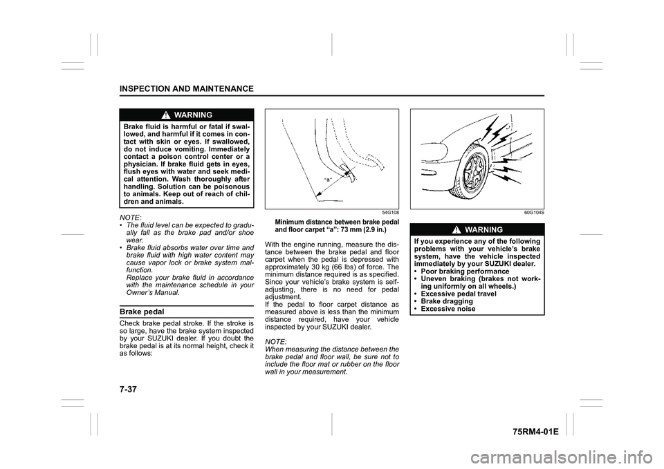
Owner’s Manual.Brake pedalCheck brake pedal stroke. If the stroke is
so large, have the brake system inspected
by your SUZUKI dealer. If you doubt the
brake pedal is at its normal height, check it
as follows:
54G108
Minimum distance between brake pedal
and floor carpet “a”: 73 mm (2.9 in.)
With the engine running, measure the dis-
tance between the brake pedal and floor
carpet when the pedal is depressed with
approximately 30 kg (66 lbs) of force. The
minimum distance required is as specified.
Since your vehicle’s brake system is self-
adjusting, there is no need for pedal
adjustment.
If the pedal to floor carpet distance as
measured above is less than the minimum
distance required, have your vehicle
inspected by your SUZUKI dealer.
NOTE:
When measuring the distance between the
brake pedal and floor wall, be sure not to
include the floor mat or rubber on the floor
wall in your measurement.
60G104S
WA R N I N G
Brake fluid is harmful or fatal if swal-
lowed, and harmful if it comes in con-
tact with skin or eyes. If swallowed,
do not induce vomiting. Immediately
contact a poison control center or a
physician. If brake fluid gets in eyes,
flush eyes with water and seek medi-
cal attention. Wash thoroughly after
handling. Solution can be poisonous
to animals. Keep out of reach of chil-
dren and animals.
WA R N I N G
If you experience any of the following
problems with your vehicle’s brake
system, have the vehicle inspected
immediately by your SUZUKI dealer.
• Poor braking performance
• Uneven braking (brakes not work- ing uniformly on all wheels.)
• Excessive pedal travel
• Brake dragging
• Excessive noise