load capacity SUZUKI IGNIS 2019 Owners Manual
[x] Cancel search | Manufacturer: SUZUKI, Model Year: 2019, Model line: IGNIS, Model: SUZUKI IGNIS 2019Pages: 505, PDF Size: 8.36 MB
Page 125 of 505
2-102
BEFORE DRIVING
75RM4-01E
Refer to “Tire pressure monitoring system
(TPMS)” in the “OPERATING YOUR VEHI-
CLE” section for additional details on the
tire pressure monitoring system. Refer to
“Tires” in the “INSPECTION AND MAIN-
TENANCE” section for information on
maintaining proper tire pressure.
WA R N I N G
The load-carrying capacity of your
tires is reduced at lower inflation
pressures. If your tires are even mod-
erately under-inflated, the load on the
tires may exceed the load-carrying
capacity of the tires, which could lead
to tire failure. The low tire pressure
warning light will not alert you to this
condition, because it only comes on
when one or more of your tires
becomes significan tly under-inflated.
Check and adjust your tire inflation
pressure at least once a month. Refer
to “Tires” in the “INSPECTION AND
MAINTENANCE” section.
WA R N I N G
Continuing to drive with the low tire
pressure warning light on can lead to
an accident, resulting in severe injury
or death.
If the low tire pressure warning light
comes on and stays on, reduce your
speed and avoid abrupt steering and
braking. Be aware that driving on a
significantly unde r-inflated tire can
cause the tire to overheat and can
lead to tire failure, and may affect
steering control and brake effective-
ness. Stop the vehicle in a safe place
as soon as possible and check your
tires.
• If you have a flat tire, replace it with
the spare tire (if e quipped). Refer to
“Jacking instructions” in the
“EMERGENCY SERVICE” section
for the tire replacement method.
Also refer to “Replacing tires and/
or wheels” for instructions on how
to restore normal operation of the
TPMS after you have had a flat tire. (Continued)
WA R N I N G
(Continued)
• If your vehicle is equipped with a
flat tire repair kit instead of a spare
tire, refer to “Flat tire repair kit (if
equipped)” in the “EMERGENCY
SERVICE” section for instructions
on how to perform an emergency
repair of a flat tire.
• If one or more of your tires is under-inflated, adjust the inflation
pressure of all tires to the recom-
mended inflation pressure as soon
as possible.
Page 168 of 505
3-15OPERATING YOUR VEHICLE
75RM4-01E
• For Auto Gear Shift vehicles, if theengine cannot be started, make sure the
gearshift lever is in “N” before restarting
the engine.
• During the engine starting procedure, messages on the information display will
help you. Refer to “Information display” in
the “BEFORE DRIVING” section for
details.
• You should turn off such loads as the headlights and air co nditioning system to
facilitate starting of the engine.
• Even if you fail to start the engine, the starter motor will stop turning automati-
cally after a short time. After the starter
motor has stopped or if there is some
problem with the system, the starter
motor will rotate only while the engine
switch is being pressed.
Stopping engine• Depress the engine switch to stop theengine after the vehicle stopped com-
pletely.
• In case of emergency, you can stop the engine by quickly pushing the engine
switch more than 3 times, or pushing
and holding the engine switch for more
than 2 seconds while the vehicle is in
motion.
NOTE:
Except in cases of emergency, do not stop
the engine while the vehicle is in motion.
The steering and braking operation will
require more effort when the engine is
stopped.
Refer to “Braking” in this section.
• If the engine remains stopped for while after it was stopped unexpectedly or was
raced before stopping, a clicking sound
may be heard from around the engine
when it is restarted. This is not a mal-
function. Always let the engine idle
before stopping it.
Starting a cold and warm engineWith your foot taken off the accelerator
pedal, crank the engine by pressing the
engine switch to change the ignition mode
to START.
After pressing the engine switch to change
the ignition mode to START, the starter
cranks the engine for about 12 seconds
before it can start the engine. If the engine
fails to start at the first attempt, wait about
15 seconds, and then try again while keep-
ing the engine switch pressed while press-
ing down the accelerator pedal 1/3 of full
capacity. Release the accelerator pedal
when the engine starts.
If the engine still does not start, try holding
the accelerator pedal all the way to the
floor while cranking. This should clear the
engine if it is flooded.
If you are unable to start the engine using
this procedure, consult your SUZUKI
dealer.
NOTICE
If you stop the engine while the vehi-
cle is in motion, the CVT may be dam-
aged.
Avoid stopping the engine while driv-
ing.
NOTICE
Do not crank the engine for more
than 12 seconds at a time.
If the engine does not start on the
first try, wait abou t 15 seconds before
trying again.
Page 239 of 505
3-86
OPERATING YOUR VEHICLE
75RM4-01E
affect the vehicle’s handling and stopping
ability.
Please note that the TPMS is not a substi-
tute for proper tire maintenance, and it is
the driver’s responsibility to maintain cor-
rect tire pressure, even if under-inflation
has not reached the level to trigger illumi-
nation of the TPMS low tire pressure tell-
tale.
WA R N I N G
Relying only on the tire pressure
monitoring system to determine
when it is necessary to add air to the
tires can result in loss of control or
an accident.
Check tire inflation pressures
monthly when the tires are cold. If
necessary, adjust them to the recom-
mended inflation pressure as speci-
fied on the vehicle’s tire information
placard and in this owner’s manual.
Refer to “Tires” in the “INSPECTION
AND MAINTENANCE” section.
WA R N I N G
Failure to take corrective action when
the low tire pressure warning light is
not working or when it comes on and
blinks while driving can lead to an
accident.
If the low tire pressure warning light
does not come on for 2 seconds after
the ignition switch is turned to “ON”
position or the engine switch is
pressed to change the ignition mode
to ON, or comes on and blinks while
driving, have your vehicle inspected
by an authorized SUZUKI dealer.
Even if the light tu rns off after blink-
ing, indicating that the monitoring
system has recovered, you should
still have the system checked by your
authorized SUZUKI dealer.
WA R N I N G
The load-carrying capacity of your
tires is reduced at lower inflation
pressures. If your tires are even mod-
erately under-inflated, the load on the
tires may exceed the load-carrying
capacity of the tires, which could lead
to tire failure. The low tire pressure
warning light will not alert you to this
condition, because it only comes on
when one or more of your tires
becomes significantly under-inflated.
Check and adjust your tire inflation
pressure at least once a month. Refer
to “Tires” in the “INSPECTION AND
MAINTENANCE” section.
Page 266 of 505
5-11OTHER CONTROLS AND EQUIPMENT
75RM4-01E
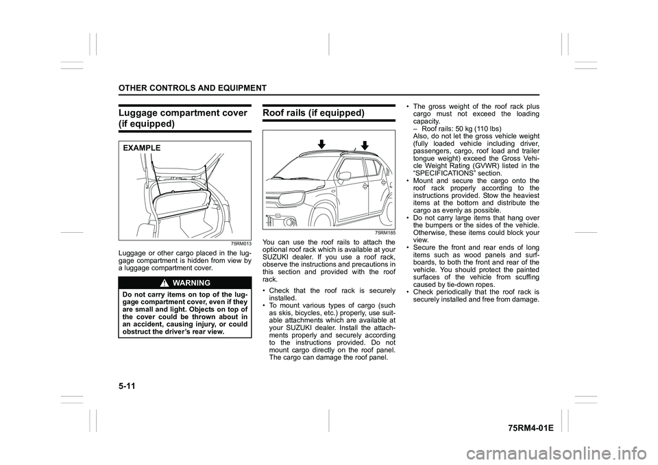
Luggage compartment cover (if equipped)
75RM013
Luggage or other cargo placed in the lug-
gage compartment is hidden from view by
a luggage compartment cover.
Roof rails (if equipped)
75RM185
You can use the roof rails to attach the
optional roof rack which is available at your
SUZUKI dealer. If you use a roof rack,
observe the instructions and precautions in
this section and provided with the roof
rack.
• Check that the roof rack is securelyinstalled.
• To mount various types of cargo (such
as skis, bicycles, etc.) properly, use suit-
able attachments which are available at
your SUZUKI dealer. Install the attach-
ments properly and securely according
to the instructions provided. Do not
mount cargo directly on the roof panel.
The cargo can damage the roof panel. • The gross weight of the roof rack plus
cargo must not exceed the loading
capacity.
– Roof rails: 50 kg (110 lbs)
Also, do not let the gross vehicle weight
(fully loaded vehicle including driver,
passengers, cargo, roof load and trailer
tongue weight) exceed the Gross Vehi-
cle Weight Rating (GVWR) listed in the
“SPECIFICATIO NS” section.
• Mount and secure the cargo onto the roof rack properly according to the
instructions provided. Stow the heaviest
items at the bottom and distribute the
cargo as evenly as possible.
• Do not carry large items that hang over the bumpers or the sides of the vehicle.
Otherwise, these items could block your
view.
• Secure the front and rear ends of long
items such as wood panels and surf-
boards, to both the front and rear of the
vehicle. You should protect the painted
surfaces of the vehicle from scuffing
caused by tie-down ropes.
• Check periodically that the roof rack is
securely installed and free from damage.
WA R N I N G
Do not carry items on top of the lug-
gage compartment cover, even if they
are small and light. Objects on top of
the cover could be thrown about in
an accident, causing injury, or could
obstruct the driver’s rear view.EXAMPLE
Page 342 of 505
6-1VEHICLE LOADING AND TOWING
75RM4-01E
Vehicle loadingYour vehicle was designed for specific
weight capacities. The weight capacities of
your vehicle are indicated by the Gross
Vehicle Weight Rating (GVWR) and the
Permissible maximum Axle Weight (PAW,
front and rear). The GVWR and PAW (front
and rear) are listed in the “SPECIFICA-
TIONS” section.
GVWR – Maximum permissible overall
weight of the fully loaded vehicle (including
all the occupants, accessories and cargo
plus the trailer nose weight if towing a
trailer).
PAW (front and rear) – Maximum permissi-
ble weight on an individual axle.
Actual weight of the loaded vehicle and
actual loads at the front and rear axles can
only be determined by weighing the vehi-
cle. Compare these weights to the GVWR
and PAW (front and rear). If the gross vehi-
cle weight or the load on either axle
exceeds these ratings, you must remove
enough weight to bring the load down to
the rated capacity.
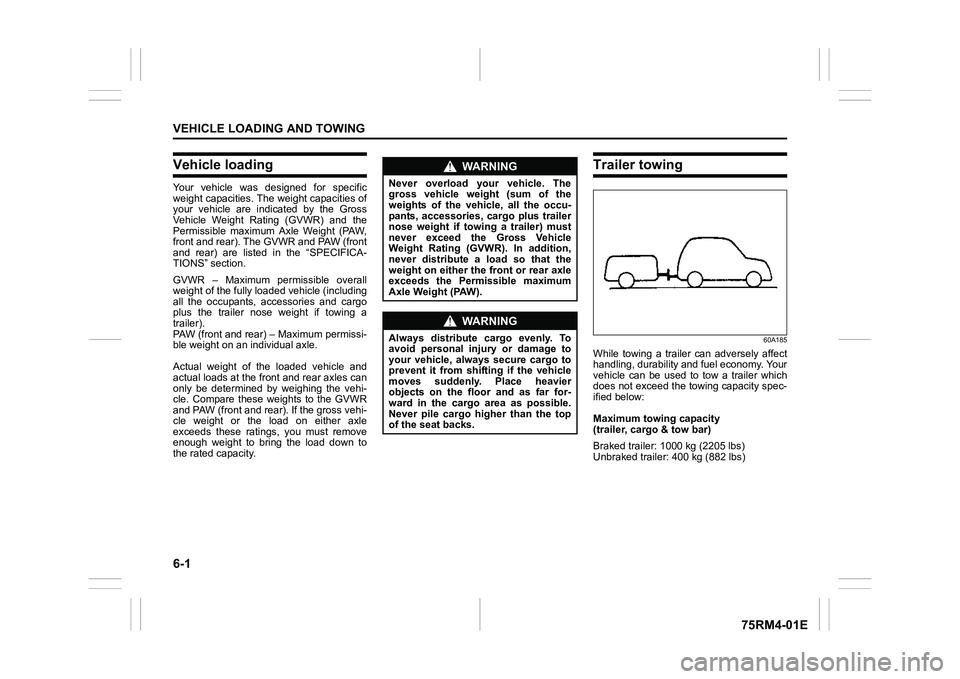
Trailer towing
60A185
While towing a trailer can adversely affect
handling, durability and fuel economy. Your
vehicle can be used to tow a trailer which
does not exceed the towing capacity spec-
ified below:
Maximum towing capacity
(trailer, cargo & tow bar)
Braked trailer: 1000 kg (2205 lbs)
Unbraked trailer: 400 kg (882 lbs)
WA R N I N G
Never overload your vehicle. The
gross vehicle weight (sum of the
weights of the vehicle, all the occu-
pants, accessories, cargo plus trailer
nose weight if towing a trailer) must
never exceed the Gross Vehicle
Weight Rating (GVWR). In addition,
never distribute a load so that the
weight on either the front or rear axle
exceeds the Permissible maximum
Axle Weight (PAW).
WA R N I N G
Always distribute cargo evenly. To
avoid personal injury or damage to
your vehicle, always secure cargo to
prevent it from shifting if the vehicle
moves suddenly. Place heavier
objects on the floor and as far for-
ward in the cargo area as possible.
Never pile cargo higher than the top
of the seat backs.
Page 344 of 505
6-3VEHICLE LOADING AND TOWING
75RM4-01E
TiresMirrorsCheck if your vehicle’s mirrors meet local
requirements for mirrors used on towing
vehicles. If they do not, you must install the
required mirrors before you tow.Vehicle/trailer loadingTo load your vehicle and trailer properly,
you must know how to measure gross
trailer weight and trailer nose weight.
Gross trailer weight is the weight of the
trailer plus all the cargo in it. You can mea-
sure gross trailer weight by putting the fully
loaded trailer on a vehicle scale.
Nose weight is the downward force
exerted on the tow bar by the trailer cou- pler, with the trailer fully loaded and the
coupler at its normal towing height. This
weight can be measured using a bathroom
scale.
The weight of your loaded trailer (gross
trailer weight) should never exceed towing
capacity.
Distribute cargo in your trailer so that nose
weight is about 10% of gross trailer weight,
but does not exceed “Maximum vertical
load” of 50 kg (110 lbs), and does not fall
below 25 kg (55 lbs) or 4%, whichever is
heavier, on trailer hitch point. You should
measure gross trailer weight and nose
weight before towing to check that your
load is properly distributed.
NOTE:
For 4WD model in Europe, in the Member
States where the road traffic legislation
allows it, as it is also stated in COMMIS-
SION REGULATION (EU) 1230/2012, the
technically permissi
ble maximum laden
mass (GVWR) of the vehicle may be
exceeded by not more than 40 kg (88 lbs)
in case of towing a trailer.
WA R N I N G
When towing a trailer, it is very
important for your vehicle and trailer
to have properly inflated tires. Your
vehicle’s tires should be inflated to
the pressures listed on your vehicles
tire information label. If laden pres-
sures are listed on the label, the tires
should be inflated to the laden pres-
sures. Inflate trailer tires according to
the specifications provided by the
trailer manufacturer.
WA R N I N G
Improper weight distribution of your
trailer may result in poor vehicle han-
dling and swaying of the trailer.
Always check that trailer nose weight
is about 10% of gross trailer weight,
but does not exceed “Maximum verti-
cal load” of 50 kg (110 lbs), and does
not fall below 25 kg (55 lbs) or 4%,
whichever is heavier, on trailer hitch
point. Also check that the cargo is
properly secured. Failure to observe
this requirement may result in an
accident.
WA R N I N G
Never overload cargo on your trailer
or your vehicle. Gross trailer weight
must never exceed towing capacity.
Gross vehicle weight (sum of the
weights of the vehicle, all the occu-
pants, accessories including tow
bars and a trailer hitch, cargo and
trailer nose weight) must never
exceed the Gross Vehicle Weight Rat-
ing (GVWR) listed in the “SPECIFICA-
TIONS” section.
Page 436 of 505
11-4SPECIFICATIONS
75RM4-01E
*1 If you cannot prepare tires with the specified load index rate and speed symbol, prepare tires with higher load index rate a nd speed
symbol.
*2 If you prepare snow tires;
• Check that they are tires of the same size, structure and load capacity as the originally installed tires.
• Mount the snow tires on all four wheels.
• Understand that the maximum pe rmissible speed of snow tires is generally less than the originally installed tires.
Consult your SUZUKI dealer or su pplier for further information.
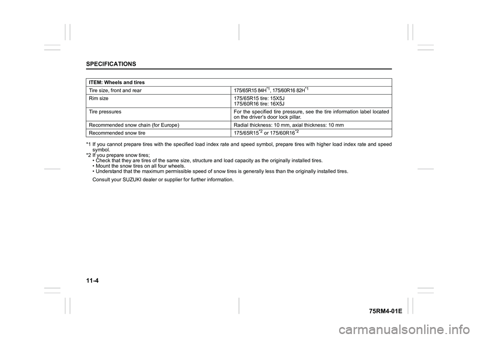
ITEM: Wheels and tires
Tire size, front and rear
175/65R15 84H
*1, 175/60R16 82H
*1
Rim size 175/65R15 tire: 15X5J
175/60R16 tire: 16X5J
Tire pressures For the specified tire pressure, see the tire information label located
on the driver’s door lock pillar.
Recommended snow chain (for Euro pe) Radial thickness: 10 mm, axi al thickness: 10 mm
Recommended snow tire 175/65R15
*2 or 175/60R16
*2