gears SUZUKI IGNIS 2021 Service Manual
[x] Cancel search | Manufacturer: SUZUKI, Model Year: 2021, Model line: IGNIS, Model: SUZUKI IGNIS 2021Pages: 505, PDF Size: 8.36 MB
Page 196 of 505
3-43OPERATING YOUR VEHICLE
75RM4-01E
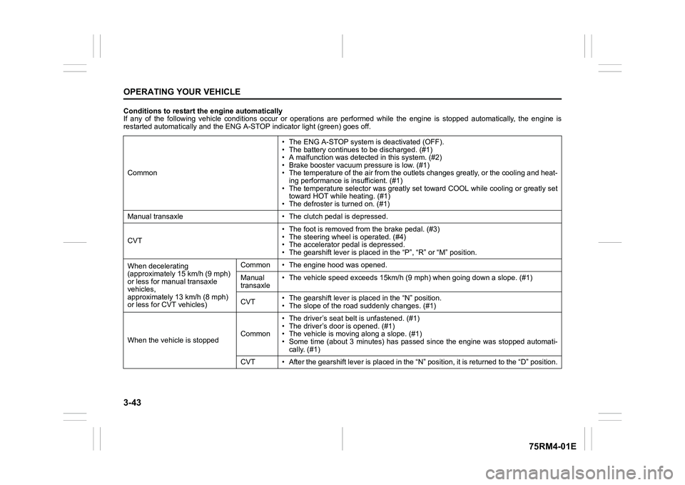
Conditions to restart the engine automatically
If any of the following vehicle conditions occur or operations are performed while the engine is stopped automatically, the en gine is
restarted automatically and the ENG A-STOP i ndicator light (green) goes off.
Common • The ENG A-STOP system is deactivated (OFF).
• The battery continues to be discharged. (#1)
• A malfunction was detect
ed in this system. (#2)
• Brake booster vacuum pressure is low. (#1)
• The temperature of the air from the outlets changes greatly, o r the cooling and heat-
ing performance is insufficient. (#1)
• The temperature selector was greatly set toward COOL while coo ling or greatly set
toward HOT while heating. (#1)
• The defroster is turned on. (#1)
Manual transaxle • The cl utch pedal is depressed.
CVT • The foot is removed from the brake pedal. (#3)
• The steering wheel is operated. (#4)
• The accelerator pedal is depressed.
• The gearshift lever is placed
in the “P”, “R” or “M” position.
When decelerating
(approximately 15 km/h (9 mph)
or less for manual transaxle
vehicles,
approximately 13 km/h (8 mph)
or less for CVT vehicles) Common • The engine hood was opened.
Manual
transaxle
• The vehicle speed exceeds 15km/
h (9 mph) when going down a slope. (#1)
CVT • The gearshift lever is placed in the “N” position.
• The slope of the road
suddenly changes. (#1)
When the vehicle is stopped Common• The driver’s seat
belt is unfastened. (#1)
• The driver’s door is opened. (#1)
• The vehicle is movi ng along a slope. (#1)
• Some time (about 3 minutes) has passed since the engine was st opped automati-
cally. (#1)
CVT • After the gearshift lever is placed in the “N” position, it is returned to the “D” position.
Page 200 of 505
3-47OPERATING YOUR VEHICLE
75RM4-01E
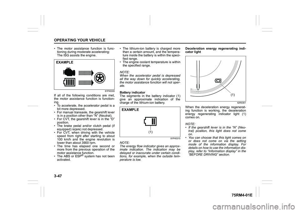
• The motor assistance function is func-tioning during moderate accelerating:
The ISG assists the engine.
81P40300
If all of the following conditions are met,
the motor assistance function is function-
ing.
• To accelerate, the accelerator pedal is a
bit more depressed.
• For manual transaxle, the gearshift lever is in a position other than “N” (Neutral).
• For CVT, the gearshift lever is in the “D” position.
• The brake pedal and/or clutch pedal (if
equipped) is(are) not depressed.
• For CVT, when driving with the vehicle speed from right after starting to about
100 km/h and the engine revolution is
lower than about 3900 rpm.
• The time has elapsed one second or
more from the previous operation of the
motor assistance function.
• The ABS or ESP
® system has not been
activated. • The lithium-ion battery is charged more
than a certain amount, and the tempera-
ture inside the battery is within the speci-
fied range.
• The engine coolant temperature is within the specified range.
NOTE:
When the accelerator pedal is depressed
all the way down for quickly accelerating,
the motor assistance function will not oper-
ate.
Battery indicator
The segments in the battery indicator (1)
give an approximate indication of the
charge of the lithium-ion battery.
81P40310
NOTE:
The energy flow indicator gives an approx-
imate indication. The indication may be
delayed or inaccurate under certain condi-
tions, for example, when the outside tem-
perature is low. Deceleration energy regenerating indi-
cator light
62R0361
When the deceleration energy regenerat-
ing function is working, the deceleration
energy regenerating indicator light (1)
comes on.
NOTE:
• If the gearshift lever is in the “N” (Neu-
tral) position, this light does not come
on.
• You can choose that this light comes on or does not come on via the setting
mode of the information display. For
details on how to use the information dis-
play, refer to “Informa tion display” in the
“BEFORE DRIVING” section.
EXAMPLE
(1)
EXAMPLE
(1)
Page 209 of 505
3-56
OPERATING YOUR VEHICLE
75RM4-01E
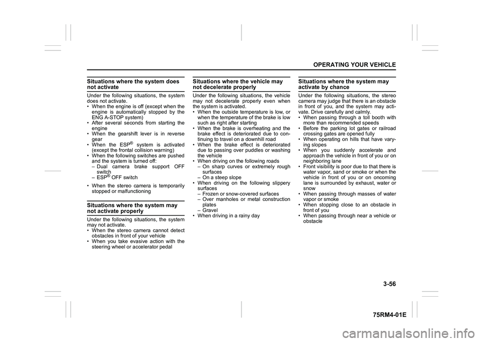
Situations where the system does not activateUnder the following situations, the system
does not activate.
• When the engine is off (except when theengine is automatically stopped by the
ENG A-STOP system)
• After several seconds from starting the
engine
• When the gearshift lever is in reverse gear
• When the ESP
® system is activated
(except the frontal collision warning)
• When the following switches are pushed
and the system is turned off:
– Dual camera brake support OFFswitch
– ESP
® OFF switch
• When the stereo camera is temporarily stopped or malfunctioning
Situations where the system may not activate properlyUnder the following situations, the system
may not activate.
• When the stereo camera cannot detectobstacles in front of your vehicle
• When you take evasive action with the
steering wheel or a ccelerator pedal
Situations where the vehicle may not decelerate properlyUnder the following situations, the vehicle
may not decelerate properly even when
the system is activated.
• When the outside temperature is low, or
when the temperature of the brake is low
such as right after starting
• When the brake is overheating and the brake effect is deteriorated due to con-
tinuing to travel on a downhill road
• When the brake effect is deteriorated due to passing over puddles or washing
the vehicle
• When driving on the following roads – On sharp curves or extremely roughsurfaces
– On a steep slope
• When driving on the following slippery surfaces
– Frozen or snow-covered surfaces
– Over manholes or metal constructionplates
–Gravel
• When driving in a rainy day
Situations where the system may activate by chanceUnder the following situations, the stereo
camera may judge that there is an obstacle
in front of you, and the system may acti-
vate. Drive carefully and calmly.
• When passing through a toll booth with more than recommended speeds
• Before the parking lot gates or railroad crossing gates are opened fully
• When operating on hills that have vary-
ing slopes
• When you suddenly accelerate and approach the vehicle in front of you or on
neighboring lane
• Front visibility is poor due to that there is water vapor, sand or smoke or when the
vehicle in front of you or on oncoming
lane is surrounded by exhaust, water or
snow
• When passing through masses of water vapor or smoke
• When stopping close to an obstacle in
front of you
• When passing through near a vehicle or obstacle
Page 225 of 505
3-72
OPERATING YOUR VEHICLE
75RM4-01E
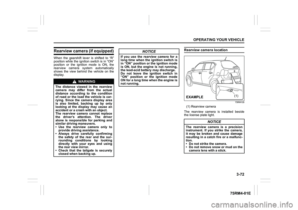
Rearview camera (if equipped)When the gearshift lever is shifted to “R”
position while the ignition switch is in “ON”
position or the ignition mode is ON, the
rearview camera system automatically
shows the view behind the vehicle on the
display.
Rearview camera location
75RM128
(1) Rearview camera
The rearview camera is installed beside
the license plate light.
WA R N I N G
The distance viewed in the rearview
camera may differ from the actual
distance according to the condition
of road or the load the vehicle is car-
rying. Since the camera display area
is also limited, backing up by only
looking at the display may cause an
accident or a crash with an object.
The rearview camera cannot replace
the driver’s attention. The driver
alone is responsible for parking and
similar driving maneuvers.
• Use the rearview camera only to provide driving assistance.
• Always drive carefully confirming
the safety of the rear and the sur-
rounding conditions by looking
directly with your eyes and using
the rear view mirror.
• Check that the tailgate is securely closed when backing up.
NOTICE
If you use the rearview camera for a
long time when the ignition switch is
in “ON” position or the ignition mode
is ON, but the engine is not running,
the lead-acid battery may discharge.
Do not leave the ignition switch in
“ON” position or the ignition mode
ON for a long time when the engine is
not running.
NOTICE
The rearview camera is a precision
instrument. If you strike the camera,
it may be broken and cause damage
resulting in a catch fire or a malfunc-
tion.
• Do not strike the camera.
• Do not remove snow or mud on thecamera lens with a stick.
(1)
�(�Ο�Ν�0�3�/�(
Page 226 of 505

3-73OPERATING YOUR VEHICLE
75RM4-01E
NOTE:
If body wax gets on the camera lens, wipe
off the wax with a clean cloth dampened
with mild detergent diluted with water, and
then wipe the lens with a dry cloth.
How to use rearview camera1) Turn the ignition switch to “ON” positionor press the engine switch to change
the ignition mode to ON.
2) Shift the gearshift lever in “R” position. • The display automatically shows the
view behind the vehicle.
• When the gearshift lever is shifted from “R” to another gearshift lever
position, the display returns to the
previous display.
NOTE:
The rearview camera display has first pri-
ority in any display mode. However, the
rearview camera display does not show
the rear view while the system is initializ-
ing.Display range of rearview cameraThe rearview camera display shows the
area behind the rear end of the tailgate.
The display cannot show objects which are
close to the bumper o r under the bumper.
The rearview camera display cannot show
obstacles which are higher than the cam-
era. Upper parts of tall objects such as
road signs cannot be viewed on the dis-
play. Display range of rearview camera
75RM293
54P000370
(1) Display range
NOTICE
If water enters the rearview camera, it
may cause a malfunction or catch
fire.
Do not use high pressure water
around the camera.
NOTICE
This lens is hard coated to prevent
damage or discoloration. Damage or
discoloration of lens may obscure
the image.
• Do not use a brush to clean lens.
• Do not use alcohol, benzene or thinner to clean the lens.
• Do not use wax on the camera lens.
(1)
EXAMPLE
(1)
EXAMPLE
Page 228 of 505
3-75OPERATING YOUR VEHICLE
75RM4-01E
If the rear view from the rearview cam-
era is not shown or there is a poor
image
• If the rear view from the rearview camerais not shown.
– Check that the ignition switch is in
“ON” position or the ignition mode is
ON.
– Check that the gearshift lever is
shifted to “R” position.
• If the image from the rearview camera is poor.
– Check that the camera lens is not dirty.
– Check that light from the sun or thebeam of the headlights from the vehi-
cle behind is not shining directly into
the lens.
If the rearview camera system is still not
working properly after checking the above,
have the system inspected by an autho-
rized SUZUKI dealer as soon as possible.
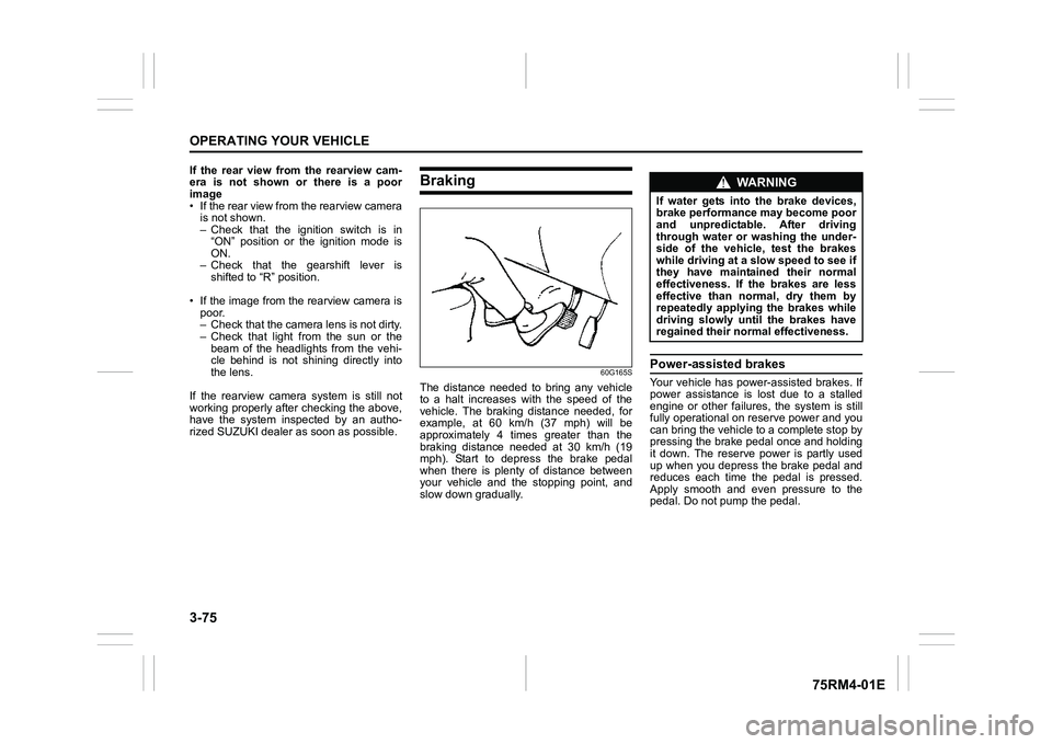
Braking
60G165S
The distance needed to bring any vehicle
to a halt increases with the speed of the
vehicle. The braking distance needed, for
example, at 60 km/h (37 mph) will be
approximately 4 times greater than the
braking distance needed at 30 km/h (19
mph). Start to depress the brake pedal
when there is plenty of distance between
your vehicle and the stopping point, and
slow down gradually.
Power-assisted brakesYour vehicle has power-assisted brakes. If
power assistance is lo st due to a stalled
engine or other failure s, the system is still
fully operational on reserve power and you
can bring the vehicle to a complete stop by
pressing the brake pedal once and holding
it down. The reserve power is partly used
up when you depress the brake pedal and
reduces each time the pedal is pressed.
Apply smooth and even pressure to the
pedal. Do not pump the pedal.
WA R N I N G
If water gets into the brake devices,
brake performance may become poor
and unpredictable. After driving
through water or washing the under-
side of the vehicle, test the brakes
while driving at a slow speed to see if
they have maintained their normal
effectiveness. If the brakes are less
effective than normal, dry them by
repeatedly applying the brakes while
driving slowly until the brakes have
regained their normal effectiveness.
Page 234 of 505

3-81OPERATING YOUR VEHICLE
75RM4-01E
Hill descent control switch
75RM056
(1) Hill descent control switch
To activate the hill descent control system:
1) Shift the gearshift lever into a forward
gear or reverse gear.2) Push the hill descent control switch (1) when the vehicle speed is under 25 km/h
(15 mph). The hill descent control indica-
tor on the instrument cluster will come on
and the hill descent control system will be
activated.
When the vehicle speed exceeds about 7
km/h (4 mph) without depressing the
accelerator pedal, the hill descent control
system applies the brak es automatically to
maintain the vehicle speed at about 7 km/h
(4 mph).
• When braking, the brake/tail lights come on and the ESP
® warning light blinks.
• When the vehicle speed exceeds about
40 km/h (25 mph), the hill descent con-
trol system stops functioning and the hill
descent control indicator goes off. When
the vehicle slows down below about 25
km/h (16 mph), the hill descent control
system will be activated again and the
hill descent control indicator will come
on.
NOTE:
You may hear a sound coming from the
engine when the hill descent control sys-
tem is activated. This sound is normal and
does not indicate a malfunction.
To turn off the hill descent control system,
push the hill descent control switch and
turn off the hill descent control indicator
light.
(1)
WA R N I N G
• When the hill descent control sys- tem is used continuously for a long
time, the temperature of the brake
system may increase and the hill
descent control system may be
deactivated tempor arily to protect
the device of the brake system. The
hill descent control indicator blinks
to let you know the system is deac-
tivated. Depress the brake pedal
and stop the vehicle in a safe place.
When the temperature of the brake
system goes down, the hill descent
control indicator will come on and
the system is activated again. (Continued)
WA R N I N G
(Continued)
• The hill descent control system
may be activated when the gear-
shift lever is in “N” (Neutral) posi-
tion, but engine braking will not
work. Always use the hill descent
control system with the gearshift
lever in a forward gear or reverse
gear.
• When using the hill descent control system, push the hill descent con-
trol switch and ma ke sure that the
hill descent control indicator light
comes on and no warning message
indicates on the information dis-
play.
• While operating the hill descent control system, the dual camera
brake support (if equipped) may
not operate depending on the
accelerating.
Page 235 of 505

3-82
OPERATING YOUR VEHICLE
75RM4-01E
Hill descent control indicator light
79K050
When the ignition switch is in “ON” posi-
tion, or the ignition mode is ON, this light
comes on briefly so you can check that the
light is working.
When you push the hill descent control
switch and the hill descent control operat-
ing conditions are fulfilled, the hill descent
control indicator comes on. If the hill
descent control indicator blinks, the hill
descent control will not be activated.
If hill descent control indicator light comes
on while not operating the hill descent con-
trol switch, or the indicator light does not
come on after the switch is pushed, there
is a problem in this system. Have your
vehicle inspected by an authorized
SUZUKI dealer. NOTE:
If the hill descent control indicator blinks
when you push the hill descent control
switch, the following conditions may not be
fulfilled.
• The gearshift lever is in a forward gear
or reverse gear
• The vehicle speed is under 25 km/h (15 mph)
• The brake system is under normal oper- ating temperature
NOTE:
If any of the followin g conditions occur,
there may be a problem with the hill
descent control system or the ESP
® sys-
tem. Have your vehicle inspected by an
authorized SUZUKI dealer.
• The hill descent control indicator does not come on or blink when you push the
hill descent co ntrol switch.
• The hill descent control indicator stays on when driving without pushing the hill
descent control switch.
75RM224
For the instrument cluster with tachometer,
if the message shown in the above illustra-
tion appears on the information display,
there may be a problem with the hill
descent control system and the hill hold
control system. Ha ve your vehicle
inspected by an authorized SUZUKI
dealer.
NOTE:
You cannot activate the hill descent control
system while this me ssage is displayed.
Page 237 of 505
3-84
OPERATING YOUR VEHICLE
75RM4-01E
How grip control system works
When the grip control switch is on and one
side of the tires is slipping, the grip control
system assists you in smooth starting by
controlling the driving force and brake
force of all wheels.
• When the ESP
® system is off, the grip
control system cannot be activated.
NOTE:
While the grip control system is working,
the ESP
® warning light blinks.
Hill hold control sys tem (if equipped)The hill hold control system is designed to
assist you in starting to move up hills.
When you start to move up a hill, the sys-
tem helps to prevent the vehicle from roll-
ing downward (for approximately 2
seconds) while you move your foot from
the brake pedal to the accelerator pedal.
The hill hold control system activates for a
maximum of about 2 seconds if your foot is
moved from the brake pedal when the fol-
lowing conditions are all met.
1) The gearshift lever is in a forward gear or reverse gear.
2) The parking brake is released.
3) For manual transaxle models, the clutch pedal is depressed.
4) The vehicle is o n an upward incline.
CAUTION
To activate the grip control system,
push the grip control switch and
check that the indicator on the switch
turns on.
WA R N I N G
• Do not rely excessively on the hill
hold control system. The hill hold
control system may not prevent the
vehicle from rolling downward on a
hill under all load or road condi-
tions. Always be prepared to
depress the brake pedal to prevent
the vehicle from rolling downward.
Failure to pay attention and
depress the brake pedal to hold the
vehicle on a hill when necessary,
may result in loss of control or an
accident.
• The hill hold control system is not designed to stop the vehicle on a
hill. (Continued)
WA R N I N G
(Continued)
• After you release your foot from the
brake pedal, accelerate the vehicle
to move up immediately. If you
release your foot from the brake
pedal over 2 seconds, the hill hold
control system will be canceled. If
so, the vehicle may roll downward,
which can result in an accident
depending on the degree of slope.
And, the engine may stall and the
power assist for the steering and
brakes will not work so steering
and braking will be much harder
than usual which can result in an
accident or vehicle damage.
Page 264 of 505
5-9OTHER CONTROLS AND EQUIPMENT
75RM4-01E
Center console tray (1)
Front cup holders (2) / Rear cup holder (5)Use the rear cup holder to put a cup with a
lid or a bottle with a cap. Also, you can put
small articles in the rear cup holder.
Front bottle holder (3) / Rear bottle holder (6)You should only place a bottle with a cap in
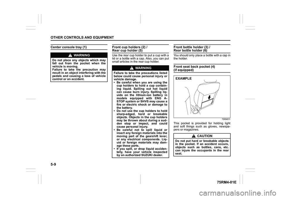
the holder.Front seat back pocket (4) (if equipped)
75RM011
This pocket is provided for holding light
and soft things such as gloves, newspa-
pers or magazines.
WA R N I N G
Do not place any objects which may
fall out from the pocket when the
vehicle is moving.
Failure to take the precaution may
result in an object interfering with the
pedals and causing a loss of vehicle
control or an accident.
WA R N I N G
Failure to take the precautions listed
below could cause personal injury or
vehicle damage.
• Be careful when you are using the
cup holders to hold a cup contain-
ing liquid. Spilling out hot liquid
can cause burn injury. Spilling liq-
uids on the lithium-ion battery in
models equipped with ENG A-
STOP system or SHVS may cause a
fire or electric shock or damage to
the battery.
• Do not use the cup holders to hold sharp-edged, hard or breakable
objects. Objects in the cup holders
may be thrown about during a sud-
den stop or impact, and could
cause personal injury.
• Be careful not to spill liquid or insert any foreign materials into the
moving part of the gearshift lever,
or any electrical components. Liq-
uid or foreign materials may dam-
age these parts.
• If you spill, or drop liquid acciden- tally, have your vehicle inspected
by an authorized SUZUKI dealer.
CAUTION
Do not put hard or breakable objects
in the pocket. If an accident occurs,
objects such as bottles, cans, etc.
can injure the occupants in the rear
seat.EXAMPLE