ECU SUZUKI IGNIS 2022 Owner's Manual
[x] Cancel search | Manufacturer: SUZUKI, Model Year: 2022, Model line: IGNIS, Model: SUZUKI IGNIS 2022Pages: 505, PDF Size: 8.36 MB
Page 225 of 505
3-72
OPERATING YOUR VEHICLE
75RM4-01E
Rearview camera (if equipped)When the gearshift lever is shifted to “R”
position while the ignition switch is in “ON”
position or the ignition mode is ON, the
rearview camera system automatically
shows the view behind the vehicle on the
display.
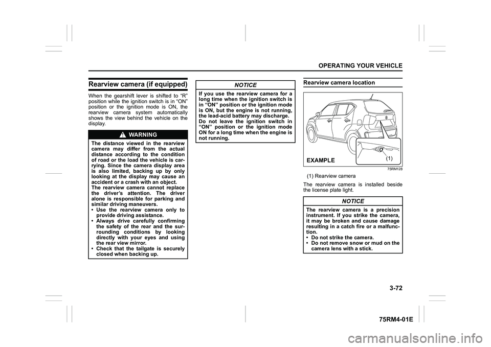
Rearview camera location
75RM128
(1) Rearview camera
The rearview camera is installed beside
the license plate light.
WA R N I N G
The distance viewed in the rearview
camera may differ from the actual
distance according to the condition
of road or the load the vehicle is car-
rying. Since the camera display area
is also limited, backing up by only
looking at the display may cause an
accident or a crash with an object.
The rearview camera cannot replace
the driver’s attention. The driver
alone is responsible for parking and
similar driving maneuvers.
• Use the rearview camera only to provide driving assistance.
• Always drive carefully confirming
the safety of the rear and the sur-
rounding conditions by looking
directly with your eyes and using
the rear view mirror.
• Check that the tailgate is securely closed when backing up.
NOTICE
If you use the rearview camera for a
long time when the ignition switch is
in “ON” position or the ignition mode
is ON, but the engine is not running,
the lead-acid battery may discharge.
Do not leave the ignition switch in
“ON” position or the ignition mode
ON for a long time when the engine is
not running.
NOTICE
The rearview camera is a precision
instrument. If you strike the camera,
it may be broken and cause damage
resulting in a catch fire or a malfunc-
tion.
• Do not strike the camera.
• Do not remove snow or mud on thecamera lens with a stick.
(1)
�(�Ο�Ν�0�3�/�(
Page 252 of 505
4-5DRIVING TIPS
75RM4-01E
Tire chainsTire chains should only be used if they are
needed to increase traction or are required
by law. Check that the chains you use are
the correct size for your vehicle’s tires.
Also check that there is enough clearance
between the fenders and the chains as
installed on the tires.
Install the chains on the front tires tightly,
according to the chain manufacturer’s
instructions. Retighten the chains after
driving about 1.0 km (1/2 mile) if neces-
sary. With the chains installed, drive slowly.
Stuck vehicleIf your vehicle gets stuck in snow, mud or
sand, follow the directions below:
1) Shift the transaxle back and forthbetween a forward range (or first gear
for manual transaxle/Auto Gear Shift)
and reverse. This will create a rocking
motion which may give you enough
momentum to free the vehicle. Press
gently on the accelerator to keep wheel
spinning to a minimum wheel rpm.
Remove your foot from the accelerator
while shifting.
Do not race the engine. Excessive
wheel spin will cause the tires to dig
deeper, making it more difficult to free
the vehicle.
NOTE:
If your vehicle is equipped with the ESP
®
and/or grip control system, you may have
to turn the systems off in order to spin the
wheels. 2) If your vehicle rema
ins stuck after a few
minutes of rocking, we recommend you
to consult your SUZUKI dealer or a road-
side assistance service. If a towing ser-
vice is not available in an emergency,
your vehicle may be temporarily towed by
a towing cable or chain secured to the
towing hook either on the front of the
vehicle or on the rear of the vehicle. Refer
to “Frame hooks” in the “OTHER CON-
TROLS AND EQUIPMENT” section.
NOTICE
• If you hear the chains hitting against the vehicle body while driv-
ing, stop and tighten them.
• If your vehicle is equipped with full wheel caps, remove the wheel caps
before installing the chains or the
wheel caps can be damaged by the
chain bands.
WA R N I N G
Do not allow anyone to stand near
the vehicle when you are rocking it,
and do not spin the wheels faster
than an indicated 40 km/h (25 mph)
on the speedometer. Personal injury
and/or vehicle damage may result
from spinning the wheels too fast.
NOTICE
Do not continue rocking the vehicle
for more than a few minutes. Pro-
longed rocking can cause engine
overheating or transaxle damage.
Page 258 of 505

5-3OTHER CONTROLS AND EQUIPMENT
75RM4-01E
75RM133
3) While holding the hood, pull the proprod out from the holding clip, and then
insert the end of the rod into the desig-
nated hole in the hood. To close the engine hood:
1) Lift the hood up slightly and remove the
prop rod from the hole. Put the prop rod
back into the holding clip.
62R0074
2) Lower the hood to about 20 cm above
the hood latch, and then let it drop
down. Check that the hood is securely
latched after closing.
CAUTION
• The prop rod can be hot enough toburn your finger right after driving.
Touch the rod after it becomes cool
enough.
• Insert the end of the rod into the hole securely. If the rod slips out,
you may get caught in the closing
hood.
• The rod may slip out when the
hood is blown by wind. Be careful
on windy days.
EXAMPLE
WA R N I N G
Check that the hood is fully closed
and latched before d riving. If it is not,
it can fly up unexpectedly during
driving, obstructing your view and
resulting in an accident.
EXAMPLE
CAUTION
To avoid injury, check that no part of
the occupant’s body such as hands
or head is in the path of the hood
when closing it.
NOTICE
Pushing on the hood from the top
may damage it.
Page 262 of 505
5-7OTHER CONTROLS AND EQUIPMENT
75RM4-01E
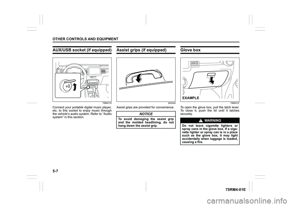
AUX/USB socket (if equipped)
75RM170
Connect your portable digital music player,
etc. to this socket to enjoy music through
the vehicle’s audio system. Refer to “Audio
system” in this section.
Assist grips (if equipped)
54G249
Assist grips are provided for convenience.
Glove box
75RM137
To open the glove box, pull the latch lever.
To close it, push the lid until it latches
securely.
NOTICE
To avoid damaging the assist grip
and the molded headlining, do not
hang down the assist grip.
WA R N I N G
Do not leave cigarette lighters or
spray cans in the glove box. If a ciga-
rette lighter or spray can is in a place
such as the glove box, it may light
accidentally when luggage is loaded,
causing a fire.EXAMPLE
Page 266 of 505
5-11OTHER CONTROLS AND EQUIPMENT
75RM4-01E
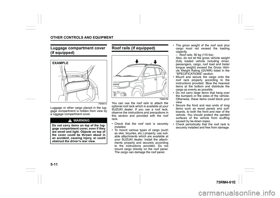
Luggage compartment cover (if equipped)
75RM013
Luggage or other cargo placed in the lug-
gage compartment is hidden from view by
a luggage compartment cover.
Roof rails (if equipped)
75RM185
You can use the roof rails to attach the
optional roof rack which is available at your
SUZUKI dealer. If you use a roof rack,
observe the instructions and precautions in
this section and provided with the roof
rack.
• Check that the roof rack is securelyinstalled.
• To mount various types of cargo (such
as skis, bicycles, etc.) properly, use suit-
able attachments which are available at
your SUZUKI dealer. Install the attach-
ments properly and securely according
to the instructions provided. Do not
mount cargo directly on the roof panel.
The cargo can damage the roof panel. • The gross weight of the roof rack plus
cargo must not exceed the loading
capacity.
– Roof rails: 50 kg (110 lbs)
Also, do not let the gross vehicle weight
(fully loaded vehicle including driver,
passengers, cargo, roof load and trailer
tongue weight) exceed the Gross Vehi-
cle Weight Rating (GVWR) listed in the
“SPECIFICATIO NS” section.
• Mount and secure the cargo onto the roof rack properly according to the
instructions provided. Stow the heaviest
items at the bottom and distribute the
cargo as evenly as possible.
• Do not carry large items that hang over the bumpers or the sides of the vehicle.
Otherwise, these items could block your
view.
• Secure the front and rear ends of long
items such as wood panels and surf-
boards, to both the front and rear of the
vehicle. You should protect the painted
surfaces of the vehicle from scuffing
caused by tie-down ropes.
• Check periodically that the roof rack is
securely installed and free from damage.
WA R N I N G
Do not carry items on top of the lug-
gage compartment cover, even if they
are small and light. Objects on top of
the cover could be thrown about in
an accident, causing injury, or could
obstruct the driver’s rear view.EXAMPLE
Page 267 of 505
5-12
OTHER CONTROLS AND EQUIPMENT
75RM4-01E
Frame hooksYour SUZUKI does not recommend you
use the frame hooks for towing another
vehicle. SUZUKI was originally designed to
tow your vehicle on the road emergency
towing.
If your vehicle needs to be towed in an
emergency, refer to “Towing” in the
“EMERGENCY SERVICE” section.
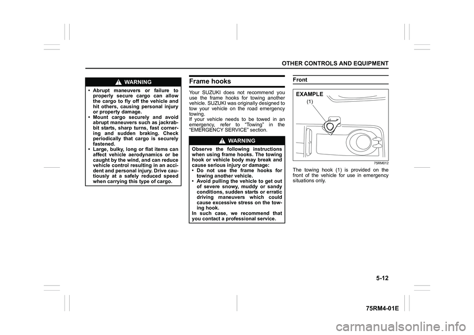
Front
75RM012
The towing hook (1) is provided on the
front of the vehicle for use in emergency
situations only.
WA R N I N G
• Abrupt maneuvers or failure toproperly secure cargo can allow
the cargo to fly off the vehicle and
hit others, causing personal injury
or property damage.
• Mount cargo securely and avoid abrupt maneuvers such as jackrab-
bit starts, sharp turns, fast corner-
ing and sudden braking. Check
periodically that cargo is securely
fastened.
• Large, bulky, long or flat items can affect vehicle aerodynamics or be
caught by the wind, and can reduce
vehicle control resulting in an acci-
dent and personal injury. Drive cau-
tiously at a safely reduced speed
when carrying this type of cargo.
WA R N I N G
Observe the following instructions
when using frame hooks. The towing
hook or vehicle body may break and
cause serious injury or damage:
• Do not use the frame hooks fortowing another vehicle.
• Avoid pulling the vehicle to get out
of severe snowy, muddy or sandy
conditions, sudden starts or erratic
driving maneuvers which could
cause excessive stress on the tow-
ing hook.
In such case, we recommend that
you contact a professional service.
(1)
EXAMPLE
Page 269 of 505
5-14
OTHER CONTROLS AND EQUIPMENT
75RM4-01E
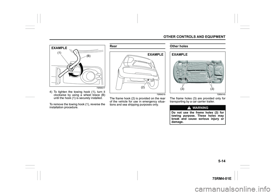
75RM017
4) To tighten the towing hook (1), turn itclockwise by using a wheel brace (B)
until the hook (1) is securely installed.
To remove the towing hook (1), reverse the
installation procedure.
Rear
75RM018
The frame hook (2) is provided on the rear
of the vehicle for use in emergency situa-
tions and sea shipping purposes only.
Other holes
75RM140
The frame holes (3) are provided only for
transporting by a car carrier trailer.
(B)
(1)
EXAMPLE
(2)
EXAMPLE
WA R N I N G
Do not use the frame holes (3) for
towing purpose. These holes may
break and cause serious injury or
damage.
(3) (3)
�(�Ο�Ν�0�3�/�(
Page 327 of 505
5-72
OTHER CONTROLS AND EQUIPMENT
75RM4-01E
Selection of phone (Select Phone)
Follow the instructions below to select a
phone to be paired with from the registered
phones.
1) Press the Bluetooth
® setup button (5)
or (6).
The Bluetooth
® setup menu will be dis-
played.
2) Turn “TUNE/FLD PUSH SOUND” knob
(1) to select “Setup Bluetooth”, and
press the knob (1) to determine the
selection.
3) Turn “TUNE/FLD PUSH SOUND” knob (1) to select “List Phone”, and press the
knob (1) to determine the selection.
4) Turn “TUNE/FLD PUSH SOUND” knob (1) to select a phone to be paired with,
and press the knob (1) to determine the
selection.
5) Turn “TUNE/FLD PUSH SOUND” knob
(1) to select “Select”, and press the
knob (1) to determine the selection.
NOTE:
• When selecting “Go Back” or pressing BACK button (4), the previous menu will
be displayed.
• The Bluetooth® ready audio device will
be disconnected when the phone is
selected. List of phones (List Phones)
Follow the instructions below to display the
names of the registered phones in
sequence.
1) Press the Bluetooth
® setup button (5)
or (6).
The Bluetooth
® setup menu will be dis-
played.
2) Turn “TUNE/FLD PUSH SOUND” knob
(1) to select “Setup Bluetooth”, and
press the knob (1) to determine the
selection.
3) Turn “TUNE/FLD PUSH SOUND” knob (1) to select “List Phone”, and press the
knob (1) to determine the selection.
The names of the registered phones
are displayed in sequence.
NOTE:
When selecting “Go Back” or pressing
BACK button (4), the previous menu will
be displayed.
Passkey setting (Set Passkey)
Follow the instructions below to set the
security number (passkey).
1) Press the Bluetooth
® setup button (5)
or (6).
The Bluetooth
® setup menu will be dis-
played.
2) Turn “TUNE/FLD PUSH SOUND” knob (1) to select “Setup Bluetooth”, and
press the knob (1) to determine the
selection. 3) Turn “TUNE/FLD PUSH SOUND” knob
(1) to select “Passkey”, and press the
knob (1) to determine the selection.
4) Turn “TUNE/FLD PUSH SOUND” knob (1) to select “Enter New Passkey”, and
press the knob (1) to determine the
selection.
5) Press or turn “TUNE/FLD PUSH SOUND” knob (1) to select “Confirm”.
6) Turn “TUNE/FLD PUSH SOUND” knob (1) to select a number for the first digit,
and press the knob (1) to determine the
selection. Select and determine num-
bers for the second, third and fourth
digits in order in the same manner.
When not entering up to the eighth
digit, enter blanks for the successive
digits.
7) Press “TUNE/FLD PUSH SOUND” knob (1) to determine the passkey set-
ting.
NOTE:
When selecting “Go Back” or pressing
BACK button (4), the previous menu will
be displayed.
Page 331 of 505
5-76
OTHER CONTROLS AND EQUIPMENT
75RM4-01E
Selection of audio device (Select Audio)
Follow the instructions below to select an
audio device to be paired with from the
registered audio devices.
1) Press the Bluetooth
® setup button (7)
or (8).
The Bluetooth
® setup menu will be dis-
played.
2) Turn “TUNE/FLD PUSH SOUND” knob
(2) to select “Setup Bluetooth”, and
press the knob (2) to determine the
selection.
3) Turn “TUNE/FLD PUSH SOUND” knob (2) to select “List Audio”, and press the
knob (2) to determine the selection.
4) Turn “TUNE/FLD PUSH SOUND” knob (2) to select an audio device to be
used, and press the knob (2) to deter-
mine the selection.
5) Turn “TUNE/FLD PUSH SOUND” knob
(2) to select “Select”, and press the
knob (2) to determine the selection.
NOTE:
• When selecting “Go Back” or pressing BACK button (6), the previous menu will
be displayed.
• The phone will be disconnected when the Bluetooth® ready audio device is
selected. List of audio devices (List Audio)
Follow the instructions below to display the
names of the registered audio devices in
sequence.
1) Press the Bluetooth
® setup button (7)
or (8).
The Bluetooth
® setup menu will be dis-
played.
2) Turn “TUNE/FLD PUSH SOUND” knob
(2) to select “Setup Bluetooth”, and
press the knob (2) to determine the
selection.
3) Turn “TUNE/FLD PUSH SOUND” knob (2) to select “List Audio”, and press the
knob (2) to determine the selection.
The names of registered audio devices
will be displayed in sequence.
NOTE:
When selecting “Go Back” or pressing
BACK button (6), the previous menu will
be displayed.
Passkey setting (Set Passkey)
Follow the instructions below to set the
security number (Passkey).
1) Press the Bluetooth
® setup button (7)
or (8).
The Bluetooth
® setup menu will be dis-
played.
2) Turn “TUNE/FLD PUSH SOUND” knob (2) to select “Setup Bluetooth”, and
press the knob (2) to determine the
selection. 3) Turn “TUNE/FLD PUSH SOUND” knob
(2) to select “Passkey”, and press the
knob (2) to determine the selection.
4) Turn “TUNE/FLD PUSH SOUND” knob (2) to select “Enter New Passkey”, and
press the knob (2) to determine the
selection.
5) Press or turn “TUNE/FLD PUSH SOUND” knob (2) to select “Confirm”.
6) Turn “TUNE/FLD PUSH SOUND” knob (2) to select a number for the first digit,
and press the knob (2) to determine the
selection. Select and determine num-
bers for the second, third and fourth
digits in order in the same manner.
When not entering up to the eighth
digit, enter blanks for the successive
digits.
7) Press “TUNE/FLD PUSH SOUND” knob (2) to determine the passkey set-
ting.
NOTE:
When selecting “Go Back” or pressing
BACK button (6), the previous menu will
be displayed.
Page 335 of 505
![SUZUKI IGNIS 2022 Owners Manual 5-80
OTHER CONTROLS AND EQUIPMENT
75RM4-01E
Setting the anti-theft function
1) Press “VOL PUSH PWR” knob (1) to power off.
2) Hold down the buttons numbered [1] and [6] of PRESET b SUZUKI IGNIS 2022 Owners Manual 5-80
OTHER CONTROLS AND EQUIPMENT
75RM4-01E
Setting the anti-theft function
1) Press “VOL PUSH PWR” knob (1) to power off.
2) Hold down the buttons numbered [1] and [6] of PRESET b](/img/20/43482/w960_43482-334.png)
5-80
OTHER CONTROLS AND EQUIPMENT
75RM4-01E
Setting the anti-theft function
1) Press “VOL PUSH PWR” knob (1) to power off.
2) Hold down the buttons numbered [1] and [6] of PRESET buttons (2) and
press “VOL PUSH PWR” knob (1).
“SECURITY” will be displayed.
3) Press UP button (3) and the button numbered [1] of P RESET buttons (2)
simultaneously.
4) Enter a 4-digit number to be registered as PIN using the buttons numbered [1]
- [4] of PRESET buttons (2).
5) Hold down “TUNE/FLD PUSH
SOUND” knob (4) for 1 second or lon-
ger to set the anti-theft function.
NOTE:
Take a note of the registered PIN and keep
it for the future use. Canceling the anti-theft feature
To cancel the anti-theft function, delete the
registered PIN.
1) Press “VOL PUSH PWR” knob (1) to
power off.
2) Hold down the buttons numbered [1]
and [6] of PRESET buttons (2) and
press “VOL PUSH PWR” knob (1).
“PIN ENTRY” will be displayed.
3) Press UP button (3) and the button numbered [1] of P RESET buttons (2)
simultaneously.
4) Enter a 4-digit number to be registered as PIN using the buttons numbered [1]
- [4] of PRESET buttons (2).
5) Hold down “TUNE/FLD PUSH SOUND” knob (4) for 1 second or lon-
ger to delete the registered PIN. The
indication “----” will be displayed and
the anti-theft function will be canceled.
NOTE:
To change your PIN, first delete your cur-
rent PIN, and then set a new one. Confirming the Personal Identification
Number (PIN)
When the main power source is discon-
nected such as when the lead-acid battery
is replaced, etc, it is required to enter the
PIN to operate
the unit again.
1) Set the ignition switch to “ACC” posi- tion or the ignition mode to ON.
“SECURITY” will be displayed.
2) Press UP button (3) and the button numbered [1] of P RESET buttons (2)
simultaneously.
3) Enter a 4-digit number to be registered as PIN using the buttons numbered [1]
- [4] of PRESET buttons (2).
4) Hold down “TUNE/FLD PUSH SOUND” knob (4) for 1 second or lon-
ger.
When the same PIN as registered is
entered, the power of the audio system
will be turned off automatically and it
will become operable again.
NOTE:
If an incorrect PIN is entered, “ERROR”
and the total number of incorrect entry
attempts will be displayed.
If an incorrect PIN is entered 10 times or
more, “HELP” will be displayed and the
audio system will become inoperable.