check engine SUZUKI IGNIS 2022 Repair Manual
[x] Cancel search | Manufacturer: SUZUKI, Model Year: 2022, Model line: IGNIS, Model: SUZUKI IGNIS 2022Pages: 505, PDF Size: 8.36 MB
Page 241 of 505
3-88
OPERATING YOUR VEHICLE
75RM4-01E
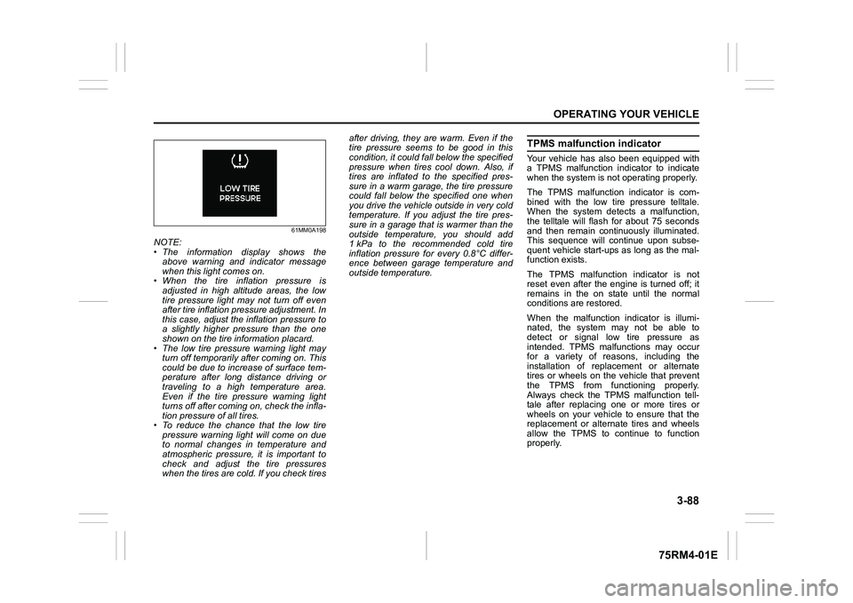
61MM0A198
NOTE:
• The information display shows theabove warning and indicator message
when this light comes on.
• When the tire inflation pressure is
adjusted in high altitude areas, the low
tire pressure light may not turn off even
after tire inflation pressure adjustment. In
this case, adjust the inflation pressure to
a slightly higher pressure than the one
shown on the tire information placard.
• The low tire pressure warning light may turn off temporarily after coming on. This
could be due to increase of surface tem-
perature after long distance driving or
traveling to a high temperature area.
Even if the tire pressure warning light
turns off after coming on, check the infla-
tion pressure of all tires.
• To reduce the chance that the low tire pressure warning light will come on due
to normal changes in temperature and
atmospheric pressure, it is important to
check and adjust the tire pressures
when the tires are cold. If you check tires after driving, they are warm. Even if the
tire pressure seems to be good in this
condition, it could fall below the specified
pressure when tires cool down. Also, if
tires are inflated to the specified pres-
sure in a warm garage, the tire pressure
could fall below the specified one when
you drive the vehicle outside in very cold
temperature. If you adjust the tire pres-
sure in a garage that is warmer than the
outside temperature, you should add
1 kPa to the recommended cold tire
inflation pressure for every 0.8°C differ-
ence between garage temperature and
outside temperature.
TPMS malfunction indicatorYour vehicle has also been equipped with
a TPMS malfunction indicator to indicate
when the system is not operating properly.
The TPMS malfunction indicator is com-
bined with the low tire pressure telltale.
When the system detects a malfunction,
the telltale will flash for about 75 seconds
and then remain continuously illuminated.
This sequence will continue upon subse-
quent vehicle start-ups as long as the mal-
function exists.
The TPMS malfunction indicator is not
reset even after the engine is turned off; it
remains in the on state until the normal
conditions are restored.
When the malfunction indicator is illumi-
nated, the system may not be able to
detect or signal low tire pressure as
intended. TPMS malfunctions may occur
for a variety of reasons, including the
installation of replacement or alternate
tires or wheels on the vehicle that prevent
the TPMS from functioning properly.
Always check the TPMS malfunction tell-
tale after replacing one or more tires or
wheels on your vehicle to ensure that the
replacement or alternate tires and wheels
allow the TPMS to continue to function
properly.
Page 252 of 505
4-5DRIVING TIPS
75RM4-01E
Tire chainsTire chains should only be used if they are
needed to increase traction or are required
by law. Check that the chains you use are
the correct size for your vehicle’s tires.
Also check that there is enough clearance
between the fenders and the chains as
installed on the tires.
Install the chains on the front tires tightly,
according to the chain manufacturer’s
instructions. Retighten the chains after
driving about 1.0 km (1/2 mile) if neces-
sary. With the chains installed, drive slowly.
Stuck vehicleIf your vehicle gets stuck in snow, mud or
sand, follow the directions below:
1) Shift the transaxle back and forthbetween a forward range (or first gear
for manual transaxle/Auto Gear Shift)
and reverse. This will create a rocking
motion which may give you enough
momentum to free the vehicle. Press
gently on the accelerator to keep wheel
spinning to a minimum wheel rpm.
Remove your foot from the accelerator
while shifting.
Do not race the engine. Excessive
wheel spin will cause the tires to dig
deeper, making it more difficult to free
the vehicle.
NOTE:
If your vehicle is equipped with the ESP
®
and/or grip control system, you may have
to turn the systems off in order to spin the
wheels. 2) If your vehicle rema
ins stuck after a few
minutes of rocking, we recommend you
to consult your SUZUKI dealer or a road-
side assistance service. If a towing ser-
vice is not available in an emergency,
your vehicle may be temporarily towed by
a towing cable or chain secured to the
towing hook either on the front of the
vehicle or on the rear of the vehicle. Refer
to “Frame hooks” in the “OTHER CON-
TROLS AND EQUIPMENT” section.
NOTICE
• If you hear the chains hitting against the vehicle body while driv-
ing, stop and tighten them.
• If your vehicle is equipped with full wheel caps, remove the wheel caps
before installing the chains or the
wheel caps can be damaged by the
chain bands.
WA R N I N G
Do not allow anyone to stand near
the vehicle when you are rocking it,
and do not spin the wheels faster
than an indicated 40 km/h (25 mph)
on the speedometer. Personal injury
and/or vehicle damage may result
from spinning the wheels too fast.
NOTICE
Do not continue rocking the vehicle
for more than a few minutes. Pro-
longed rocking can cause engine
overheating or transaxle damage.
Page 257 of 505
5-2
OTHER CONTROLS AND EQUIPMENT
75RM4-01E
To reinstall the fuel filler cap:
1) Turn the cap clockwise until you hearseveral clicks.
2) Close the fuel filler door.
Engine hood
75RM131
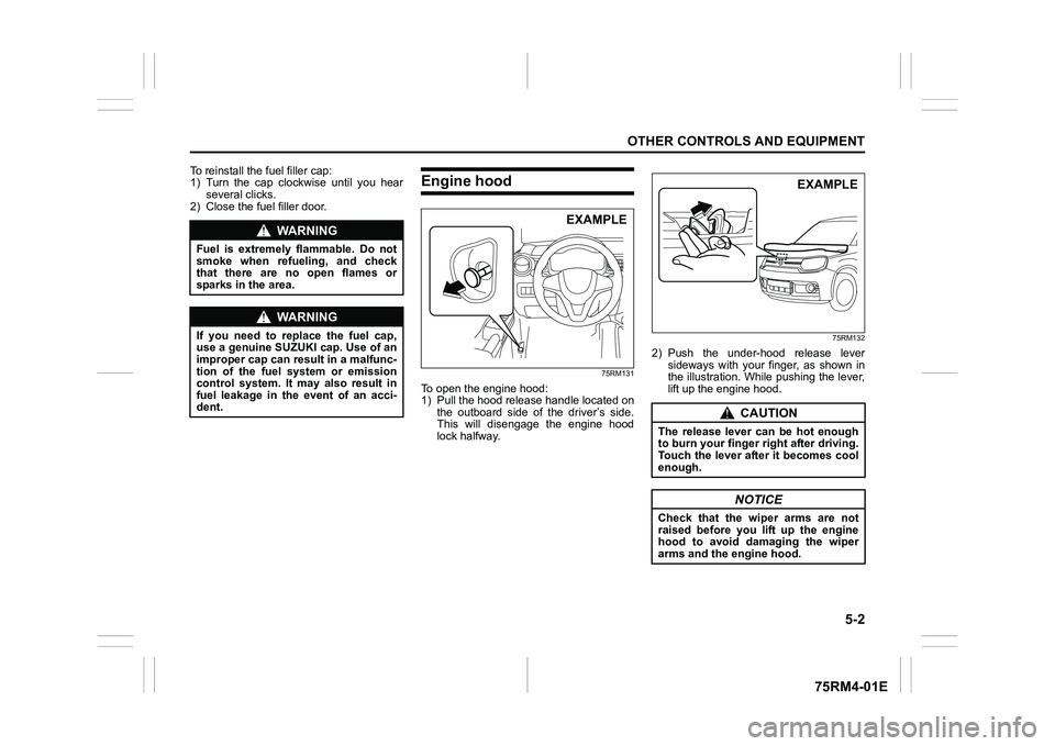
To open the engine hood:
1) Pull the hood release handle located on the outboard side of the driver’s side.
This will disengage the engine hood
lock halfway.
75RM132
2) Push the under-hood release leversideways with your finger, as shown in
the illustration. While pushing the lever,
lift up the engine hood.
WA R N I N G
Fuel is extremely flammable. Do not
smoke when refueling, and check
that there are no open flames or
sparks in the area.
WA R N I N G
If you need to replace the fuel cap,
use a genuine SUZUKI cap. Use of an
improper cap can result in a malfunc-
tion of the fuel system or emission
control system. It may also result in
fuel leakage in the event of an acci-
dent.
EXAMPLE
CAUTION
The release lever can be hot enough
to burn your finger right after driving.
Touch the lever after it becomes cool
enough.
NOTICE
Check that the wiper arms are not
raised before you lift up the engine
hood to avoid damaging the wiper
arms and the engine hood.
EXAMPLE
Page 258 of 505

5-3OTHER CONTROLS AND EQUIPMENT
75RM4-01E
75RM133
3) While holding the hood, pull the proprod out from the holding clip, and then
insert the end of the rod into the desig-
nated hole in the hood. To close the engine hood:
1) Lift the hood up slightly and remove the
prop rod from the hole. Put the prop rod
back into the holding clip.
62R0074
2) Lower the hood to about 20 cm above
the hood latch, and then let it drop
down. Check that the hood is securely
latched after closing.
CAUTION
• The prop rod can be hot enough toburn your finger right after driving.
Touch the rod after it becomes cool
enough.
• Insert the end of the rod into the hole securely. If the rod slips out,
you may get caught in the closing
hood.
• The rod may slip out when the
hood is blown by wind. Be careful
on windy days.
EXAMPLE
WA R N I N G
Check that the hood is fully closed
and latched before d riving. If it is not,
it can fly up unexpectedly during
driving, obstructing your view and
resulting in an accident.
EXAMPLE
CAUTION
To avoid injury, check that no part of
the occupant’s body such as hands
or head is in the path of the hood
when closing it.
NOTICE
Pushing on the hood from the top
may damage it.
Page 343 of 505
6-2
VEHICLE LOADING AND TOWING
75RM4-01E
To w b a r sOnly use a tow bar that is designed to
attach to the chassis of your vehicle, and a
hitch that is designed to bolt to this tow bar.
We recommend that you use a genuine
SUZUKI tow bar (available as option), or
equivalent.Safety chainsAlways attach safety chains between your
vehicle and trailer. Cross safety chains
under the nose of the trailer so that the
nose will not drop to the road if the trailer
becomes separated from the tow bar. Fol-
low the manufacturer’s recommendation
for attaching safety chains. Always leave
just enough slack to permit full turning.
Never allow safety chains to drag on the
road.
Trailer lightsCheck that your trailer is equipped with
lights which meet local requirements.
Always check for the proper operation of
all trailer lights before you start to tow.Brakes
WA R N I N G
For vehicles equipped with the dual
camera brake support, if your vehicle
is used to tow a trailer, press the dual
camera brake support OFF switch
and turn off the dual camera brake
support. If not, unexpected acci-
dents related to the system being
turned on may occur.
NOTICE
Trailer towing puts additional stress
on the engine, drive train and brakes
of your vehicle. Never tow a trailer
during the first 960 km (600 miles) of
vehicle operation.
NOTICE
When towing by a vehicle with CVT
on a long steep hill, try to take some
rest on the way to prevent overheat
or damage of the engine or transaxle.
WA R N I N G
Never use a tow bar which attaches
to the axle or the bumper of your
vehicle.
WA R N I N G
Never attach safety chains to the
bumper of your vehicle. Secure con-
nections so that they cannot come
loose.
WA R N I N G
Never connect trailer lights directly
into your vehicle’s electrical system,
or electrical system damage may
occur.
WA R N I N G
If trailer brakes are used, follow all
instructions provided by the manu-
facturer. Never connect to the brake
system of your vehicle and never
take an electrical supply directly from
the wiring harness.
Page 346 of 505
6-5VEHICLE LOADING AND TOWING
75RM4-01E
60A186
WA R N I N G
(Continued)
• Be careful when overtaking othervehicles. Allow enough room for
your trailer before changing lanes,
and use turn signal lights properly
in advance.
• Slow down and shift into a lower gear before you reach long or steep
downhill grades. It is hazardous to
attempt downshifting while you are
descending a hill.
• Do not step on the brake pedal strongly. This could cause the
brakes to over-heat resulting in
reduced braking efficiency. Use
engine braking as much as possi-
ble.
• Because of the added trailer weight, your engine may overheat
on hot days when going up long or
steep hills. Pay attention to your
engine temperature. If the high
engine coolant temperature warn-
ing light (red color) indicates over-
heating, pull off the road and stop
the vehicle in a safe place. Refer to
“Engine trouble: Overheating” in
the “EMERGENCY SERVICE” sec-
tion.
WA R N I N G
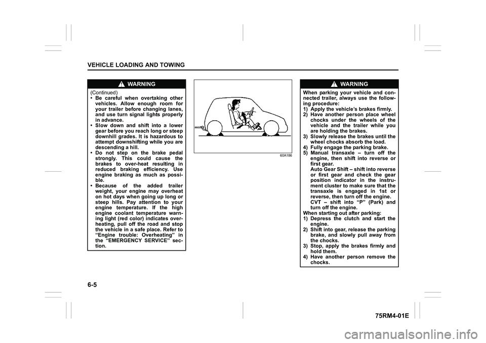
When parking your vehicle and con-
nected trailer, always use the follow-
ing procedure:
1) Apply the vehicle’s brakes firmly.
2) Have another person place wheel
chocks under the wheels of the
vehicle and the trailer while you
are holding the brakes.
3) Slowly release the brakes until the wheel chocks absorb the load.
4) Fully engage the parking brake.
5) Manual transaxle – turn off the engine, then shift into reverse or
first gear.
Auto Gear Shift – shift into reverse
or first gear and check the gear
position indicator in the instru-
ment cluster to make sure that the
transaxle is engaged in 1st or
reverse, then turn off the engine.
CVT – shift into “P” (Park) and
turn off the engine.
When starting out after parking:
1) Depress the clutch and start the engine.
2) Shift into gear, release the parking brake, and slowly pull away from
the chocks.
3) Stop, apply the brakes firmly and hold them.
4) Have another person remove the
chocks.
Page 350 of 505
7-1INSPECTION AND MAINTENANCE
75RM4-01E
60B128S
WA R N I N G
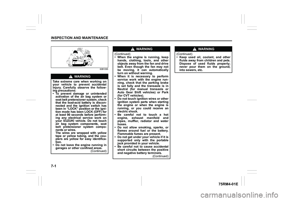
Take extreme care when working on
your vehicle to prevent accidental
injury. Carefully observe the follow-
ing precautions:
• To prevent damage or unintendedactivation of the air bag system or
seat belt pretensioner system, check
that the lead-acid battery is discon-
nected and the ignition switch has
been in “LOCK” position or the igni-
tion mode has been LOCK (OFF) for
at least 90 seconds before perform-
ing any electrical service work on
your SUZUKI vehicle. Do not touch
air bag system components, seat
belt pretensioner system compo-
nents or wires.
The wires are wrapped with yellow
tape or yellow tubing, and the cou-
plers are yellow for easy identifica-
tion.
• Do not leave the engine running in garages or other confined areas. (Continued)
WA R N I N G
(Continued)
• When the engine is running, keep
hands, clothing, tools, and other
objects away from the fan and drive
belt. Even though the fan may not
be moving, it can automatically
turn on without warning.
• When it is necessary to perform
service work with the engine run-
ning, check that the parking brake
is set fully and the transaxle is in
Neutral (for manual transaxle or
Auto Gear Shift vehicles) or Park
(for CVT vehicles).
• Do not touch ignition wires or other ignition system parts when starting
the engine or when the engine is
running, or you could receive an
electric shock.
•Be careful not to touch a hot engine, exhaust manifold and
pipes, muffler, radiator and water
hoses.
• Do not allow smoking, sparks, or flames around fuel or the battery.
Flammable fumes are present.
• Do not get under your vehicle if it is supported only with the portable
jack provided in your vehicle.
• Be careful not to cause accidental short circuits between the positive
and negative battery terminals. (Continued)
WA R N I N G
(Continued)
• Keep used oil, coolant, and other
fluids away from children and pets.
Dispose of used fluids properly;
never pour them on the ground,
into sewers, etc.
Page 353 of 505
7-4
INSPECTION AND MAINTENANCE
75RM4-01E
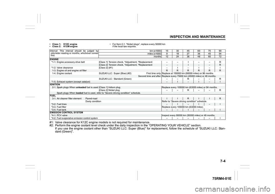
• Class 1: K12C engine
• Class 2: K12M engine• For Item 2-1. “Nickel plugs”, replace every 50000 km
if the local law requires.#1: Valve clearance for K12C engin e models is not required for maintenance.
#2: Perform the engine coolant l evel check under the daily inspection in the “OPERATING YOUR VEHICLE” section.
If you use the engine coolant other than “SUZUKI LLC: Super (Bl ue)” for replacement, follow the schedule of “SUZUKI LLC: Stan-
dard (Green)”.Interval: This interval should be judged by odometer reading or months, whichever comes
first. km (x1000) 15 30 45 60 75 90
miles (x1000) 9 18 27 36 45 54
months 12 24 36 48 60 72ENGINE*1-1. Engine accessory drive belt [Class 1] Tension check, *Adjust ment, *Replacement – – I – – R
[Class 2] Tension check, *Adjustment, *Replacement
–
–
I
–
–
R
*1-2. Valve clearance [Class 2] (#1) – I – I – I
1-3.
Engine oil and engine oil filter
R
R
R
R
R
R
1-4. Engine coolant SUZUKI LLC: Super (Blue) (#2)
First time only: Replace at 150000 km (90000 miles) or 96 months .
Second time and after:
Replace every 75000 km (45000 miles) or 48 months.
SUZUKI LLC: Standard (Green) – – R – – R
*1-5.
Exhaust system (except catalyst)
–
I
–
I
–
I
IGNITION
2-1.
Spark plugs When unleaded fuel is used
[Class 1] Iridium plug
Replace every 105000 km (63000 miles) or 84 months.
[Class 2] Nickel plug – – R – – R
Spark plugs When leaded fuel is used, refer to “Severe driving condition” schedule.
FUEL 3-1.
Air cleaner filter element
Paved-road
I
I
R
I
I
R
Dusty condition Refer to “Severe driving condition” schedule.
*3-2.
Fuel lines
–
I
–
I
–
I
*3-3. Fuel filter Replace every 105000 km (63000 miles).
*3-4.
Fuel tank
–
–
I
–
–
I
EMISSION CONTROL SYSTEM
*4-1.
PCV valve
Inspect every 80000 km (5 0000 miles) or 48 months.
*4-2.
Fuel evaporative emi ssion control system
––––– I
Page 354 of 505
7-5INSPECTION AND MAINTENANCE
75RM4-01E
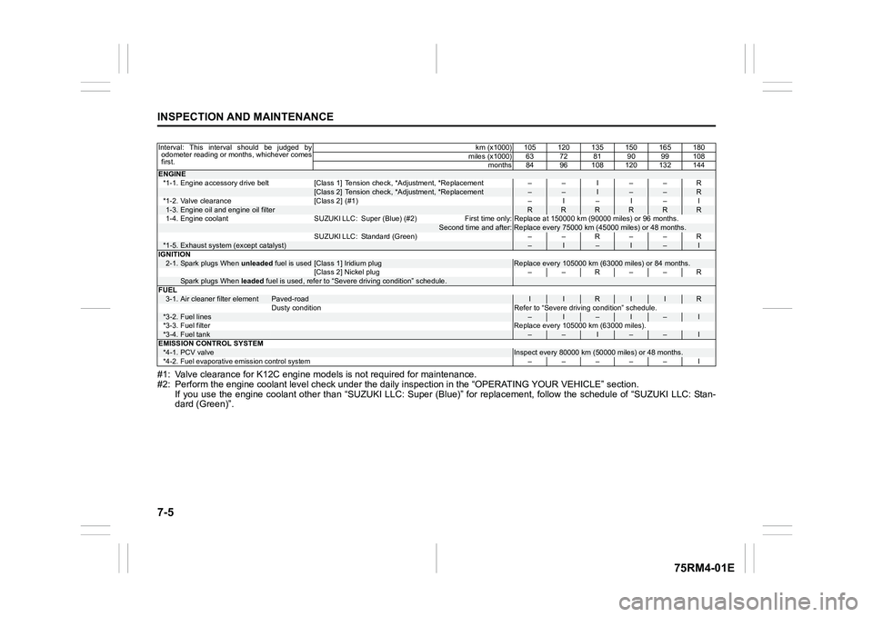
#1: Valve clearance for K12C engine models is not required for maintenance.
#2: Perform the engine coolant l evel check under the daily inspection in the “OPERATING YOUR VEHICLE” section.
If you use the engine coolant other than “SUZUKI LLC: Super (Bl ue)” for replacement, follow the schedule of “SUZUKI LLC: Stan-
dard (Green)”.Interval: This interval should be judged by odometer reading or months, whichever comes
first. km (x1000) 105 120 135 150 165 180
miles (x1000) 63 72 81 90 99 108 months 84 96 108 120 132 144ENGINE*1-1. Engine accessory drive belt [Class 1] Tension check, *Adjust ment, *Replacement – – I – – R
[Class 2] Tension check, *Adjustment, *Replacement
–
–
I
–
–
R
*1-2. Valve clearance [Class 2] (#1) – I – I – I
1-3.
Engine oil and engine oil filter
R
R
R
R
R
R
1-4. Engine coolant SUZUKI LLC: Super (Blue) (#2)
First time only: Replace at 150000 km (90000 miles) or 96 months .
Second time and after:
Replace every 75000 km (45000 miles) or 48 months.
SUZUKI LLC: Standard (Green) – – R – – R
*1-5.
Exhaust system (except catalyst)
–
I
–
I
–
I
IGNITION
2-1.
Spark plugs When unleaded fuel is used
[Class 1] Iridium plug
Replace every 105000 km (63000 miles) or 84 months.
[Class 2] Nickel plug – – R – – R
Spark plugs When leaded fuel is used, refer to “Severe driving condition” schedule.
FUEL 3-1.
Air cleaner filter element
Paved-road
I
I
R
I
I
R
Dusty condition Refer to “Severe driving condition” schedule.
*3-2.
Fuel lines
–
I
–
I
–
I
*3-3. Fuel filter Replace every 105000 km (63000 miles).
*3-4.
Fuel tank
–
–
I
–
–
I
EMISSION CONTROL SYSTEM
*4-1.
PCV valve
Inspect every 80000 km (5 0000 miles) or 48 months.
*4-2.
Fuel evaporative emi ssion control system
––––– I
Page 358 of 505
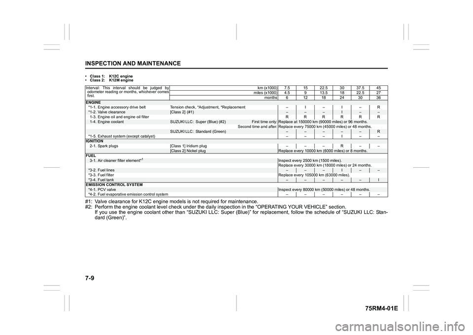
7-9INSPECTION AND MAINTENANCE
75RM4-01E
• Class 1: K12C engine
• Class 2: K12M engine#1: Valve clearance for K12C engine models is not required for maintenance.
#2: Perform the engine coolant l evel check under the daily inspection in the “OPERATING YOUR VEHICLE” section.
If you use the engine coolant other than “SUZUKI LLC: Super (Bl ue)” for replacement, follow the schedule of “SUZUKI LLC: Stan-
dard (Green)”.Interval: This interval should be judged by odometer reading or months, whichever comes
first. km (x1000) 7.5 15 22.5 30 37.5 45
miles (x1000) 4.5 9 13.5 18 22.5 27
months6 1218243036ENGINE*1-1. Engine accessory drive belt Tension check, *Adjustment, *Re placement – I – I – R*1-2.
Valve clearance
[Class 2] (#1)
–
–
–
I
–
–
1-3. Engine oil and engine oil filter RRRRRR
1-4.
Engine coolant
SUZUKI LLC:
Super (Blue) (#2)
First time only:
Replace at 150000 km (90000 miles) or 96 months.
Second time and after: Replace every 75000 km (45000 miles) or 48 months.
SUZUKI LLC:
Standard (Green)
–
–
–
–
–
R
*1-5. Exhaust system (except catalyst) ––– I ––
IGNITION
2-1. Spark plugs [Class 1] Iridium plug – – – R – –
[Class 2] Nickel plug
Replace every 10000 km (6000 miles) or 8 months.
FUEL
3-1.
Air cleaner filter element*
1
Inspect every 2500 km (1500 miles).
Replace every 30000 km (18000 miles) or 24 months.
*3-2.
Fuel lines
–
–
–
I
–
–
*3-3. Fuel filter Replace every 105000 km (63000 miles).
*3-4.
Fuel tank
–
–
–
–
–
I
EMISSION CONTROL SYSTEM
*4-1.
PCV valve
Inspect every 80000 km (5 0000 miles) or 48 months.
*4-2.
Fuel evaporative emi ssion control system
––––––