floor mat SUZUKI IGNIS 2022 Owners Manual
[x] Cancel search | Manufacturer: SUZUKI, Model Year: 2022, Model line: IGNIS, Model: SUZUKI IGNIS 2022Pages: 505, PDF Size: 8.36 MB
Page 35 of 505
2-12
BEFORE DRIVING
75RM4-01E
If the remote controller is left in the vehicle
and you lock the driver’s door or front pas-
senger’s door as described below, the door
will be automatically unlocked.
• If you open the driver’s door and lock thedoor by turning the lock knob forward or
pushing the power door locking switch,
the driver’s door will be automatically
unlocked.
• If you open the front passenger’s door and lock the door by turning the lock
knob forward or pushing the power door
locking switch, the front passenger’s
door will be automat ically unlocked.
NOTE:
• The reminder will not operate when the remote controller is on the instrument
panel, in the glove box, in a storage
compartment, in the sun visor or on the
floor, etc.
• Check that the driver always carries the remote controller.
• Do not leave the remote controller in the vehicle when leaving the vehicle. Battery replacement
If the remote controller becomes unreli-
able, replace the battery.
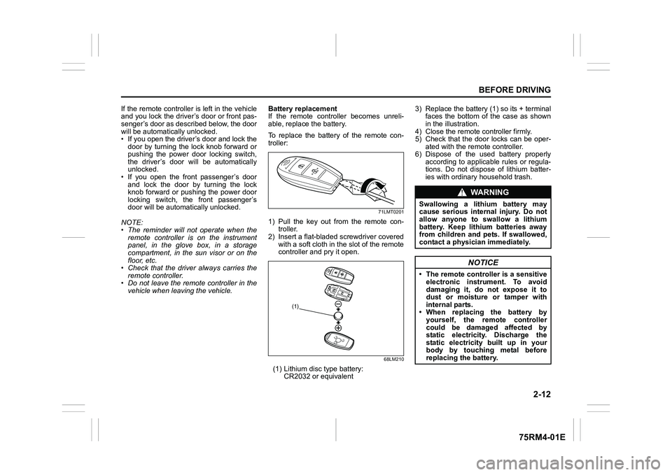
To replace the battery of the remote con-
troller:
71LMT0201
1) Pull the key out from the remote con-
troller.
2) Insert a flat-bladed screwdriver covered with a soft cloth in the slot of the remote
controller and pry it open.
68LM210
(1) Lithium disc type battery:
CR2032 or equivalent 3) Replace the battery (1) so its + terminal
faces the bottom of the case as shown
in the illustration.
4) Close the remote controller firmly.
5) Check that the door locks can be oper- ated with the remote controller.
6) Dispose of the used battery properly according to applicable rules or regula-
tions. Do not dispose of lithium batter-
ies with ordinary household trash.
(1)
WA R N I N G
Swallowing a lithium battery may
cause serious internal injury. Do not
allow anyone to swallow a lithium
battery. Keep lithium batteries away
from children and pets. If swallowed,
contact a physici an immediately.
NOTICE
• The remote controller is a sensitive
electronic instrument. To avoid
damaging it, do not expose it to
dust or moisture or tamper with
internal parts.
• When replacing the battery by yourself, the re mote controller
could be damaged affected by
static electricity. Discharge the
static electricity built up in your
body by touching metal before
replacing th e battery.
Page 88 of 505
2-65BEFORE DRIVING
75RM4-01E
Your vehicle is equipped with a diagnostic
module which records information about
the air bag system if the air bags deploy in
a crash. The module records information
about overall system status, and which
sensors activated the deployment.
Servicing the air bag system
If the air bags inflate, have the air bags
and related components replaced by an
authorized SUZUKI dealer as soon as pos-
sible.
If your vehicle ever gets in deep water and
the driver’s floor is submerged, the air bag
controller could be damaged. If this hap-
pens, ask your SUZUKI dealer to check
the air bag system as soon as possible.
Special procedures are required for servic-
ing or replacing an air bag. For that rea-
son, only an authorized SUZUKI dealer
should be allowed to service or replace
your air bags. Remind anyone who ser-
vices your SUZUKI vehicle that it has air
bags.
Service on or around air bag components
or wiring must be performed only by an
authorized SUZUKI dealer. Improper ser-
vice could result in unintended air bag
deployment or could render the air bag
inoperative. Either of these two conditions
may result in severe injury. To prevent damage or unintended inflation
of the air bag system, check that the lead-
acid battery is disconnected and the igni-
tion switch has been in “LOCK” position or
the ignition mode has been LOCK (OFF)
for at least 90 seconds before performing
any electrical service work on your
SUZUKI vehicle. Do not touch air bag sys-
tem components or wires. The wires are
wrapped with yellow tape or yellow tubing,
and the couplers are yellow for easy identi-
fication.
Scrapping a vehicle that has an uninflated
air bag can be hazardous. Ask your dealer,
body repair shop or scrap yard for help
with disposal.
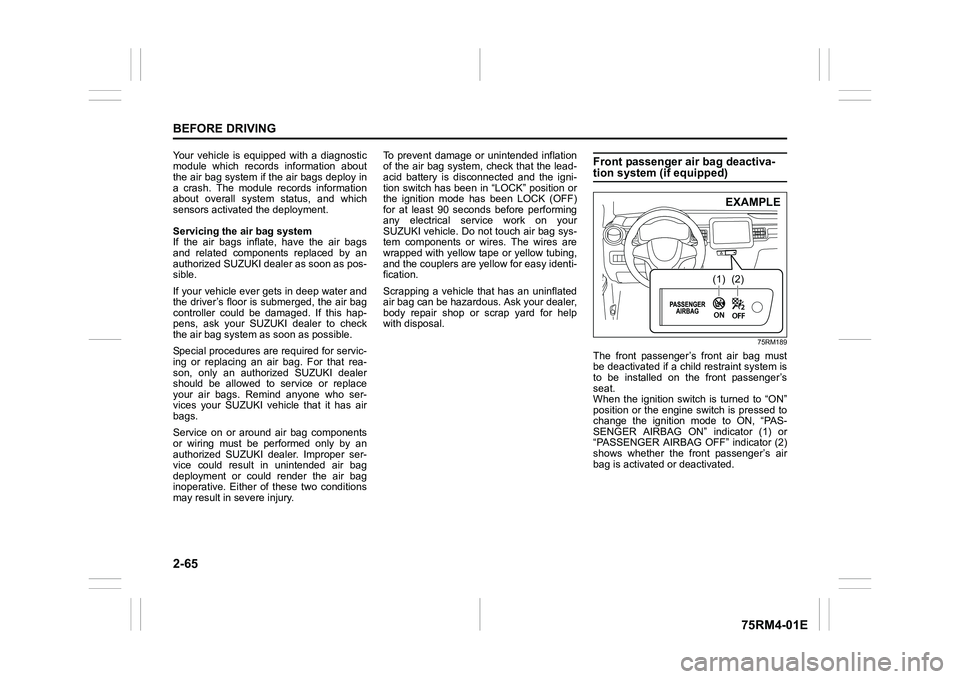
Front passenger air bag deactiva-tion system (if equipped)
75RM189
The front passenger’s front air bag must
be deactivated if a child restraint system is
to be installed on the front passenger’s
seat.
When the ignition switch is turned to “ON”
position or the engine switch is pressed to
change the ignition mode to ON, “PAS-
SENGER AIRBAG ON” indicator (1) or
“PASSENGER AIRBAG OFF” indicator (2)
shows whether the front passenger’s air
bag is activated or deactivated.
(1)
(2)EXAMPLE
Page 168 of 505
3-15OPERATING YOUR VEHICLE
75RM4-01E
• For Auto Gear Shift vehicles, if theengine cannot be started, make sure the
gearshift lever is in “N” before restarting
the engine.
• During the engine starting procedure, messages on the information display will
help you. Refer to “Information display” in
the “BEFORE DRIVING” section for
details.
• You should turn off such loads as the headlights and air co nditioning system to
facilitate starting of the engine.
• Even if you fail to start the engine, the starter motor will stop turning automati-
cally after a short time. After the starter
motor has stopped or if there is some
problem with the system, the starter
motor will rotate only while the engine
switch is being pressed.
Stopping engine• Depress the engine switch to stop theengine after the vehicle stopped com-
pletely.
• In case of emergency, you can stop the engine by quickly pushing the engine
switch more than 3 times, or pushing
and holding the engine switch for more
than 2 seconds while the vehicle is in
motion.
NOTE:
Except in cases of emergency, do not stop
the engine while the vehicle is in motion.
The steering and braking operation will
require more effort when the engine is
stopped.
Refer to “Braking” in this section.
• If the engine remains stopped for while after it was stopped unexpectedly or was
raced before stopping, a clicking sound
may be heard from around the engine
when it is restarted. This is not a mal-
function. Always let the engine idle
before stopping it.
Starting a cold and warm engineWith your foot taken off the accelerator
pedal, crank the engine by pressing the
engine switch to change the ignition mode
to START.
After pressing the engine switch to change
the ignition mode to START, the starter
cranks the engine for about 12 seconds
before it can start the engine. If the engine
fails to start at the first attempt, wait about
15 seconds, and then try again while keep-
ing the engine switch pressed while press-
ing down the accelerator pedal 1/3 of full
capacity. Release the accelerator pedal
when the engine starts.
If the engine still does not start, try holding
the accelerator pedal all the way to the
floor while cranking. This should clear the
engine if it is flooded.
If you are unable to start the engine using
this procedure, consult your SUZUKI
dealer.
NOTICE
If you stop the engine while the vehi-
cle is in motion, the CVT may be dam-
aged.
Avoid stopping the engine while driv-
ing.
NOTICE
Do not crank the engine for more
than 12 seconds at a time.
If the engine does not start on the
first try, wait abou t 15 seconds before
trying again.
Page 255 of 505
OTHER CONTROLS AND EQUIPMENT
5
75RM4-01E
60G407
OTHER CONTROLS AND EQUIPMENTFuel filler cap ....................................................................... 5-1
Engine hood ................................................... ..................... 5-2
Sun visor ..................................................... ......................... 5-4
Interior light ................................................ ......................... 5-5
Accessory socket .............. ....................... ........................... 5-6
AUX/USB socket (if equipped) . .......................................... 5-7
Assist grips (if equipped) .................................... ............... 5-7
Glove box ..................................................... ........................ 5-7
Cup holder and storage area ................................... .......... 5-8
Footrest ...................................................... .......................... 5-10
Floor mats .................................................... ........................ 5-10
Luggage compartment cover (if equipped) ...................... 5 -11
Roof rails (if equipped) ...................................... ................. 5-11
Frame hooks ................................................... ..................... 5-12
Heating and air conditioning system ........................... ..... 5-15
Heating system ................................................ .................... 5-17
Manual heating and a ir conditioning system ................... 5 -21
Automatic heating and ai r conditioning system
(climate control) ........... ....................................................... 5-26
Radio antenna ................................................. .................... 5-32
Installation of radi o frequency transmi tters ..................... 5-32
Audio system (Type A / Type B / Type C) (if equipped) ... 5-33
Page 265 of 505

5-10
OTHER CONTROLS AND EQUIPMENT
75RM4-01E
Footrest
75RM243
Use the footrest (1) as a support for your
left foot.
Floor mats
72M10201
To prevent the driver’s side floor mat from
sliding forward and possibly interfering with
the operation of the pedals, genuine
SUZUKI floor mats are recommended.
Whenever you put the driver’s side floor
mat back in the vehicle after it has been
removed, hook the floor mat grommets to
the fasteners and position the floor mat
properly in the footwell.
When you replace the floor mats in your
vehicle with a differ ent type such as all-
weather floor mats, we highly recommend
to use genuine SUZUKI floor mats for
proper fitting.
(1)
EXAMPLE
WA R N I N G
Failure to take the following precau-
tions may result in the driver’s side
floor mat interferin g with the pedals
and causing a loss of vehicle control
or an accident.
• Check that the floor mat grommets are hooked to the fasteners.
• Never place additional floor mats
on top of the existing floor mat.
Page 270 of 505
5-15OTHER CONTROLS AND EQUIPMENT
75RM4-01E
Heating and air conditioning systemThere are three types of heating and air
conditioning syst ems as follows:
• Heating system
• Manual heating and air conditioning sys- tem
• Automatic heating and air conditioning system (climate control)
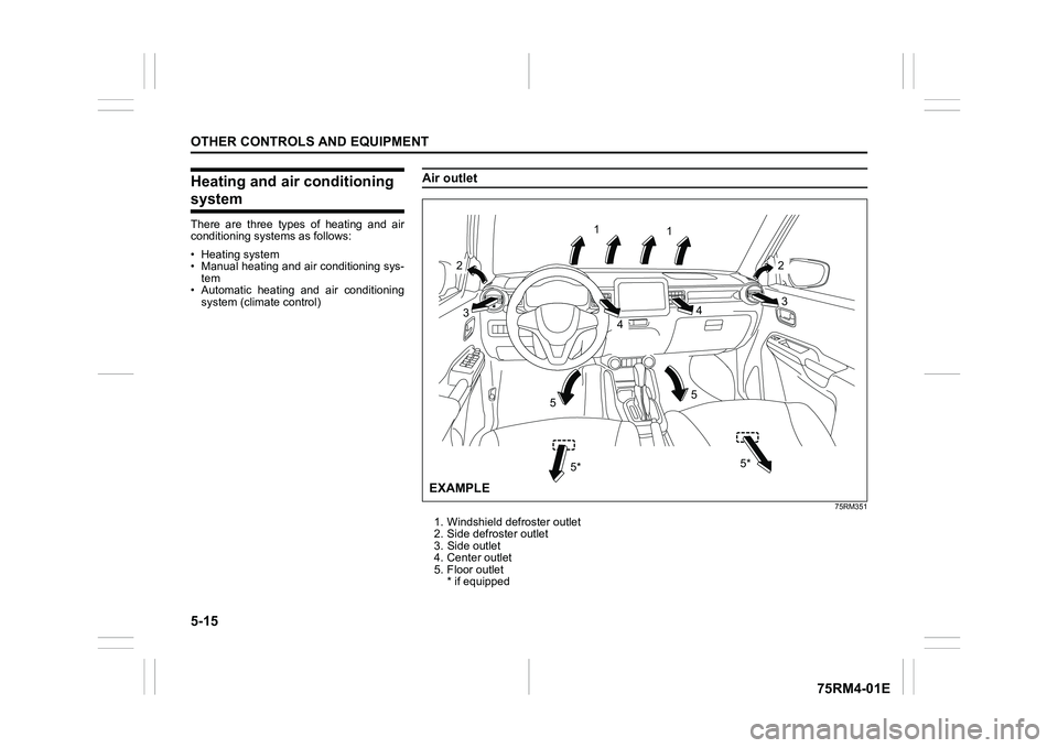
Air outlet
75RM351
1. Windshield defroster outlet
2. Side defroster outlet
3. Side outlet
4. Center outlet
5. Floor outlet * if equipped
1
2 1
2
3 3
4
4
5
5
5*
5*
EXAMPLE
Page 283 of 505
5-28
OTHER CONTROLS AND EQUIPMENT
75RM4-01E
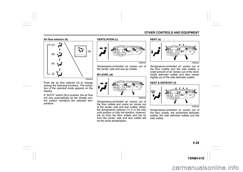
Air flow selector (4)
75RM029
Push the air flow selector (4) to change
among the following functions. The indica-
tion of the selected mode appears on the
display.
If “AUTO” switch (8) is pushed, the air flow
will vary automatically as the climate con-
trol system maintains the selected tem-
perature.VENTILATION (c)
75RM352
Temperature-controlled air comes out of
the center, side and rear air outlets.
BI-LEVEL (d)
75RM353
Temperature-controlled air comes out of
the floor outlets and cooler air comes out
of the center, side and rear outlets. When
the temperature selector (1) is in the fully
cold position or fully hot position, however,
the air from the floor outlets and the air
from the center, side and rear outlets will
be the same temperature.HEAT (e)
75RM354
Temperature-controlled air comes out of
the floor outlets and the side outlets, a
small amount of air comes out of the wind-
shield defroster outlets and also comes
slightly out of the side defroster outlets.
HEAT & DEFROST (f)
75RM358
Temperature-controlled air comes out of
the floor outlets, the windshield defroster
outlets, the side defroster outlets and the
side outlets.
(4)
(c)
(d)
(e)
(f)
Page 386 of 505
7-37INSPECTION AND MAINTENANCE
75RM4-01E
NOTE:
• The fluid level can be expected to gradu-ally fall as the brake pad and/or shoe
wear.
• Brake fluid absorbs water over time and
brake fluid with high water content may
cause vapor lock or brake system mal-
function.
Replace your brake fluid in accordance
with the maintenance schedule in your
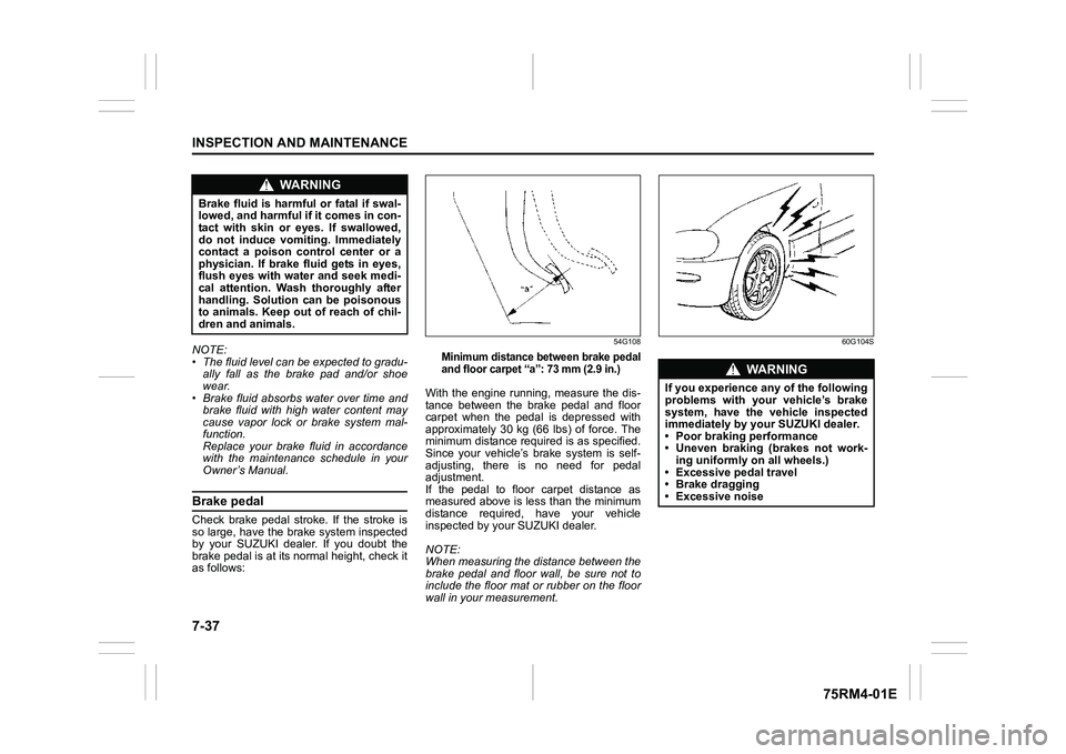
Owner’s Manual.Brake pedalCheck brake pedal stroke. If the stroke is
so large, have the brake system inspected
by your SUZUKI dealer. If you doubt the
brake pedal is at its normal height, check it
as follows:
54G108
Minimum distance between brake pedal
and floor carpet “a”: 73 mm (2.9 in.)
With the engine running, measure the dis-
tance between the brake pedal and floor
carpet when the pedal is depressed with
approximately 30 kg (66 lbs) of force. The
minimum distance required is as specified.
Since your vehicle’s brake system is self-
adjusting, there is no need for pedal
adjustment.
If the pedal to floor carpet distance as
measured above is less than the minimum
distance required, have your vehicle
inspected by your SUZUKI dealer.
NOTE:
When measuring the distance between the
brake pedal and floor wall, be sure not to
include the floor mat or rubber on the floor
wall in your measurement.
60G104S
WA R N I N G
Brake fluid is harmful or fatal if swal-
lowed, and harmful if it comes in con-
tact with skin or eyes. If swallowed,
do not induce vomiting. Immediately
contact a poison control center or a
physician. If brake fluid gets in eyes,
flush eyes with water and seek medi-
cal attention. Wash thoroughly after
handling. Solution can be poisonous
to animals. Keep out of reach of chil-
dren and animals.
WA R N I N G
If you experience any of the following
problems with your vehicle’s brake
system, have the vehicle inspected
immediately by your SUZUKI dealer.
• Poor braking performance
• Uneven braking (brakes not work- ing uniformly on all wheels.)
• Excessive pedal travel
• Brake dragging
• Excessive noise
Page 422 of 505
8-13EMERGENCY SERVICE
75RM4-01E
Engine trouble: Starter does not operate1) Try turning the ignition switch to“START” position or try pressing the
engine switch to change the ignition
mode to START with the headlights
turned on to determine the lead-acid
battery condition. If the headlights go
excessively dim or go off, it usually
means that either the lead-acid battery
is flat or the battery terminal contact is
poor. Recharge the lead-acid battery or
correct battery terminal contact as nec-
essary.
2) If the headlights remain bright, check the fuses. If the reas on for failure of the
starter is not obvious, there may be a
major electrical problem. Have the vehi-
cle inspected by your authorized
SUZUKI dealer.
Engine trouble: Flooded engine(Vehicle without keyless push start sys-
tem)
If the engine is flooded with gasoline, it
may be hard to start. If this happens, press
the accelerator pedal all the way to the
floor and hold it there while cranking the
engine.
• Do not operate the starter motor for more than 12 seconds.
(Vehicle with keyless push start system)
If the engine is flooded with gasoline, it
may be hard to start. If this happens, press
the accelerator pedal all the way to the
floor and hold it there while cranking the
engine.
• Do not operate the starter motor for more than 12 seconds.
NOTE:
If the engine refuses to start, the starter
motor automatically stops after a certain
period of time. After the starter motor has
automatically stopped or if there is any-
thing abnormal in the engine starting sys-
tem, the starter motor runs only while the
engine switch is held pressed.
Engine trouble: OverheatingThe engine could overheat temporarily
under severe driving conditions. If the high
engine coolant temperature warning light
comes on as overheating during driving:
1) Turn off the air conditioner, if equipped.
2) Take the vehicle to a safe place and park.
3) Let the engine run at the normal idle speed for a few minutes until the high
engine coolant temperature warning
light goes off.
WA R N I N G
If you see or hear escaping steam,
stop the vehicle in a safe place and
immediately turn off the engine to
cool it. Do not open the hood when
steam is present. When the steam
can no longer be seen or heard, open
the hood to see if the coolant is still
boiling. If it is, you must wait until it
stops boiling before you proceed.
Page 426 of 505
9-1APPEARANCE CARE
75RM4-01E
Corrosion preventionIt is important to take good care of your
vehicle to protect it from corrosion. Listed
below are instructions for how to maintain
your vehicle to prevent corrosion. Please
read and follow these instructions carefully.Important information about corro-sionCommon causes of corrosion
1) Accumulation of road salt, dirt, moisture or chemicals in hard-to-reach areas of
the vehicle und erbody or frame.
2) Chipping, scratches and any damage to treated or painted metal surfaces
resulting from minor accidents or abra-
sion by stones and gravel.
Environmental conditions which accel-
erate corrosion
1) Road salt, dust control chemicals, sea air or industrial pollution will all acceler-
ate the corrosion of metal.
2) High humidity will increase the rate of
corrosion particularly when the tem-
perature range is just above the freez-
ing point.
3) Moisture in certain areas of a vehicle for an extended period of time may pro-
mote corrosion even though other body
sections may be completely dry. 4) High temperatures will cause an accel-
erated rate of corrosion to parts of the
vehicle which are not well-ventilated to
permit quick drying.
This information illustrates the necessity of
keeping your vehicle (particularly the
underbody) as clean and dry as possible. It
is equally important to repair any damage
to the paint or protective coatings as soon
as possible.
How to help prevent corrosionWash your vehicle frequently
The best way to preserve the finish on your
vehicle and to help avoid corrosion is to
keep it clean with frequent washing.
Wash your vehicle at least once during the
winter and once immediately after the win-
ter. Keep your vehicle, particularly the
underside, as clean and dry as possible.
If you frequently drive on salted roads,
your vehicle should be washed at least
once a month during the winter. If you live
near the ocean, your vehicle should be
washed at least once a month throughout
the year.
For washing instructi ons, refer to “Vehicle
cleaning” section. Remove foreign ma
terial deposits
Foreign material such as salts, chemicals,
road oil or tar, tree sap, bird droppings and
industrial fall-out may damage the finish of
your vehicle if it is left on painted surfaces.
Remove these types of deposits as quickly
as possible. If these deposits are difficult to
wash off, an additional cleaner may be
required. Check that any cleaner you use
is not harmful to painted surfaces and is
specifically intended for your purposes.
Follow the manufacturer’s directions when
using these special cleaners.
Repair finish damage
Carefully examine your vehicle for damage
to the painted surfaces. Should you find
any chips or scratches in the paint, touch
them up immediately to prevent corrosion
from starting. If the chips or scratches have
gone through to the bare metal, have a
qualified body shop make the repair.
Keep passenger and luggage compart-
ments clean
Moisture, dirt or mud can accumulate
under the floor mats and may cause corro-
sion. Occasionally, check under these
mats to ensure that this area is clean and
dry. More frequent checks are necessary if
the vehicle is used for off-road driving or in
wet weather.
Certain cargos such as chemicals, fertiliz-
ers, cleaners, salts, etc. are extremely cor-
rosive by nature. These products should
be transported in sealed containers. If they