Brake SUZUKI JIMNY 2005 3.G Service Owners Manual
[x] Cancel search | Manufacturer: SUZUKI, Model Year: 2005, Model line: JIMNY, Model: SUZUKI JIMNY 2005 3.GPages: 687, PDF Size: 13.38 MB
Page 308 of 687

Downloaded from www.Manualslib.com manuals search engine BRAKES 5-47
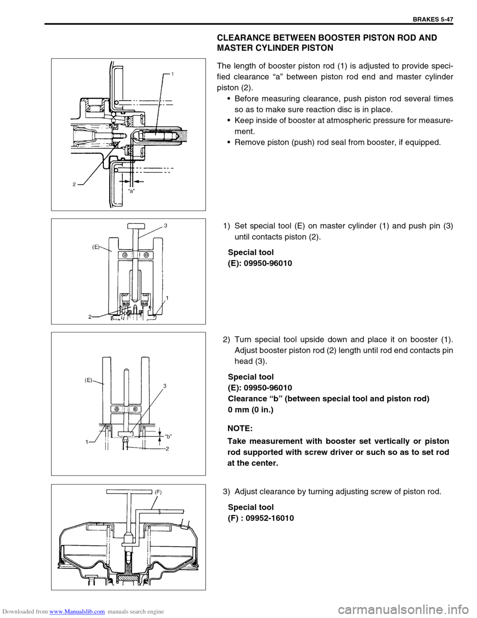
CLEARANCE BETWEEN BOOSTER PISTON ROD AND
MASTER CYLINDER PISTON
The length of booster piston rod (1) is adjusted to provide speci-
fied clearance “a” between piston rod end and master cylinder
piston (2).
Before measuring clearance, push piston rod several times
so as to make sure reaction disc is in place.
Keep inside of booster at atmospheric pressure for measure-
ment.
Remove piston (push) rod seal from booster, if equipped.
1) Set special tool (E) on master cylinder (1) and push pin (3)
until contacts piston (2).
Special tool
(E): 09950-96010
2) Turn special tool upside down and place it on booster (1).
Adjust booster piston rod (2) length until rod end contacts pin
head (3).
Special tool
(E): 09950-96010
Clearance “b” (between special tool and piston rod)
0 mm (0 in.)
3) Adjust clearance by turning adjusting screw of piston rod.
Special tool
(F) : 09952-16010
NOTE:
Take measurement with booster set vertically or piston
rod supported with screw driver or such so as to set rod
at the center.
Page 309 of 687
![SUZUKI JIMNY 2005 3.G Service Owners Manual Downloaded from www.Manualslib.com manuals search engine 5-48 BRAKES
Brake Hose/Pipe
Front brake hose/pipe
For left-hand steering vehicle
[A] : For vehicle without ABS X : View X 5. Brake caliper 12. SUZUKI JIMNY 2005 3.G Service Owners Manual Downloaded from www.Manualslib.com manuals search engine 5-48 BRAKES
Brake Hose/Pipe
Front brake hose/pipe
For left-hand steering vehicle
[A] : For vehicle without ABS X : View X 5. Brake caliper 12.](/img/20/7588/w960_7588-308.png)
Downloaded from www.Manualslib.com manuals search engine 5-48 BRAKES
Brake Hose/Pipe
Front brake hose/pipe
For left-hand steering vehicle
[A] : For vehicle without ABS X : View X 5. Brake caliper 12. To front left brake caliper
[B] : For vehicle with ABS Y : View Y 6. 4 way joint 13. To rear brake
F : Front side Z : View Z 7. 5 way joint a-d: Clamp
R : Right side 1. E-ring 8. ABS hydraulic unit/control mod-
ule assemblyTightening torque
T : Top side 2. Flexible hose 9. P valve
V : View V 3. Hose washer 10. Hose bracket
W : View W 4. Hose bolt 11. To front right brake caliper
Page 310 of 687
![SUZUKI JIMNY 2005 3.G Service Owners Manual Downloaded from www.Manualslib.com manuals search engine BRAKES 5-49
For right-hand steering vehicle
[A] : For vehicle without ABS X : View X 5. Brake caliper 12. To front left brake caliper
[B] : For SUZUKI JIMNY 2005 3.G Service Owners Manual Downloaded from www.Manualslib.com manuals search engine BRAKES 5-49
For right-hand steering vehicle
[A] : For vehicle without ABS X : View X 5. Brake caliper 12. To front left brake caliper
[B] : For](/img/20/7588/w960_7588-309.png)
Downloaded from www.Manualslib.com manuals search engine BRAKES 5-49
For right-hand steering vehicle
[A] : For vehicle without ABS X : View X 5. Brake caliper 12. To front left brake caliper
[B] : For vehicle with ABS Y : View Y 6. 4 way joint 13. To rear brake
F : Front side Z : View Z 7. 5 way joint 14. Front brake master cylinder
R : Right side 1. E-ring 8. ABS hydraulic unit a-f: Clamp
T : Top side 2. Flexible hose 9. P valve Tightening torque
V : View V 3. Hose washer 10. Hose bracket
W : View W 4. Hose bolt 11. To front right brake caliper
Page 311 of 687

Downloaded from www.Manualslib.com manuals search engine 5-50 BRAKES
REMOVAL
1) Raise, suitably support vehicle. Remove wheel if necessary.
2) Clean dirt and foreign material from both hose end or pipe end fittings. Remove brake hose and pipe.
INSTALLATION
1) Install brake hose and pipe by reversing removal procedure, noting the following points.
For installation, make sure that steering wheel is in straightforward position and hose has no twist or kink.
Check to make sure that hose doesn’t contact any part of suspension, both in extreme right and extreme left
turn conditions. If it does at any point, remove and correct. Fill and maintain brake fluid level in reservoir.
Bleed brake system.
2) Perform brake test and check installed part for fluid leakage.
Page 312 of 687

Downloaded from www.Manualslib.com manuals search engine BRAKES 5-51
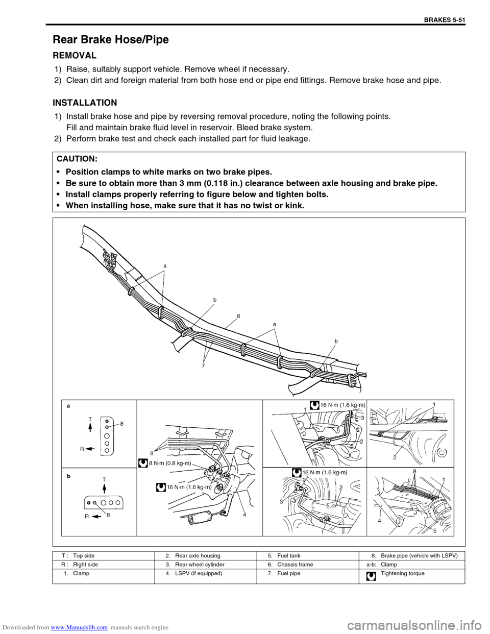
Rear Brake Hose/Pipe
REMOVAL
1) Raise, suitably support vehicle. Remove wheel if necessary.
2) Clean dirt and foreign material from both hose end or pipe end fittings. Remove brake hose and pipe.
INSTALLATION
1) Install brake hose and pipe by reversing removal procedure, noting the following points.
Fill and maintain brake fluid level in reservoir. Bleed brake system.
2) Perform brake test and check each installed part for fluid leakage.
CAUTION:
Position clamps to white marks on two brake pipes.
Be sure to obtain more than 3 mm (0.118 in.) clearance between axle housing and brake pipe.
Install clamps properly referring to figure below and tighten bolts.
When installing hose, make sure that it has no twist or kink.
T : Top side 2. Rear axle housing 5. Fuel tank 8. Brake pipe (vehicle with LSPV)
R : Right side 3. Rear wheel cylinder 6. Chassis frame a-b: Clamp
1. Clamp 4. LSPV (if equipped) 7. Fuel pipe Tightening torque
Page 313 of 687

Downloaded from www.Manualslib.com manuals search engine 5-52 BRAKES
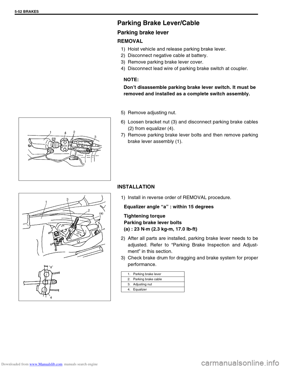
Parking Brake Lever/Cable
Parking brake lever
REMOVAL
1) Hoist vehicle and release parking brake lever.
2) Disconnect negative cable at battery.
3) Remove parking brake lever cover.
4) Disconnect lead wire of parking brake switch at coupler.
5) Remove adjusting nut.
6) Loosen bracket nut (3) and disconnect parking brake cables
(2) from equalizer (4).
7) Remove parking brake lever bolts and then remove parking
brake lever assembly (1).
INSTALLATION
1) Install in reverse order of REMOVAL procedure.
Equalizer angle “a” : within 15 degrees
Tightening torque
Parking brake lever bolts
(a) : 23 N·m (2.3 kg-m, 17.0 lb-ft)
2) After all parts are installed, parking brake lever needs to be
adjusted. Refer to “Parking Brake Inspection and Adjust-
ment” in this section.
3) Check brake drum for dragging and brake system for proper
performance. NOTE:
Don’t disassemble parking brake lever switch. It must be
removed and installed as a complete switch assembly.
1. Parking brake lever
2. Parking brake cable
3. Adjusting nut
4. Equalizer
Page 314 of 687

Downloaded from www.Manualslib.com manuals search engine BRAKES 5-53
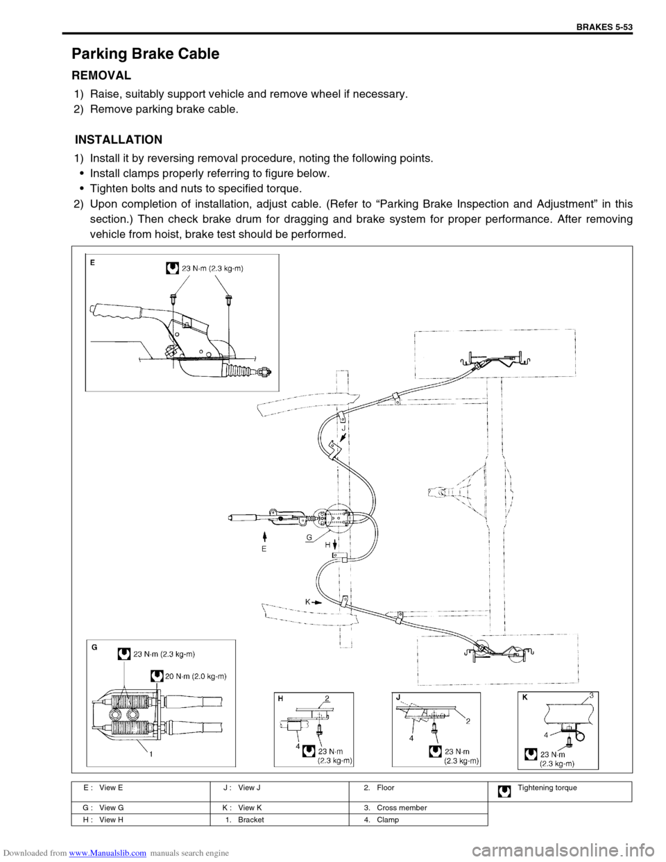
Parking Brake Cable
REMOVAL
1) Raise, suitably support vehicle and remove wheel if necessary.
2) Remove parking brake cable.
INSTALLATION
1) Install it by reversing removal procedure, noting the following points.
Install clamps properly referring to figure below.
Tighten bolts and nuts to specified torque.
2) Upon completion of installation, adjust cable. (Refer to “Parking Brake Inspection and Adjustment” in this
section.) Then check brake drum for dragging and brake system for proper performance. After removing
vehicle from hoist, brake test should be performed.
E : View E J : View J 2. Floor Tightening torque
G : View G K : View K 3. Cross member
H : View H 1. Bracket 4. Clamp
Page 315 of 687

Downloaded from www.Manualslib.com manuals search engine 5-54 BRAKES
Tightening Torque Specifications
Required Service Material
Fastening partTightening torque
Nm kg-m lb-ft
Brake caliper carrier bolt 85 8.5 61.5
Brake caliper pin bolt 22 2.2 16.0
Front brake flexible hose bolt 23 2.3 17.0
Rear brake back plate nut 23 2.3 17.0
Master cylinder nut 13 1.3 9.5
Booster nut 13 1.3 9.5
Brake pipe 5-way 4-way joint bolt 11 1.1 8.0
Brake pipe flare nut 16 1.6 12.0
LSPV bolt/P valve bolt 25 2.5 18.0
Brake bleeder plugFront caliper 11 1.1 8.0
Rear wheel cylinder, LSPV 8 0.8 6.0
Wheel nut 95 9.5 69.0
Hose bracket bolt 11 1.1 8.0
Booster clevis nut 25 2.5 18.0
Stop light switch lock nut 6.5 0.65 4.7
Parking brake lever bolt 23 2.3 17.0
Wheel cylinder mounting bolt 9 0.9 6.5
Piston stopper bolt 10 1.0 7.5
LSPV adjust bolt 25 2.5 18.0
Material Recommended SUZUKI products Use
Brake fluid Indicated on reservoir tank cap or
described in owner’s manual of vehi-
cleTo fill master cylinder reservoir.
To clean and apply to inner parts of master
cylinder caliper and wheel cylinder when they
are disassembled.
Water tight sealant SEALING COMPOUND 366E
99000-31090To apply to mating surfaces of brake back
plate and rear wheel cylinder.
Sealant SUZUKI BOND NO. 1215
99000-31110To apply to mating surfaces of brake back
plate and rear axle housing.
To apply to mating surfaces of brake back
plate and rear wheel bearing retainer.
Page 316 of 687

Downloaded from www.Manualslib.com manuals search engine BRAKES 5-55
Special Tool
09900-20205 09900-20602 09900-20701 09956-02210
Micrometer (0 – 25 mm) Dial gauge (1/1000 mm) Magnetic stand Brake circuit plug
09922-85811 09942-15510 09943-35511 09950-78220
Connector pin remover Sliding hammer Brake drum remover
(Front wheel hub
remover)Flare nut wrench (10 mm)
09950-96010 09952-16010 09956-02310
Booster piston rod gauge Booster piston rod
adjusterFluid pressure gauge
Page 317 of 687

Downloaded from www.Manualslib.com manuals search engine 5-56 BRAKES