crank SUZUKI JIMNY 2005 3.G Service Owners Manual
[x] Cancel search | Manufacturer: SUZUKI, Model Year: 2005, Model line: JIMNY, Model: SUZUKI JIMNY 2005 3.GPages: 687, PDF Size: 13.38 MB
Page 662 of 687
Downloaded from www.Manualslib.com manuals search engine CRANKING SYSTEM 6G-3
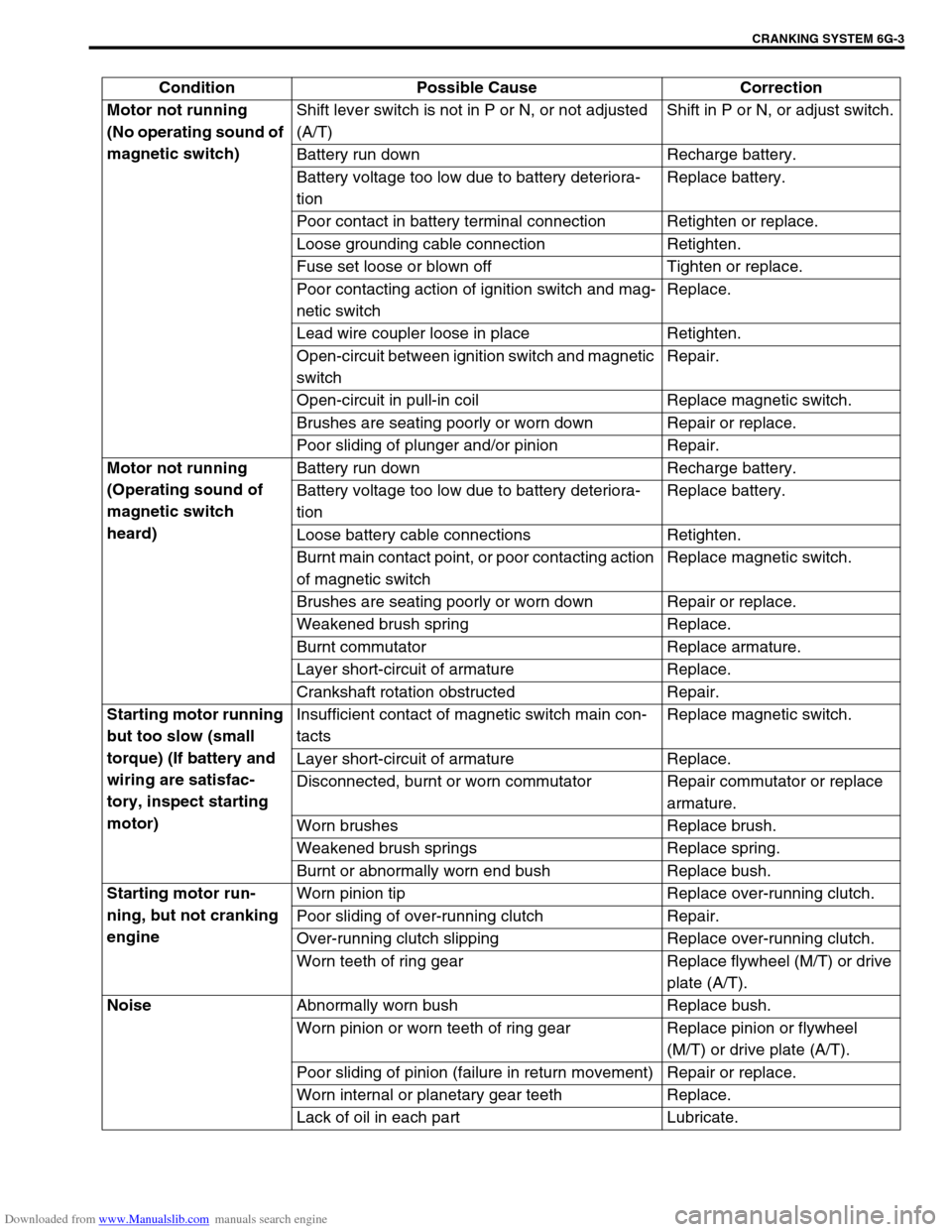
Condition Possible Cause Correction
Motor not running
(No operating sound of
magnetic switch)Shift lever switch is not in P or N, or not adjusted
(A/T)Shift in P or N, or adjust switch.
Battery run down Recharge battery.
Battery voltage too low due to battery deteriora-
tionReplace battery.
Poor contact in battery terminal connection Retighten or replace.
Loose grounding cable connection Retighten.
Fuse set loose or blown off Tighten or replace.
Poor contacting action of ignition switch and mag-
netic switchReplace.
Lead wire coupler loose in place Retighten.
Open-circuit between ignition switch and magnetic
switchRepair.
Open-circuit in pull-in coil Replace magnetic switch.
Brushes are seating poorly or worn down Repair or replace.
Poor sliding of plunger and/or pinion Repair.
Motor not running
(Operating sound of
magnetic switch
heard)Battery run down Recharge battery.
Battery voltage too low due to battery deteriora-
tionReplace battery.
Loose battery cable connections Retighten.
Burnt main contact point, or poor contacting action
of magnetic switchReplace magnetic switch.
Brushes are seating poorly or worn down Repair or replace.
Weakened brush spring Replace.
Burnt commutator Replace armature.
Layer short-circuit of armature Replace.
Crankshaft rotation obstructed Repair.
Starting motor running
but too slow (small
torque) (If battery and
wiring are satisfac-
tory, inspect starting
motor)Insufficient contact of magnetic switch main con-
tactsReplace magnetic switch.
Layer short-circuit of armature Replace.
Disconnected, burnt or worn commutator Repair commutator or replace
armature.
Worn brushes Replace brush.
Weakened brush springs Replace spring.
Burnt or abnormally worn end bush Replace bush.
Starting motor run-
ning, but not cranking
engineWorn pinion tip Replace over-running clutch.
Poor sliding of over-running clutch Repair.
Over-running clutch slipping Replace over-running clutch.
Worn teeth of ring gear Replace flywheel (M/T) or drive
plate (A/T).
Noise
Abnormally worn bush Replace bush.
Worn pinion or worn teeth of ring gear Replace pinion or flywheel
(M/T) or drive plate (A/T).
Poor sliding of pinion (failure in return movement) Repair or replace.
Worn internal or planetary gear teeth Replace.
Lack of oil in each part Lubricate.
Page 663 of 687
Downloaded from www.Manualslib.com manuals search engine 6G-4 CRANKING SYSTEM
Performance Test
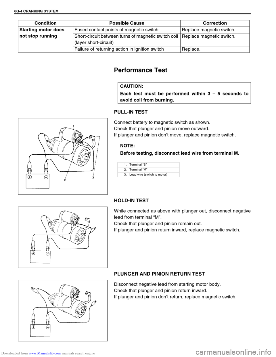
PULL-IN TEST
Connect battery to magnetic switch as shown.
Check that plunger and pinion move outward.
If plunger and pinion don’t move, replace magnetic switch.
HOLD-IN TEST
While connected as above with plunger out, disconnect negative
lead from terminal “M”.
Check that plunger and pinion remain out.
If plunger and pinion return inward, replace magnetic switch.
PLUNGER AND PINION RETURN TEST
Disconnect negative lead from starting motor body.
Check that plunger and pinion return inward.
If plunger and pinion don’t return, replace magnetic switch. Starting motor does
not stop runningFused contact points of magnetic switch Replace magnetic switch.
Short-circuit between turns of magnetic switch coil
(layer short-circuit)Replace magnetic switch.
Failure of returning action in ignition switch Replace.
CAUTION:
Each test must be performed within 3 – 5 seconds to
avoid coil from burning.
NOTE:
Before testing, disconnect lead wire from terminal M.
1. Terminal “S”
2. Terminal “M”
3. Lead wire (switch to motor)
Condition Possible Cause Correction
Page 664 of 687
Downloaded from www.Manualslib.com manuals search engine CRANKING SYSTEM 6G-5
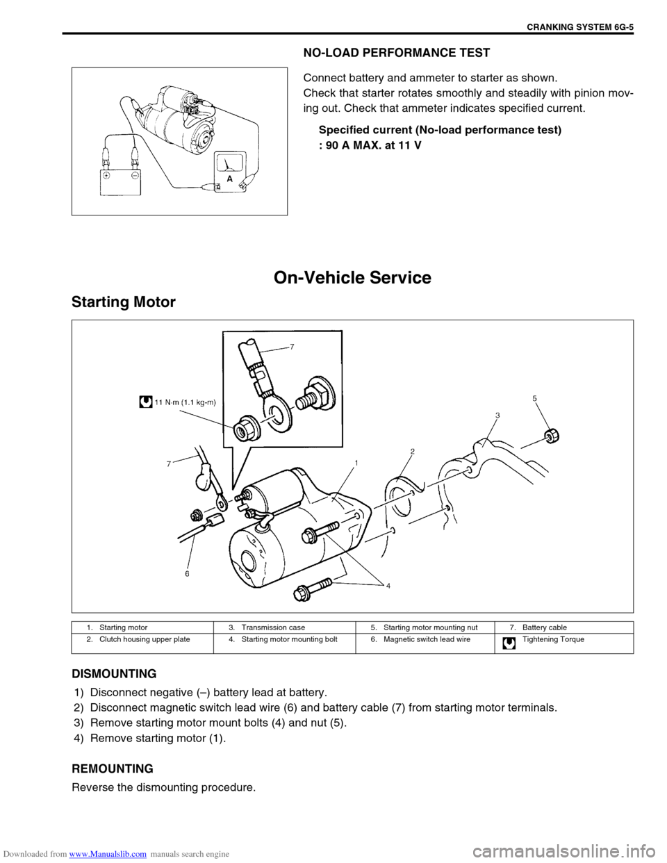
NO-LOAD PERFORMANCE TEST
Connect battery and ammeter to starter as shown.
Check that starter rotates smoothly and steadily with pinion mov-
ing out. Check that ammeter indicates specified current.
Specified current (No-load performance test)
: 90 A MAX. at 11 V
On-Vehicle Service
Starting Motor
DISMOUNTING
1) Disconnect negative (–) battery lead at battery.
2) Disconnect magnetic switch lead wire (6) and battery cable (7) from starting motor terminals.
3) Remove starting motor mount bolts (4) and nut (5).
4) Remove starting motor (1).
REMOUNTING
Reverse the dismounting procedure.
1. Starting motor 3. Transmission case 5. Starting motor mounting nut 7. Battery cable
2. Clutch housing upper plate 4. Starting motor mounting bolt 6. Magnetic switch lead wire Tightening Torque
Page 665 of 687

Downloaded from www.Manualslib.com manuals search engine 6G-6 CRANKING SYSTEM
DISASSEMBLY AND REASSEMBLY
NOTE:
Make sure to apply grease before assembly, where are indicated “A” in the figure below.
Spare parts have been lubricated.
1. Front housing 6. Over-running clutch 11. Magnetic switch 16. Packing 21. Rear bracket
2. Bush 7. Lever 12. Ball 17. Yoke 22. Rear bush
3. Snap ring 8. Plunger 13. Internal gear 18. Armature 23. Brush spring
4. Pinion stop ring 9. Plate 14. Planetary carrier shaft 19. Brush Apply grease (99000-25010)
5. Pinion gear 10. Seal rubber 15. Planetary gear 20. Brush holder Do not reuse.
Page 666 of 687

Downloaded from www.Manualslib.com manuals search engine CRANKING SYSTEM 6G-7
Specifications
Voltage 12 volts
Output 0.9 kW 1.2 kW
Rating 30 seconds
Direction of rotation Clockwise as viewed from pinion side
Brush length 12.3 mm (0.48 in.) 12.3 mm (0.48 in.)
Number of pinion teeth 8
Performance Condition Guarantee
Around at
20° C (68 °F)No load characteristic 11.0 V90 A maximum
2,800 rpm minimum90 A maximum
2,500 rpm minimum
Load characteristic8.0 V
200 A4.8 N·m (0.48 kg-m,
3.5 lb-ft) minimum
1,260 rpm minimum–
7.5 V
300 A–10.5 N·m (1.05 kg-m,
7.6 lb-ft) minimum
880 rpm minimum
Locked rotor current3.5 V550 A maximum
12.2 N·m (1.22 kg-m,
8.8 lb-ft) minimum–
4.0 V–760 A maximum
19.5 N·m (1.95 kg-m,
14.1 lb-ft) minimum
Magnetic switch operating voltage 8 volts maximum
Page 667 of 687

Downloaded from www.Manualslib.com manuals search engine 6G-8 CRANKING SYSTEM
Page 669 of 687
Downloaded from www.Manualslib.com manuals search engine 6H-2 CHARGING SYSTEM
General Description
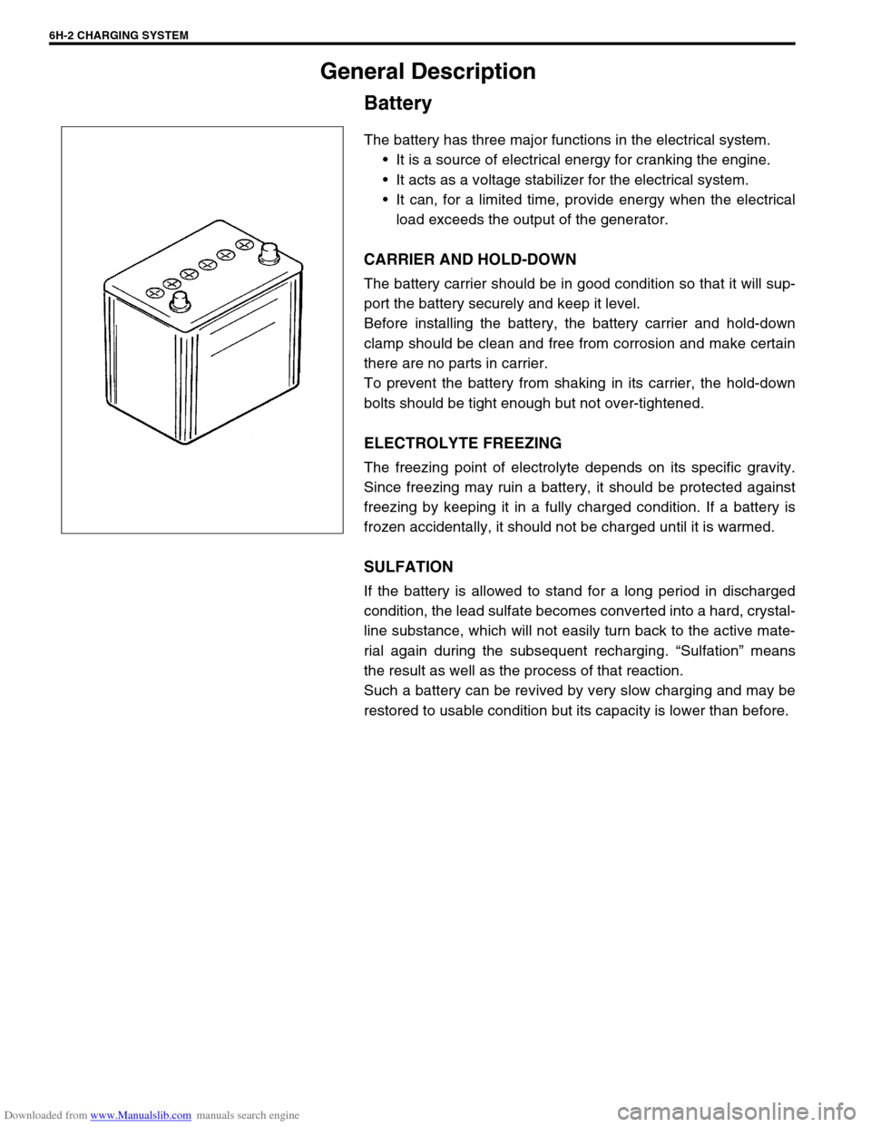
Battery
The battery has three major functions in the electrical system.
It is a source of electrical energy for cranking the engine.
It acts as a voltage stabilizer for the electrical system.
It can, for a limited time, provide energy when the electrical
load exceeds the output of the generator.
CARRIER AND HOLD-DOWN
The battery carrier should be in good condition so that it will sup-
port the battery securely and keep it level.
Before installing the battery, the battery carrier and hold-down
clamp should be clean and free from corrosion and make certain
there are no parts in carrier.
To prevent the battery from shaking in its carrier, the hold-down
bolts should be tight enough but not over-tightened.
ELECTROLYTE FREEZING
The freezing point of electrolyte depends on its specific gravity.
Since freezing may ruin a battery, it should be protected against
freezing by keeping it in a fully charged condition. If a battery is
frozen accidentally, it should not be charged until it is warmed.
SULFATION
If the battery is allowed to stand for a long period in discharged
condition, the lead sulfate becomes converted into a hard, crystal-
line substance, which will not easily turn back to the active mate-
rial again during the subsequent recharging. “Sulfation” means
the result as well as the process of that reaction.
Such a battery can be revived by very slow charging and may be
restored to usable condition but its capacity is lower than before.
Page 670 of 687

Downloaded from www.Manualslib.com manuals search engine CHARGING SYSTEM 6H-3
BUILT-IN INDICATOR (IF EQUIPPED)
The battery has a built-in temperature compensated indicator in
the top of the battery. This indicator is to be used with the follow-
ing diagnostic procedure. When checking the indicator, make
sure that the battery has a clean top. A light may be needed in
some poorly-lit areas.
Three types of indication which is available under normal opera-
tion are as follows.
Green Dot
Battery is sufficiently charged for testing.
Dark
Battery must be charged before testing.
If there is a cranking complaint, battery should be tested as
described in Diagnosis section. Charging and electrical sys-
tems should also be checked at this time.
Clear or Light Yellow
This means that fluid level is below the bottom of hydrome-
ter. Its possible cause is excessive or prolonged charging, a
broken case, excessive tipping or normal battery deteriora-
tion.
When the battery is found in such condition, it is possible
that high charging voltage is caused by the faulty charging
system and therefore, charging and electrical systems need
to be checked. If there is a trouble in cranking and its cause
lies in the battery, it should be replaced.
CARE OF BATTERY
1) The battery is a very reliable component, but needs periodi-
cal attentions.
Keep the battery carrier clean.
Prevent rust formation on the terminal posts.
Keep the electrolyte up to the upper level uniformly in all
cells. WARNING:
Never expose battery to open flame or electric spark
because of battery generate gas which is flammable
and explosive.
Do not allow battery fluid to contact eyes, skin, fabrics,
or painted surfaces as fluid is a corrosive acid. Flush
any contacted area with water immediately and thor-
oughly.
Batteries should always be kept out of reach of chil-
dren.
Page 674 of 687
Downloaded from www.Manualslib.com manuals search engine CHARGING SYSTEM 6H-7
How to use the temperature-corrected state-of-charge
graph
Suppose your S.G. reading is 1.28 and the battery temperature is
–5 °C (23 °F). Locate the intersection of the –5 °C line and the
1.28 S.G. line.
The intersection is within the “A” zone (shaded area in the graph)
and that means CHARGED STATE.
To know how much the battery is charged, draw a line parallel to
the zone demarcation line and extend it to the right till it meets
with the percentage scale. In the present example, the line meets
at about 85% point on the percentage scale. Therefore, the bat-
tery is charged up to the 85% level.
Generator
Trouble in charging system will show up as one or more of follow-
ing conditions:
1) Faulty indicator lamp operation.
2) An undercharged battery as evidenced by slow cranking or
indicator dark.
3) An overcharged battery as evidenced by excessive spewing
of electrolyte from vents.
Noise from generator may be caused by a loose drive pulley,
loose mounting bolts, worn or dirty bearings, defective diode, or
defective stator.
FAULTY INDICATOR LAMP OPERATION
CAUTION:
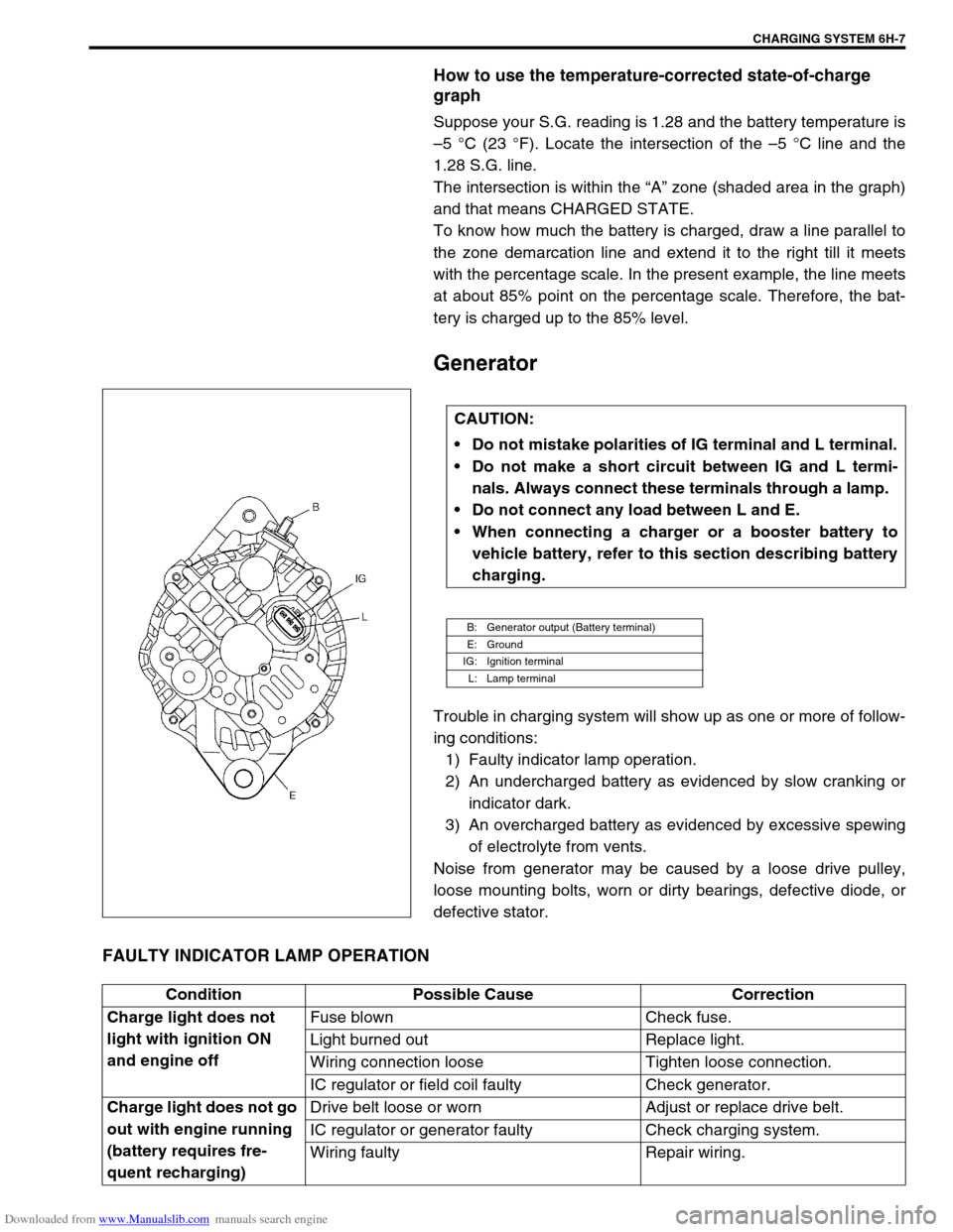
Do not mistake polarities of IG terminal and L terminal.
Do not make a short circuit between IG and L termi-
nals. Always connect these terminals through a lamp.
Do not connect any load between L and E.
When connecting a charger or a booster battery to
vehicle battery, refer to this section describing battery
charging.
B: Generator output (Battery terminal)
E: Ground
IG: Ignition terminal
L: Lamp terminal
Condition Possible Cause Correction
Charge light does not
light with ignition ON
and engine offFuse blown Check fuse.
Light burned out Replace light.
Wiring connection loose Tighten loose connection.
IC regulator or field coil faulty Check generator.
Charge light does not go
out with engine running
(battery requires fre-
quent recharging)Drive belt loose or worn Adjust or replace drive belt.
IC regulator or generator faulty Check charging system.
Wiring faulty Repair wiring.
Page 675 of 687

Downloaded from www.Manualslib.com manuals search engine 6H-8 CHARGING SYSTEM
UNDERCHARGED BATTERY
This condition, as evidenced by slow cranking or indicator clear
with red dot can be caused by one or more of the following condi-
tions even though indicator lamp may be operating normal.
Following procedure also applies to cars with voltmeter and
ammeter.
1) Make sure that undercharged condition has not been caused
by accessories left on for extended period of time.
2) Check drive belt for proper tension.
3) If battery defect is suspected, refer to BATTERY section.
4) Inspect wiring for defects. Check all connections for tight-
ness and cleanliness, battery cable connections at battery,
starting motor and ignition ground cable.
5) Connect voltmeter and ammeter as shown in the figure.
6) Measure current and voltage.
No-load Check
1) Run engine from idling up to 2,000 rpm and read meters.
Standard current
10 A maximum
Standard voltage
14.4 – 15.0 V (at 20 °C, 68 °F)
Higher Voltage
If voltage is higher than standard value, check ground of brushes.
If brushes are not grounded, replace IC regulator.
Lower Voltage
If voltage is below or in standard value, increase engine speed up
to 2,000 – 2,500 rpm soon after starting engine, and read maxi-
mum value on ammeter immediately.
If current is less than 49 A, repair or replace generator.NOTE:
Use fully charged battery.
1. Generator
2. Ammeter (between generator (B) terminal and battery (+) terminal)
3. Voltmeter (between generator (B) terminal and ground)
4. Battery
5. Load
6. Switch
NOTE:
Turn off switches of all accessories (wiper, heater etc.).
NOTE:
Consideration should be taken that voltage will differ
somewhat with regulator case temperature as shown in
the graph.