front SUZUKI JIMNY 2005 3.G Service Workshop Manual
[x] Cancel search | Manufacturer: SUZUKI, Model Year: 2005, Model line: JIMNY, Model: SUZUKI JIMNY 2005 3.GPages: 687, PDF Size: 13.38 MB
Page 353 of 687
Downloaded from www.Manualslib.com manuals search engine 5E-36 ANTILOCK BRAKE SYSTEM (ABS)
Rear Wheel Speed Sensor
OUTPUT VOLTAGE INSPECTION
Check in the same procedure as that used of front wheel speed
sensor check.
Output AC voltage at 1 to 1 1/3 rotation per second
: 100 mV or more at 38 – 49 Hz
Reference
When using oscilloscope, peak-to-peak voltage at 1 to
1 1/3 rotation per second
: 280 mV or more at 38 – 49 Hz
REMOVAL
1) Disconnect negative cable from battery.
2) Hoist vehicle.
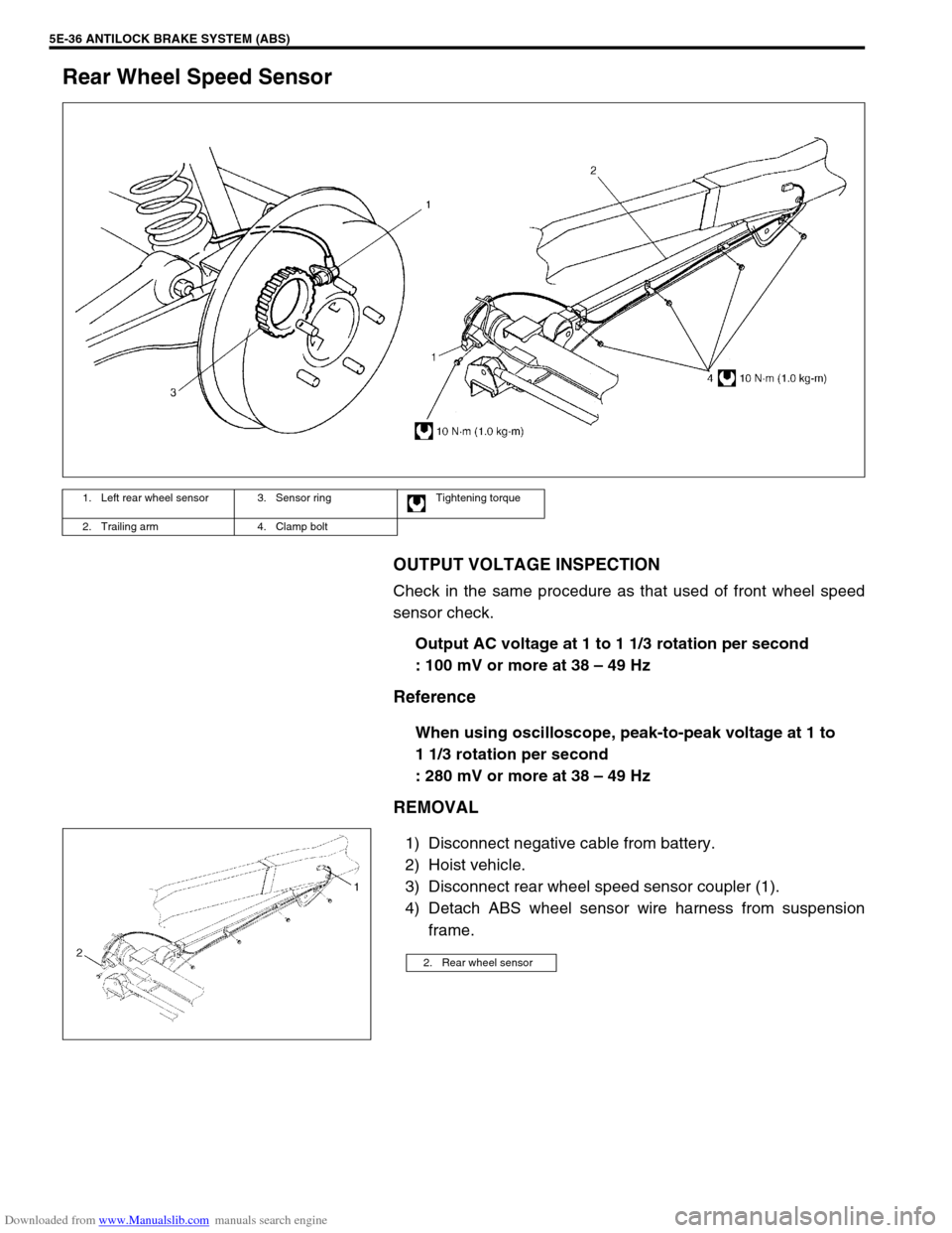
3) Disconnect rear wheel speed sensor coupler (1).
4) Detach ABS wheel sensor wire harness from suspension
frame.
1. Left rear wheel sensor 3. Sensor ring Tightening torque
2. Trailing arm 4. Clamp bolt
2. Rear wheel sensor
Page 357 of 687
Downloaded from www.Manualslib.com manuals search engine 5E-40 ANTILOCK BRAKE SYSTEM (ABS)
Tightening Torque Specification
Special Tool
Fastening partTightening torque
Nm kg-m lb-ft
Brake pipe flare nuts 16 1.6 11.6
ABS hydraulic unit / control module assembly bracket bolts 11 1.1 8.0
ABS hydraulic unit / control module assembly bolts 9 0.9 6.5
Front wheel speed sensor bolt 10 1.0 7.2
Front wheel speed sensor harness clamp bolts 10 1.0 7.2
Rear wheel speed sensor bolt 10 1.0 7.2
Rear wheel speed sensor harness clamp bolts 10 1.0 7.2
G sensor bolts 23 2.3 17.0
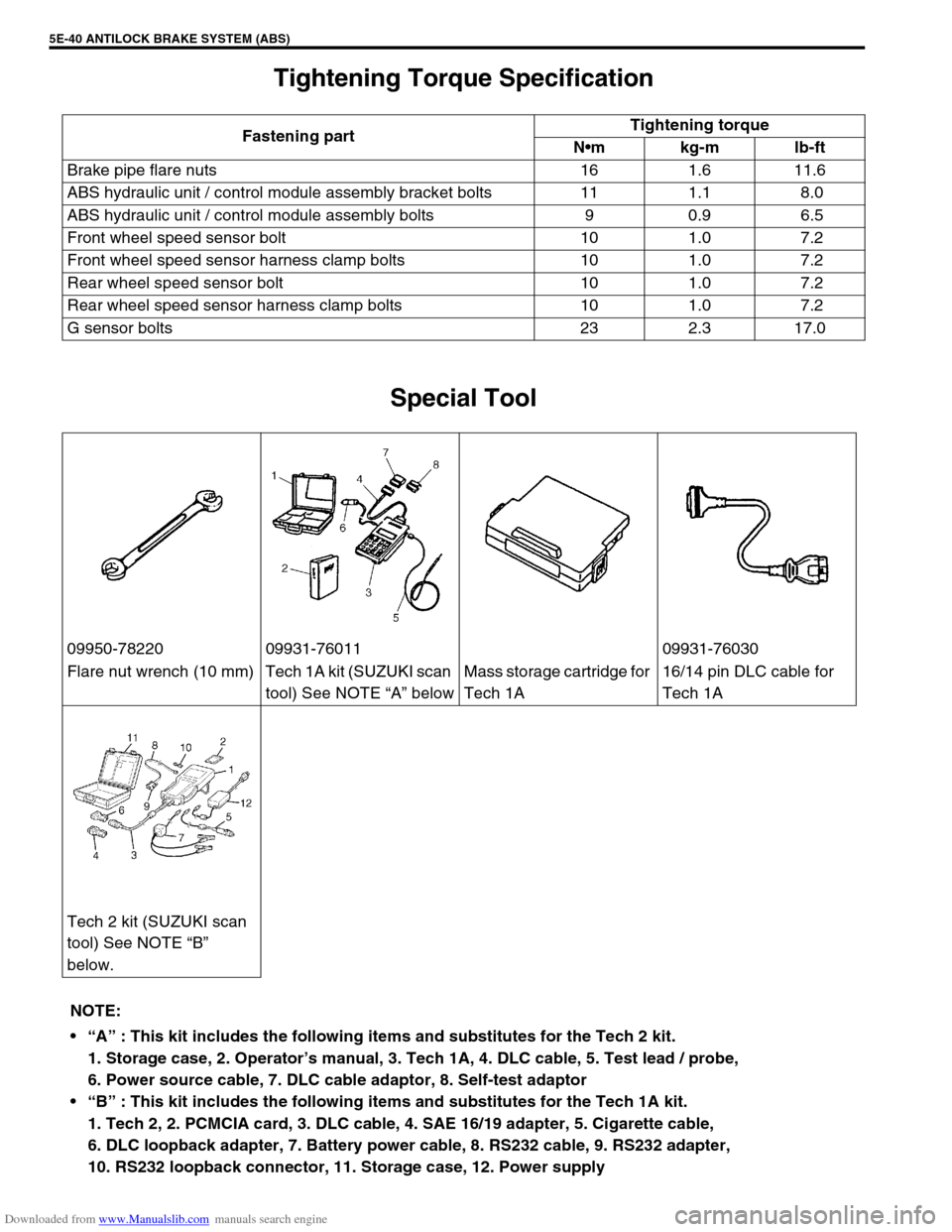
09950-78220 09931-76011 09931-76030
Flare nut wrench (10 mm) Tech 1A kit (SUZUKI scan
tool) See NOTE “A” belowMass storage cartridge for
Tech 1A16/14 pin DLC cable for
Tech 1A
Tech 2 kit (SUZUKI scan
tool) See NOTE “B”
below.
NOTE:
“A” : This kit includes the following items and substitutes for the Tech 2 kit.
1. Storage case, 2. Operator’s manual, 3. Tech 1A, 4. DLC cable, 5. Test lead / probe,
6. Power source cable, 7. DLC cable adaptor, 8. Self-test adaptor
“B” : This kit includes the following items and substitutes for the Tech 1A kit.
1. Tech 2, 2. PCMCIA card, 3. DLC cable, 4. SAE 16/19 adapter, 5. Cigarette cable,
6. DLC loopback adapter, 7. Battery power cable, 8. RS232 cable, 9. RS232 adapter,
10. RS232 loopback connector, 11. Storage case, 12. Power supply
Page 551 of 687

Downloaded from www.Manualslib.com manuals search engine 6A1-70 ENGINE MECHANICAL (M13 ENGINE)
INSTALLATION
1) Apply engine oil to pistons, rings, cylinder walls, connecting
rod bearings and crankpins.
2) Install guide hoses (1) over connecting rod bolts.
These guide hoses protect crank pin and threads of rod bolt
from damage during installation of connecting rod and piston
assembly.
3) When installing piston and connecting rod assembly into cyl-
inder bore, point front mark on piston head to crankshaft pul-
ley side.
4) Install piston and connecting rod assembly into cylinder
bore. Use special tool (Piston ring compressor) to compress
rings. Guide connecting rod into place on crankshaft.
Using a hammer handle, tap piston head to install piston into
bore. Hold ring compressor firmly against cylinder block until
all piston rings have entered cylinder bore.
Special tool
(A) : 09916-77310 NOTE:
Do not apply oil between connecting rod and bearing or
between bearing cap and bearing.
A : Crankshaft pulley side
B : Flywheel side
Page 557 of 687
Downloaded from www.Manualslib.com manuals search engine 6A1-76 ENGINE MECHANICAL (M13 ENGINE)
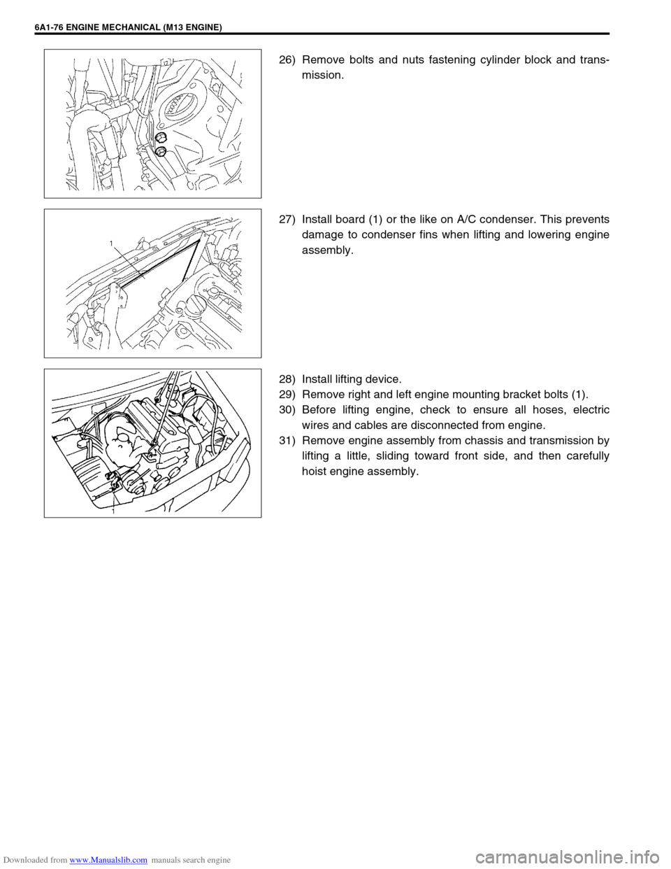
26) Remove bolts and nuts fastening cylinder block and trans-
mission.
27) Install board (1) or the like on A/C condenser. This prevents
damage to condenser fins when lifting and lowering engine
assembly.
28) Install lifting device.
29) Remove right and left engine mounting bracket bolts (1).
30) Before lifting engine, check to ensure all hoses, electric
wires and cables are disconnected from engine.
31) Remove engine assembly from chassis and transmission by
lifting a little, sliding toward front side, and then carefully
hoist engine assembly.
Page 581 of 687
Downloaded from www.Manualslib.com manuals search engine 6B-4 ENGINE COOLING
Water Pump
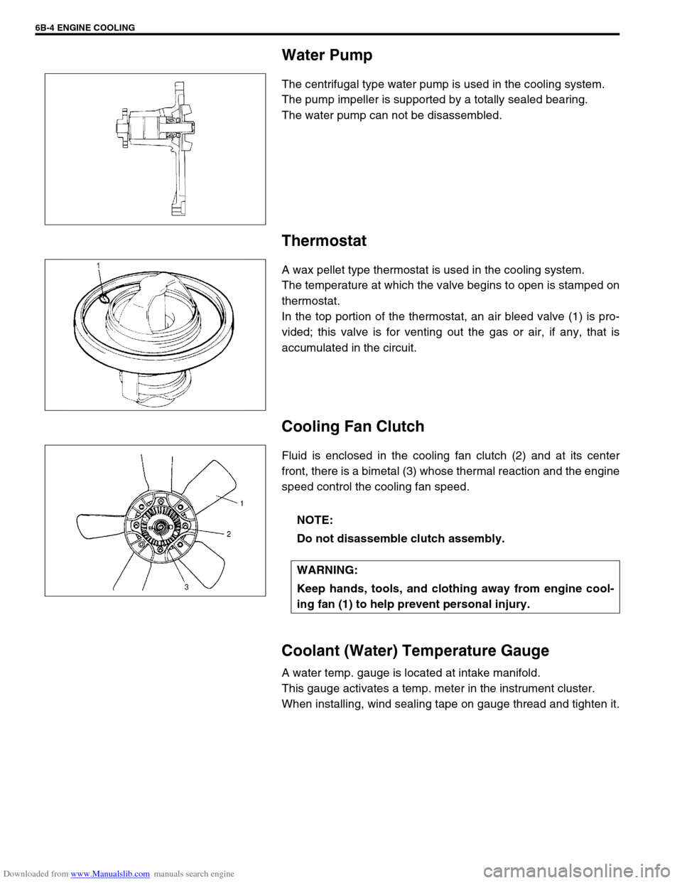
The centrifugal type water pump is used in the cooling system.
The pump impeller is supported by a totally sealed bearing.
The water pump can not be disassembled.
Thermostat
A wax pellet type thermostat is used in the cooling system.
The temperature at which the valve begins to open is stamped on
thermostat.
In the top portion of the thermostat, an air bleed valve (1) is pro-
vided; this valve is for venting out the gas or air, if any, that is
accumulated in the circuit.
Cooling Fan Clutch
Fluid is enclosed in the cooling fan clutch (2) and at its center
front, there is a bimetal (3) whose thermal reaction and the engine
speed control the cooling fan speed.
Coolant (Water) Temperature Gauge
A water temp. gauge is located at intake manifold.
This gauge activates a temp. meter in the instrument cluster.
When installing, wind sealing tape on gauge thread and tighten it.
NOTE:
Do not disassemble clutch assembly.
WARNING:
Keep hands, tools, and clothing away from engine cool-
ing fan (1) to help prevent personal injury.
Page 585 of 687
Downloaded from www.Manualslib.com manuals search engine 6B-8 ENGINE COOLING
5) Tighten hose clamps and inspect all hoses.
Replace hoses whenever cracked, swollen or otherwise
deteriorated.
6) Clean frontal area of radiator core.
Cooling System Flush and Refill
1) Remove radiator cap when engine is cool:
Turn cap slowly to the left until it reaches a “stop” (Do not
press down while turning it).
Wait until pressure is relieved (indicated by a hissing sound)
then press down on cap and continue to turn it to the left.
2) With radiator cap removed, run engine until upper radiator
hose is hot (this shows that thermostat is open and coolant is
flowing through system).
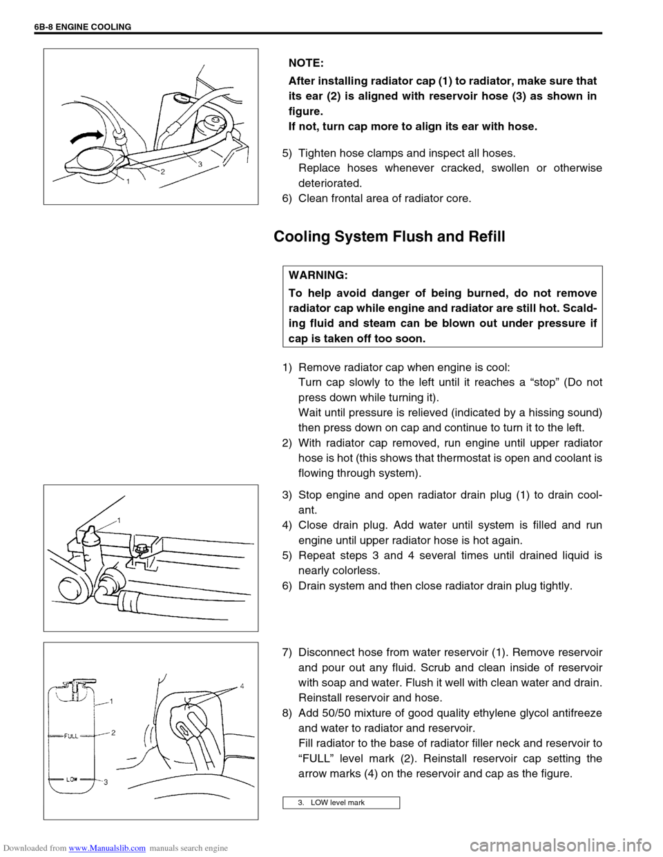
3) Stop engine and open radiator drain plug (1) to drain cool-
ant.
4) Close drain plug. Add water until system is filled and run
engine until upper radiator hose is hot again.
5) Repeat steps 3 and 4 several times until drained liquid is
nearly colorless.
6) Drain system and then close radiator drain plug tightly.
7) Disconnect hose from water reservoir (1). Remove reservoir
and pour out any fluid. Scrub and clean inside of reservoir
with soap and water. Flush it well with clean water and drain.
Reinstall reservoir and hose.
8) Add 50/50 mixture of good quality ethylene glycol antifreeze
and water to radiator and reservoir.
Fill radiator to the base of radiator filler neck and reservoir to
“FULL” level mark (2). Reinstall reservoir cap setting the
arrow marks (4) on the reservoir and cap as the figure. NOTE:
After installing radiator cap (1) to radiator, make sure that
its ear (2) is aligned with reservoir hose (3) as shown in
figure.
If not, turn cap more to align its ear with hose.
WARNING:
To help avoid danger of being burned, do not remove
radiator cap while engine and radiator are still hot. Scald-
ing fluid and steam can be blown out under pressure if
cap is taken off too soon.
3. LOW level mark
Page 665 of 687

Downloaded from www.Manualslib.com manuals search engine 6G-6 CRANKING SYSTEM
DISASSEMBLY AND REASSEMBLY
NOTE:
Make sure to apply grease before assembly, where are indicated “A” in the figure below.
Spare parts have been lubricated.
1. Front housing 6. Over-running clutch 11. Magnetic switch 16. Packing 21. Rear bracket
2. Bush 7. Lever 12. Ball 17. Yoke 22. Rear bush
3. Snap ring 8. Plunger 13. Internal gear 18. Armature 23. Brush spring
4. Pinion stop ring 9. Plate 14. Planetary carrier shaft 19. Brush Apply grease (99000-25010)
5. Pinion gear 10. Seal rubber 15. Planetary gear 20. Brush holder Do not reuse.
Page 672 of 687
Downloaded from www.Manualslib.com manuals search engine CHARGING SYSTEM 6H-5
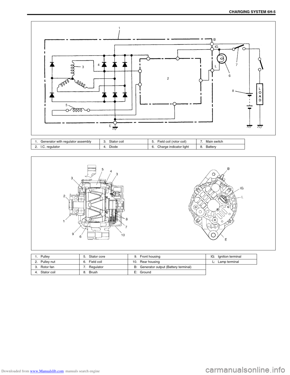
1. Generator with regulator assembly 3. Stator coil 5. Field coil (rotor coil) 7. Main switch
2. I.C. regulator 4. Diode 6. Charge indicator light 8. Battery
1. Pulley 5. Stator core 9. Front housing IG: Ignition terminal
2. Pulley nut 6. Field coil 10. Rear housing L: Lamp terminal
3. Rotor fan 7. Regulator B: Generator output (Battery terminal)
4. Stator coil 8. Brush E: Ground
Page 680 of 687
Downloaded from www.Manualslib.com manuals search engine CHARGING SYSTEM 6H-13
Remounting
1) Mount generator on the generator bracket.
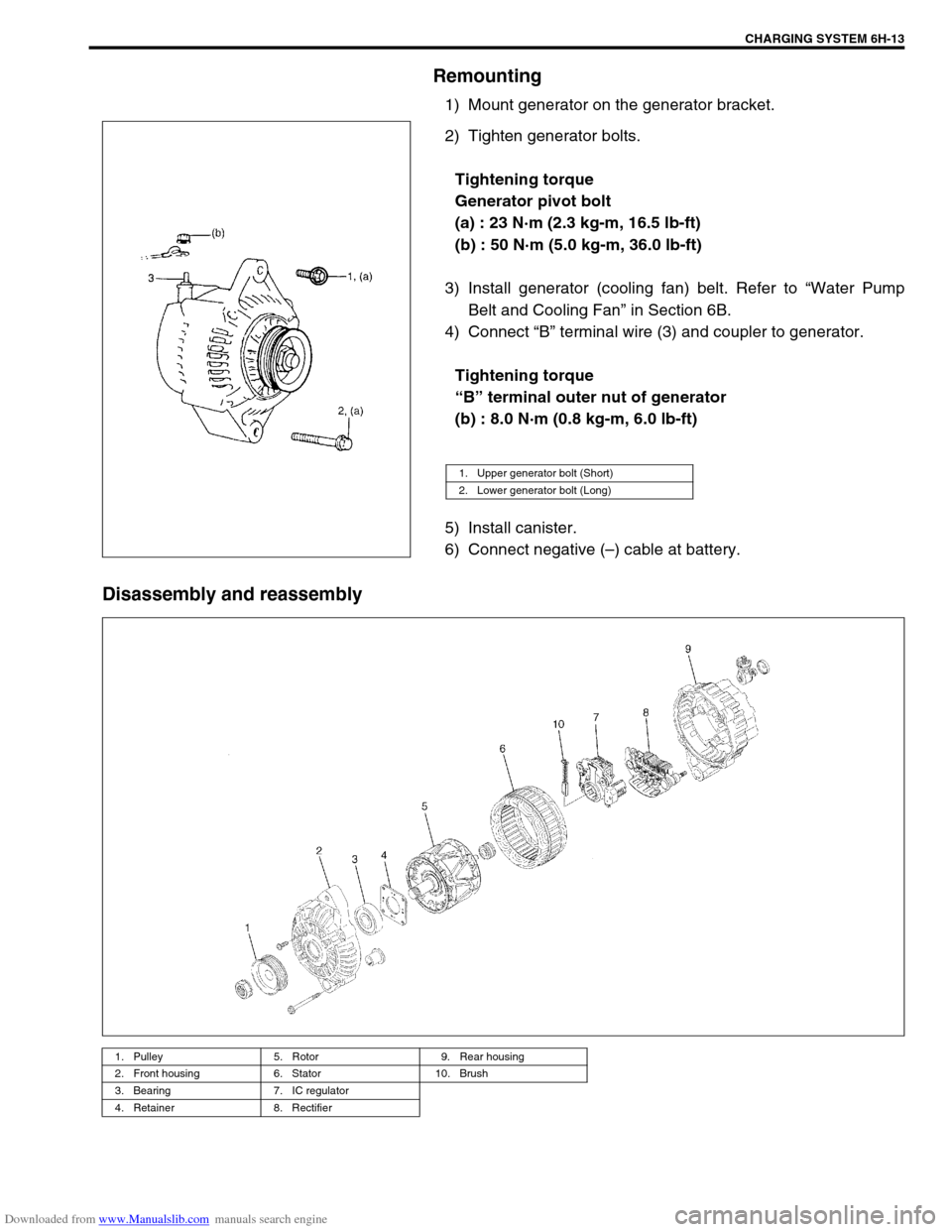
2) Tighten generator bolts.
Tightening torque
Generator pivot bolt
(a) : 23 N·m (2.3 kg-m, 16.5 lb-ft)
(b) : 50 N·m (5.0 kg-m, 36.0 lb-ft)
3) Install generator (cooling fan) belt. Refer to “Water Pump
Belt and Cooling Fan” in Section 6B.
4) Connect “B” terminal wire (3) and coupler to generator.
Tightening torque
“B” terminal outer nut of generator
(b) : 8.0 N·m (0.8 kg-m, 6.0 lb-ft)
5) Install canister.
6) Connect negative (–) cable at battery.
Disassembly and reassembly
1. Upper generator bolt (Short)
2. Lower generator bolt (Long)
1. Pulley 5. Rotor 9. Rear housing
2. Front housing 6. Stator 10. Brush
3. Bearing 7. IC regulator
4. Retainer 8. Rectifier