AIR CON SUZUKI JIMNY 2005 3.G Service Workshop Manual
[x] Cancel search | Manufacturer: SUZUKI, Model Year: 2005, Model line: JIMNY, Model: SUZUKI JIMNY 2005 3.GPages: 687, PDF Size: 13.38 MB
Page 318 of 687

Downloaded from www.Manualslib.com manuals search engine ANTILOCK BRAKE SYSTEM (ABS) 5E-1
6F1
6F2
6G
6H
6K
7A
7A1
7B1
7C1
7D
7E
7F
8E
5E
9
10
10A
10B
10
10A
10B
SECTION 5E
ANTILOCK BRAKE SYSTEM (ABS)
CONTENTS
General Description ....................................... 5E-2
System Schematic ....................................... 5E-3
ABS Component Parts Location .................. 5E-4
ABS Control Module ..................................... 5E-5
Self-diagnosis function ............................. 5E-5
Fail-safe function ...................................... 5E-5
Diagnosis ........................................................ 5E-6
Precaution in Diagnosing Troubles .............. 5E-6
ABS Diagnostic Flow Table .......................... 5E-6
“ABS” Warning Lamp Check ........................ 5E-9
Diagnostic Trouble Code (DTC) Check ........ 5E-9
DTC Check (Using SUZUKI Scan Tool) ..... 5E-10
Diagnostic Trouble Code (DTC)
Clearance ................................................... 5E-10
Diagnostic Trouble Code (DTC) Table ....... 5E-11
System Circuit ............................................ 5E-12
Table – A “ABS” Warning Lamp Circuit
Check – Lamp Does Not Come “ON”
at Ignition Switch ON .................................. 5E-14
Table – B “ABS” Warning Lamp Circuit
Check – Lamp Comes “ON” Steady ........... 5E-15
Table – C “ABS” Warning Lamp Circuit
Check – Lamp Flashes Continuously
While Ignition Switch is ON ........................ 5E-16
Table – D Code (DTC) is Not Outputted
Even With Diag. Switch Terminal
Connected to Ground. ................................ 5E-17
DTC C1015 (DTC 15) – G Sensor
Circuit ......................................................... 5E-18
DTC C1016 (DTC 16) – Stop Lamp
Circuit ......................................................... 5E-20
DTC C1021 (DTC 21), DTC C1022
(DTC 22) – Right Front Wheel Speed
Sensor Circuit ............................................. 5E-21
DTC C1025 (DTC 25), DTC C1026
(DTC 26) – Left Front Wheel Speed
Sensor Circuit ............................................. 5E-21DTC C1031 (DTC 31), DTC C1032
(DTC 32) – Right Rear Wheel Speed
Sensor Circuit ............................................ 5E-21
DTC C1035 (DTC 35), DTC C1036
(DTC 36) – Left Rear Wheel Speed
Sensor Circuit ............................................ 5E-21
DTC C1041 (DTC 41), DTC C1042
(DTC 42) – Right Front Solenoid Circuit .... 5E-24
DTC C1045 (DTC 45), DTC C1046
(DTC 46) – Left Front Solenoid Circuit....... 5E-24
DTC C1055 (DTC 55), DTC C1056
(DTC 56) – Rear Solenoid Circuit .............. 5E-24
DTC C1057 (DTC 57) – Power Source
Circuit ......................................................... 5E-25
DTC C1061 (DTC 61) – ABS Pump
Motor Circuit............................................... 5E-26
DTC C1063 (DTC 63) – ABS Fail Safe
Circuit ......................................................... 5E-27
DTC C1071 (DTC 71) – ABS Control
Module ....................................................... 5E-28
On-Vehicle Service ...................................... 5E-29
Precaution .................................................. 5E-29
ABS Hydraulic Unit Operation Check ........ 5E-29
ABS Hydraulic Unit / Control Module
Assembly ................................................... 5E-30
Front Wheel Speed Sensor........................ 5E-32
Front Wheel Sensor Ring........................... 5E-35
Rear Wheel Speed Sensor ........................ 5E-36
Rear Wheel Sensor Ring ........................... 5E-38
G Sensor .................................................... 5E-39
Tightening Torque Specification ................ 5E-40
Special Tool .................................................. 5E-40 NOTE:
All brake fasteners are important attaching parts in that they could affect the performance of vital
parts and systems, and/or could result in major repair expense. They must be replaced with one of
same part number or with an equivalent part if replacement part of lesser quality or substitute design.
Torque values must be used as specified during reassembly to assure proper retention of all parts.
There is to be no welding as it may result in extensive damage and weakening of the metal.
Page 323 of 687

Downloaded from www.Manualslib.com manuals search engine 5E-6 ANTILOCK BRAKE SYSTEM (ABS)
Diagnosis
To ensure that the trouble diagnosis is done accurately and smoothly, observe “Precautions in Diagnosing Trou-
bles” and follow “ABS Diagnostic Flow Table”.
Precaution in Diagnosing Troubles
If the vehicles was operated in any of the following ways, “ABS” warning lamp may light momentarily but this
does not indicate anything abnormal in ABS.
–The vehicle was driven with parking brake pulled.
–The vehicle was driven with brake dragging.
–The vehicle was stuck in mud, sand, etc.
–Wheel spin occurred while driving.
–Wheel(s) was rotated while the vehicle was jacked up.
Be sure to read “Precautions for Electronic Circuit Service” in Section 0A before inspection and observe
what is written there.
Be sure to use the trouble diagnosis procedure as described in the flow table. Failure to follow the flow table
may result in incorrect diagnosis. Some other diag. trouble code may be stored by mistake in the memory of
ABS control module during inspection.
ABS Diagnostic Flow Table
Refer to the following for the details of each step.
Step Action Yes No
1 Perform customer complaint analysis, problem symptom confir-
mation and diagnostic trouble code check record and clear-
ance.
Is there any trouble code?Go to Step 2. Go to Step 5.
2 Perform driving test.
Is trouble symptom identified?Go to Step 3. Go to Step 6.
3 Check diagnostic trouble code.
Is it malfunction code?Go to Step 4. Go to Step 5.
4 Inspect and repair referring to applicable diagnostic trouble
code table in this section. Then perform final confirmation test
after clearing diagnostic trouble code.
Is trouble recur?Go to Step 7. End.
5 Inspect and repair referring to “Diagnosis Table” in Section 5.
Then perform final confirmation test after clearing diagnostic
trouble code.
Is trouble recur?Go to Step 7. End.
6 Check for intermittent problems referring to “Intermittent and
Poor Connection” in Section 0A and related circuit of trouble
code recorded in Step 3. Then perform final confirmation test
after clearing diagnostic trouble code.
Is trouble recur?Go to Step 7. End.
7 Perform diagnostic trouble code check record and clearance.
Is there any trouble code?Go to Step 4. Go to Step 5.
Page 324 of 687

Downloaded from www.Manualslib.com manuals search engine ANTILOCK BRAKE SYSTEM (ABS) 5E-7
1) MALFUNCTION ANALYSIS
a) Customer Complaint Analysis
Record details of the problem (failure, complaint) and how it occurred as described by the customer.
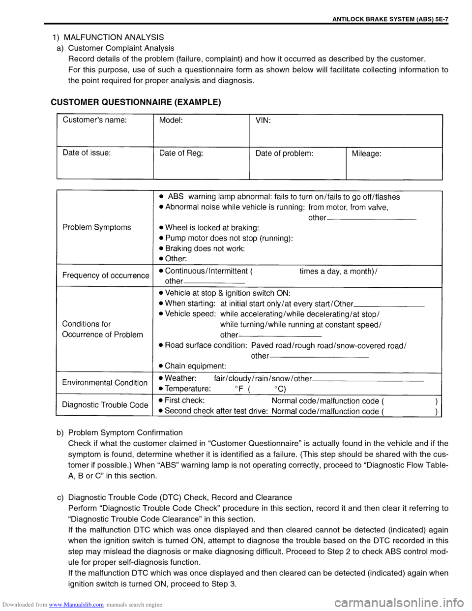
For this purpose, use of such a questionnaire form as shown below will facilitate collecting information to
the point required for proper analysis and diagnosis.
CUSTOMER QUESTIONNAIRE (EXAMPLE)
b) Problem Symptom Confirmation
Check if what the customer claimed in “Customer Questionnaire” is actually found in the vehicle and if the
symptom is found, determine whether it is identified as a failure. (This step should be shared with the cus-
tomer if possible.) When “ABS” warning lamp is not operating correctly, proceed to “Diagnostic Flow Table-
A, B or C” in this section.
c) Diagnostic Trouble Code (DTC) Check, Record and Clearance
Perform “Diagnostic Trouble Code Check” procedure in this section, record it and then clear it referring to
“Diagnostic Trouble Code Clearance” in this section.
If the malfunction DTC which was once displayed and then cleared cannot be detected (indicated) again
when the ignition switch is turned ON, attempt to diagnose the trouble based on the DTC recorded in this
step may mislead the diagnosis or make diagnosing difficult. Proceed to Step 2 to check ABS control mod-
ule for proper self-diagnosis function.
If the malfunction DTC which was once displayed and then cleared can be detected (indicated) again when
ignition switch is turned ON, proceed to Step 3.
Page 325 of 687

Downloaded from www.Manualslib.com manuals search engine 5E-8 ANTILOCK BRAKE SYSTEM (ABS)
2) DRIVING TEST
Test drive the vehicle at 40 km/h for more than a minute and check if any trouble symptom (such as abnor-
mal lighting of “ABS” warning lamp) exists.
If the malfunction DTC is confirmed again at ignition switch ON, driving test as described in above is not nec-
essary. Proceed to Step 3.
3) DIAGNOSTIC TROUBLE CODE CHECK
Recheck diagnostic trouble code referring to “DTC Check” in this section.
4) DIAGNOSTIC TROUBLE CODE FLOW TABLE
According to Diagnostic Flow Table for the diagnostic trouble code confirmed in Step 3, locate the cause of
the trouble, namely in a sensor, switch, wire harness, connector, actuator, ABS control module or other part
and repair or replace faulty parts.
5)“DIAGNOSIS TABLE” IN SECTION 5
Check the parts or system suspected as a possible cause referring to “Diagnosis Table” in Section 5 and
based on symptoms appearing on the vehicle (symptoms obtained through Step 1)-a, 1)-b and 2) and repair
or replace faulty parts, if any.
6) CHECK FOR INTERMITTENT PROBLEM
Check parts where an intermittent trouble is easy to occur (e.g., wire harness, connector, etc.), referring to
Intermittent Trouble in Section 0A and related circuit of trouble code recorded in Step 1)-c.
7) FINAL CONFIRMATION TEST
Confirm that the problem symptom has gone and the ABS is free from any abnormal conditions. If what has
been repaired is related to the malfunction DTC, clear the DTC once and perform test driving and confirm
that a normal code is indicated.
Page 327 of 687

Downloaded from www.Manualslib.com manuals search engine 5E-10 ANTILOCK BRAKE SYSTEM (ABS)
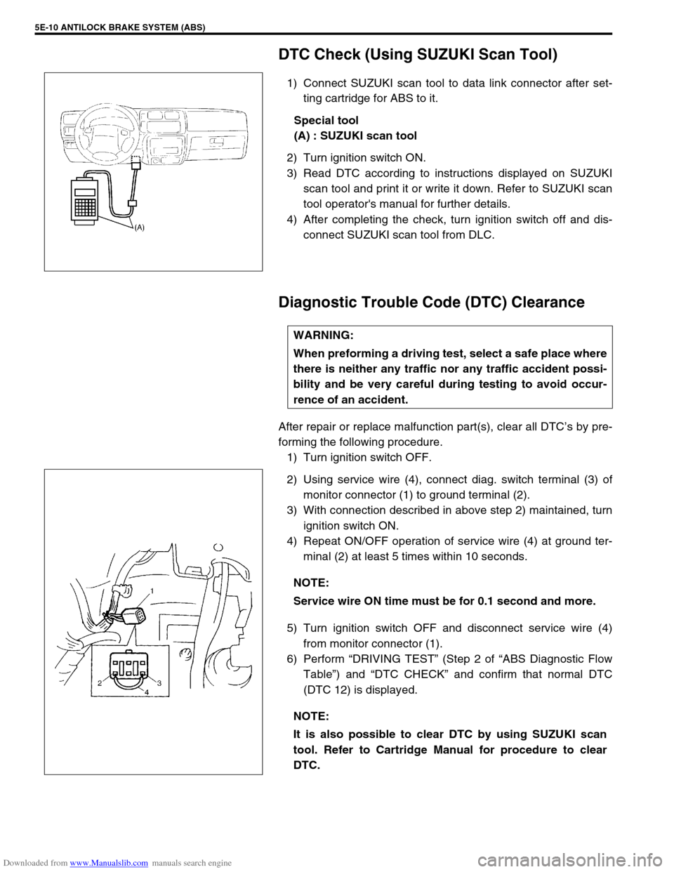
DTC Check (Using SUZUKI Scan Tool)
1) Connect SUZUKI scan tool to data link connector after set-
ting cartridge for ABS to it.
Special tool
(A) : SUZUKI scan tool
2) Turn ignition switch ON.
3) Read DTC according to instructions displayed on SUZUKI
scan tool and print it or write it down. Refer to SUZUKI scan
tool operator's manual for further details.
4) After completing the check, turn ignition switch off and dis-
connect SUZUKI scan tool from DLC.
Diagnostic Trouble Code (DTC) Clearance
After repair or replace malfunction part(s), clear all DTC’s by pre-
forming the following procedure.
1) Turn ignition switch OFF.
2) Using service wire (4), connect diag. switch terminal (3) of
monitor connector (1) to ground terminal (2).
3) With connection described in above step 2) maintained, turn
ignition switch ON.
4) Repeat ON/OFF operation of service wire (4) at ground ter-
minal (2) at least 5 times within 10 seconds.
5) Turn ignition switch OFF and disconnect service wire (4)
from monitor connector (1).
6) Perform “DRIVING TEST” (Step 2 of “ABS Diagnostic Flow
Table”) and “DTC CHECK” and confirm that normal DTC
(DTC 12) is displayed.
WARNING:
When preforming a driving test, select a safe place where
there is neither any traffic nor any traffic accident possi-
bility and be very careful during testing to avoid occur-
rence of an accident.
NOTE:
Service wire ON time must be for 0.1 second and more.
NOTE:
It is also possible to clear DTC by using SUZUKI scan
tool. Refer to Cartridge Manual for procedure to clear
DTC.
Page 332 of 687

Downloaded from www.Manualslib.com manuals search engine ANTILOCK BRAKE SYSTEM (ABS) 5E-15
Table – B “ABS” Warning Lamp Circuit Check – Lamp Comes “ON” Steady
Refer to TABLE – A for System Circuit Diagram and Circuit Description.
INSPECTION
3 1) Remove combination meter.
Is bulb of ABS warning lamp in good condition?“R/Bl” circuit shorted to ground.
If OK, replace ABS warning cir-
cuit (lamp driver module).Replace bulb.
4 Is IG fuse in good condition? Open in “B/W” wire to combina-
tion meter or poor connection.Repair and replace. Step Action Yes No
Step Action Yes No
1 Perform diagnostic trouble code check. Is there
any DTC (including code No.12, NO CODES on
SUZUKI scan tool) exists?Go to step 2. Go to step 3.
2 Is malfunction DTC (other than code No.12)
exists at step 1?Go to step 7 of ABS diag-
nostic flow table in this
section.Go to step 3.
3 1) Disconnect ABS hydraulic unit / control
module connector.
2) Check for proper connection to ABS hydrau-
lic unit / control module connector at termi-
nals “A14” and “A18”.
3) If OK, turn ignition switch “ON” and mea-
sure voltage at terminal “A18” of connector.
Is it 10 – 14 V?Go to step 4.“B/W” circuit open.
4 1) With ABS control module connector discon-
nected, turn ignition switch ON and light
ABS warning lamp.
2) Connect terminal “A14” of disconnected
connector to ground using service wire.
Does “ABS warning lamp” turn off?Go to step 5.“R/Bl” circuit open.
If wire and connection are
OK, replace ABS lamp
driver module.
5 1) Measure resistance from connector termi-
nal “A24” to body ground.
Is continuity indicated?Substitute a known-good
ABS hydraulic unit / con-
trol module assembly and
recheck.“B” circuit open.
Page 334 of 687

Downloaded from www.Manualslib.com manuals search engine ANTILOCK BRAKE SYSTEM (ABS) 5E-17
Table – D Code (DTC) is Not Outputted Even With Diag. Switch Terminal Con-
nected to Ground.
CIRCUIT DESCRIPTION
When the diag. switch terminal is connected to the ground with the ignition switch turned ON, the ABS control
module outputs a diagnostic trouble code by flashing “ABS” warning lamp.
INSPECTION
1.“ABS” warning lamp in combination meter 3-1. Diag. switch terminal 4-1. Lock position
2. ABS hydraulic unit / control module assembly 3-2. Diag. ground terminal 4-2. Unlock position
3. Monitor connector 4. ABS hydraulic unit / control module connector of harness
Step Action Yes No
1 Is it shorted diag. switch terminal and ground
terminal by service wire properly?Go to step 2. Connect service wire
securely.
2 1) Disconnect service wire.
2) Disconnect ABS hydraulic unit / control
module connector.
3) Measure resistance between diag. switch
terminal and connector terminal “A12”.
Is it infinite (∞)?“P/B” circuit open. Go to step 3.
3 1) Measure resistance between ground termi-
nal of monitor connector and body ground.
Is continuity indicated?Go to step 4.“B” circuit open or poor
connection.
4 1) Check for proper connection to ABS hydrau-
lic unit / control module at terminal “A12”
and “A24”.
2) If OK, then check “ABS” warning lamp cir-
cuit referring to TABLE A, B and C.
Is it in good condition?Substitute a known-good
ABS hydraulic unit / con-
trol module assembly and
recheck.Repair “ABS” warning
lamp circuit.
Page 338 of 687

Downloaded from www.Manualslib.com manuals search engine ANTILOCK BRAKE SYSTEM (ABS) 5E-21
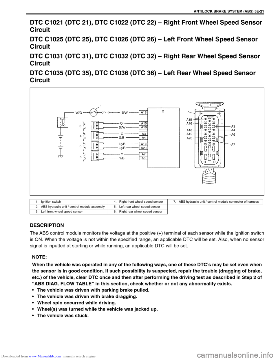
DTC C1021 (DTC 21), DTC C1022 (DTC 22) – Right Front Wheel Speed Sensor
Circuit
DTC C1025 (DTC 25), DTC C1026 (DTC 26) – Left Front Wheel Speed Sensor
Circuit
DTC C1031 (DTC 31), DTC C1032 (DTC 32) – Right Rear Wheel Speed Sensor
Circuit
DTC C1035 (DTC 35), DTC C1036 (DTC 36) – Left Rear Wheel Speed Sensor
Circuit
DESCRIPTION
The ABS control module monitors the voltage at the positive (+) terminal of each sensor while the ignition switch
is ON. When the voltage is not within the specified range, an applicable DTC will be set. Also, when no sensor
signal is inputted at starting or while running, an applicable DTC will be set.
1. Ignition switch 4. Right front wheel speed sensor 7. ABS hydraulic unit / control module connector of harness
2. ABS hydraulic unit / control module assembly 5. Left rear wheel speed sensor
3. Left front wheel speed sensor 6. Right rear wheel speed sensor
NOTE:
When the vehicle was operated in any of the following ways, one of these DTC’s may be set even when
the sensor is in good condition. If such possibility is suspected, repair the trouble (dragging of brake,
etc.) of the vehicle, clear DTC once and then after performing the driving test as described in Step 2 of
“ABS DIAG. FLOW TABLE” in this section, check whether or not any abnormality exists.
The vehicle was driven with parking brake pulled.
The vehicle was driven with brake dragging.
Wheel spin occurred while driving.
Wheel(s) was turned while the vehicle was jacked up.
The vehicle was stuck.
Page 339 of 687

Downloaded from www.Manualslib.com manuals search engine 5E-22 ANTILOCK BRAKE SYSTEM (ABS)
INSPECTION
Step Action Yes No
1 1) Disconnect the applicable sensor connector with ignition
switch OFF.
2) Measure resistance between sensor terminals.
Resistance of wheel speed sensor: 1.4 – 1.8 kΩ (at
20°C, 68°F)
3) Measure resistance between each terminal and body
ground.
Insulation resistance: 1MΩ or higher
Were measured resistance values in step 2) and 3) as spec-
ified? (See [A])Go to step 2. Replace sensor.
2 1) Ignition switch OFF.
2) Disconnect connector from ABS hydraulic unit / control
module assembly. (See [B])
3) Check for proper connection to ABS hydraulic unit / con-
trol module assembly at each sensor terminal.
4) If OK, then turn ignition switch ON and measure voltage
between sensor positive terminal of module connector
and body ground.
Is it 0V?Go to step 3. Sensor positive cir-
cuit shorted to
power.
3 1) Ignition switch OFF.
2) Connect connector to sensor.
3) Measure resistance between sensor terminals at mod-
ule connector.
4) Measure resistance between sensor positive terminal
and negative terminal of module connector, between
positive terminal and body ground.
Are measured resistance values within each specified range
described in above step 1?Go to step 4. Circuit open or
shorted to ground.
4 1) Remove wheel speed sensor.
2) Check sensor for damage or foreign material being
attached.
Is it in good condition? (See [C])Go to step 5. Clean or replace
sensor.
5 Check visually through wheel speed sensor installation hole
for following.
Ring serration (teeth) neither missing or damaged.
No foreign material being attached.
Ring not being eccentric.
Wheel bearing free from excessive play.
Are they in good condition? (See [D])Go to step 6. Clean, repair or
replace.
6 1) Install sensor to knuckle or axle housing.
2) Tighten sensor bolt to specified torque and check that
there is not any clearance between sensor and knuckle
or axle housing. (See [E])
Replace sensor if any.
Referring to “Front Wheel Speed Sensor” in this section,
check output voltage or waveform of sensor. Is proper out-
put voltage or waveform obtained?Substitute a known-
good ABS hydraulic
unit / control module
assembly and
recheck.Replace sensor and
recheck.
Page 342 of 687

Downloaded from www.Manualslib.com manuals search engine ANTILOCK BRAKE SYSTEM (ABS) 5E-25
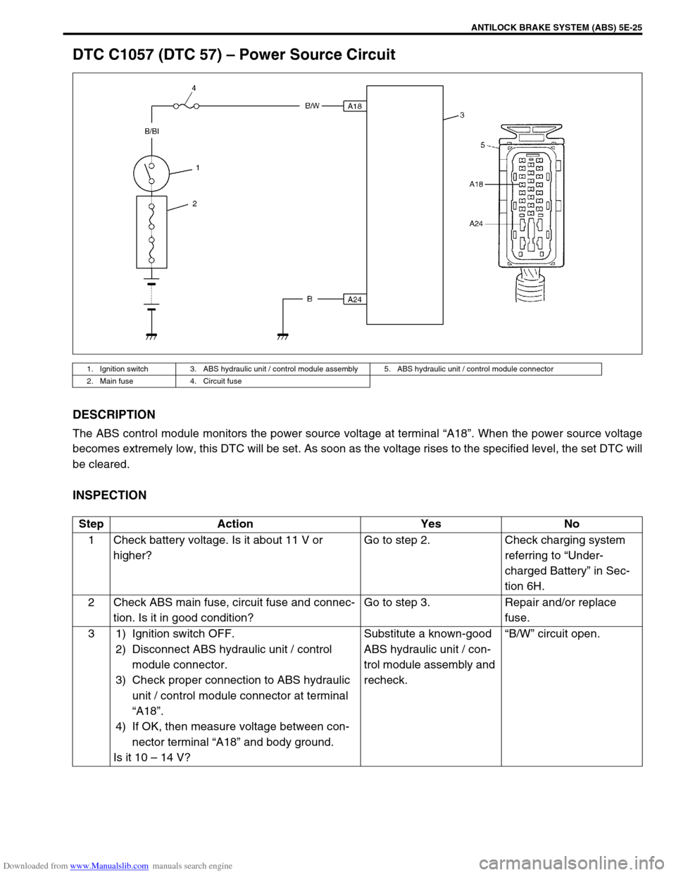
DTC C1057 (DTC 57) – Power Source Circuit
DESCRIPTION
The ABS control module monitors the power source voltage at terminal “A18”. When the power source voltage
becomes extremely low, this DTC will be set. As soon as the voltage rises to the specified level, the set DTC will
be cleared.
INSPECTION
1. Ignition switch 3. ABS hydraulic unit / control module assembly 5. ABS hydraulic unit / control module connector
2. Main fuse 4. Circuit fuse
Step Action Yes No
1 Check battery voltage. Is it about 11 V or
higher?Go to step 2. Check charging system
referring to “Under-
charged Battery” in Sec-
tion 6H.
2 Check ABS main fuse, circuit fuse and connec-
tion. Is it in good condition?Go to step 3. Repair and/or replace
fuse.
3 1) Ignition switch OFF.
2) Disconnect ABS hydraulic unit / control
module connector.
3) Check proper connection to ABS hydraulic
unit / control module connector at terminal
“A18”.
4) If OK, then measure voltage between con-
nector terminal “A18” and body ground.
Is it 10 – 14 V?Substitute a known-good
ABS hydraulic unit / con-
trol module assembly and
recheck.“B/W” circuit open.