Front axle SUZUKI JIMNY 2005 3.G Service User Guide
[x] Cancel search | Manufacturer: SUZUKI, Model Year: 2005, Model line: JIMNY, Model: SUZUKI JIMNY 2005 3.GPages: 687, PDF Size: 13.38 MB
Page 191 of 687

Downloaded from www.Manualslib.com manuals search engine 3D-18 FRONT SUSPENSION
2) When installing stabilizer, loosely assemble all components
while insuring that stabilizer is centered, side-to-side.
3) Tighten stabilizer bracket bolts (2) and stabilizer ball joint
nuts to specified torque.
Tightening torque
Stabilizer mount bracket bolts
(a) : 20 N·m (2.0 kg-m, 14.5 lb-ft)
Stabilizer ball joint nuts
(b) : 50 N·m (5.0 kg-m, 36.5 lb-ft)
4) Install front bumper.
5) Lower hoist.NOTE:
For correct installation of stabilizer bar, side-to-side, be
sure that color paint (1) on stabilizer bar aligns with
mount bush, both right and left, as shown.
NOTE:
Tighten stabilizer mount bracket bolts (2) with vehicle
hoisted a little in non-load condition.
3. Stabilizer ball joint
4. Front axle housing
Page 192 of 687
Downloaded from www.Manualslib.com manuals search engine FRONT SUSPENSION 3D-19
Front Shock Absorber
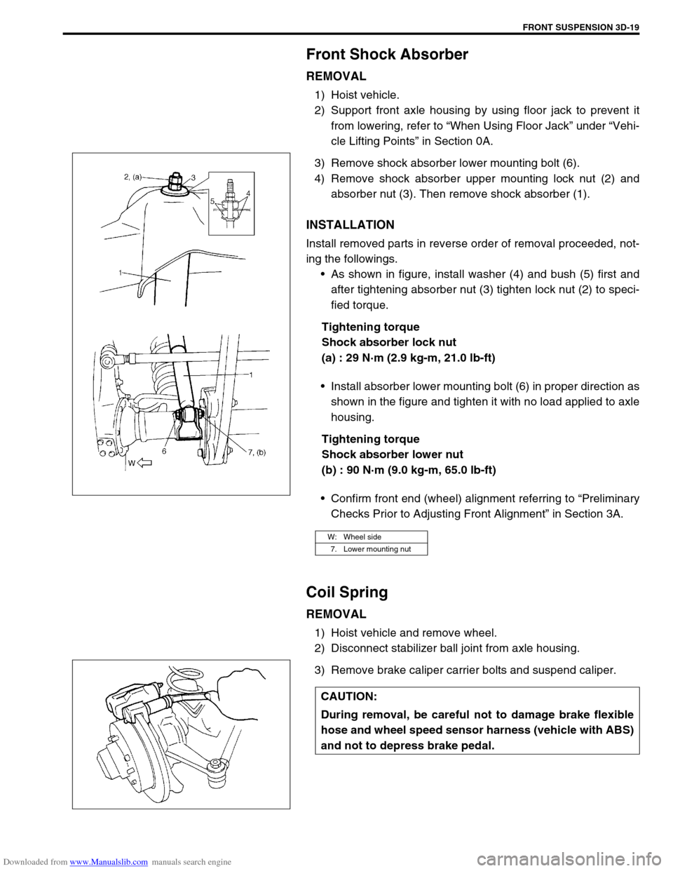
REMOVAL
1) Hoist vehicle.
2) Support front axle housing by using floor jack to prevent it
from lowering, refer to “When Using Floor Jack” under “Vehi-
cle Lifting Points” in Section 0A.
3) Remove shock absorber lower mounting bolt (6).
4) Remove shock absorber upper mounting lock nut (2) and
absorber nut (3). Then remove shock absorber (1).
INSTALLATION
Install removed parts in reverse order of removal proceeded, not-
ing the followings.
As shown in figure, install washer (4) and bush (5) first and
after tightening absorber nut (3) tighten lock nut (2) to speci-
fied torque.
Tightening torque
Shock absorber lock nut
(a) : 29 N·m (2.9 kg-m, 21.0 lb-ft)
Install absorber lower mounting bolt (6) in proper direction as
shown in the figure and tighten it with no load applied to axle
housing.
Tightening torque
Shock absorber lower nut
(b) : 90 N·m (9.0 kg-m, 65.0 lb-ft)
Confirm front end (wheel) alignment referring to “Preliminary
Checks Prior to Adjusting Front Alignment” in Section 3A.
Coil Spring
REMOVAL
1) Hoist vehicle and remove wheel.
2) Disconnect stabilizer ball joint from axle housing.
3) Remove brake caliper carrier bolts and suspend caliper.
W: Wheel side
7. Lower mounting nut
CAUTION:
During removal, be careful not to damage brake flexible
hose and wheel speed sensor harness (vehicle with ABS)
and not to depress brake pedal.
Page 193 of 687

Downloaded from www.Manualslib.com manuals search engine 3D-20 FRONT SUSPENSION
4) Support front axle housing by using floor jack.
5) Remove shock absorber lower mounting bolt (1).
6) Lower front axle housing (2) gradually as far down as where
coil spring (1) can be removed.
7) Remove coil spring (1).
INSTALLATION
Install removed parts in reverse order of removal procedures, not-
ing the followings.
1) Install coil spring (3).
2) Install absorber lower mounting bolt, refer to “Front Shock
Absorber” in this section.
3) Install caliper assembly and tighten caliper bolts to specified
torque.
Tightening torque
Brake caliper carrier bolts
(a) : 85 N·m (8.5 kg-m, 61.5 lb-ft)
4) Connect stabilizer ball joint to axle housing and tighten nut
referring to “Stabilizer Bar” in this section for tightening
torque specification. NOTE:
When supporting axle housing, it should be in non-load
condition.
NOTE:
Make sure that coil spring direction as shown.
When seating coil spring, mate spring end with
stepped part (4) of lower spring seat (2).
1. Front axle housing
U : Upper side
A : Small
B : Large
Page 195 of 687

Downloaded from www.Manualslib.com manuals search engine 3D-22 FRONT SUSPENSION
4) Remove brake disc.
5) Remove front wheel bearing lock nut as follows.
For 2WD model :
a) Remove hub cap.
b) Remove front wheel bearing lock plate (1) by loosening 4
screws (2).
For 4WD model :
a) Remove air locking hub assembly (1).
b) Remove front axle shaft circlip and wheel spindle thrust
washer.
c) Uncaulk front wheel bearing lock nut. NOTE:
If brake disc can not be removed by hand, using 8 mm
bolts.
1. Wheel hub
Page 200 of 687
Downloaded from www.Manualslib.com manuals search engine FRONT SUSPENSION 3D-27
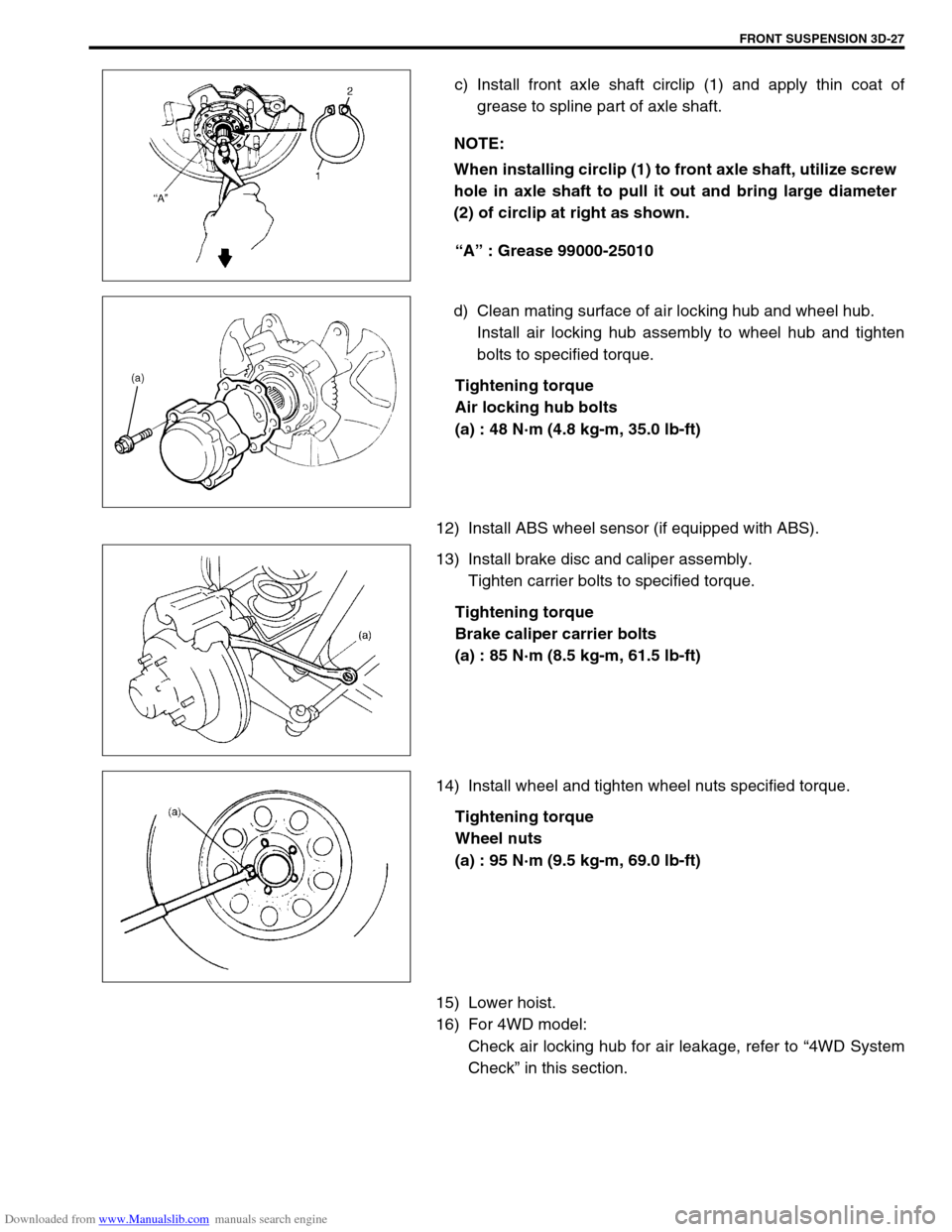
c) Install front axle shaft circlip (1) and apply thin coat of
grease to spline part of axle shaft.
“A” : Grease 99000-25010
d) Clean mating surface of air locking hub and wheel hub.
Install air locking hub assembly to wheel hub and tighten
bolts to specified torque.
Tightening torque
Air locking hub bolts
(a) : 48 N·m (4.8 kg-m, 35.0 lb-ft)
12) Install ABS wheel sensor (if equipped with ABS).
13) Install brake disc and caliper assembly.
Tighten carrier bolts to specified torque.
Tightening torque
Brake caliper carrier bolts
(a) : 85 N·m (8.5 kg-m, 61.5 lb-ft)
14) Install wheel and tighten wheel nuts specified torque.
Tightening torque
Wheel nuts
(a) : 95 N·m (9.5 kg-m, 69.0 lb-ft)
15) Lower hoist.
16) For 4WD model:
Check air locking hub for air leakage, refer to “4WD System
Check” in this section. NOTE:
When installing circlip (1) to front axle shaft, utilize screw
hole in axle shaft to pull it out and bring large diameter
(2) of circlip at right as shown.
Page 202 of 687
Downloaded from www.Manualslib.com manuals search engine FRONT SUSPENSION 3D-29
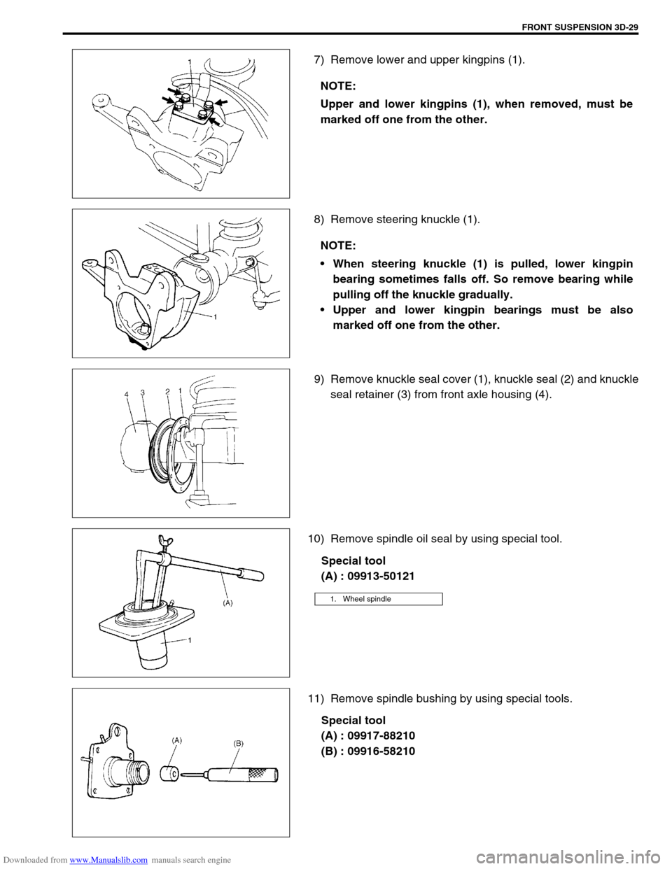
7) Remove lower and upper kingpins (1).
8) Remove steering knuckle (1).
9) Remove knuckle seal cover (1), knuckle seal (2) and knuckle
seal retainer (3) from front axle housing (4).
10) Remove spindle oil seal by using special tool.
Special tool
(A) : 09913-50121
11) Remove spindle bushing by using special tools.
Special tool
(A) : 09917-88210
(B) : 09916-58210 NOTE:
Upper and lower kingpins (1), when removed, must be
marked off one from the other.
NOTE:
When steering knuckle (1) is pulled, lower kingpin
bearing sometimes falls off. So remove bearing while
pulling off the knuckle gradually.
Upper and lower kingpin bearings must be also
marked off one from the other.
1. Wheel spindle
Page 203 of 687
Downloaded from www.Manualslib.com manuals search engine 3D-30 FRONT SUSPENSION
INSTALLATION
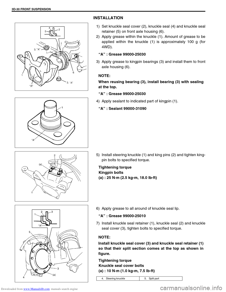
1) Set knuckle seal cover (2), knuckle seal (4) and knuckle seal
retainer (5) on front axle housing (6).
2) Apply grease within the knuckle (1). Amount of grease to be
applied within the knuckle (1) is approximately 100 g (for
4WD).
“A” : Grease 99000-25030
3) Apply grease to kingpin bearings (3) and install them to front
axle housing (6).
“A” : Grease 99000-25030
4) Apply sealant to indicated part of kingpin (1).
“A” : Sealant 99000-31090
5) Install steering knuckle (1) and king pins (2) and tighten king-
pin bolts to specified torque.
Tightening torque
Kingpin bolts
(a) : 25 N·m (2.5 kg-m, 18.0 lb-ft)
6) Apply grease to all around of knuckle seal lip.
“A” : Grease 99000-25010
7) Install knuckle seal retainer (1), knuckle seal (2) and knuckle
seal cover (3), tighten bolts to specified torque.
Tightening torque
Knuckle seal cover bolts
(a) : 10 N·m (1.0 kg-m, 7.5 lb-ft) NOTE:
When reusing bearing (3), install bearing (3) with sealing
at the top.
NOTE:
Install knuckle seal cover (3) and knuckle seal retainer (1)
so that their split section comes at the top as shown in
figure.
4. Steering knuckle 5. Split part
Page 205 of 687
Downloaded from www.Manualslib.com manuals search engine 3D-32 FRONT SUSPENSION
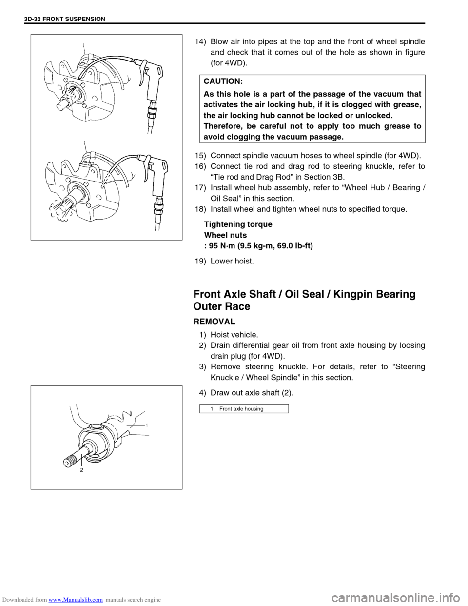
14) Blow air into pipes at the top and the front of wheel spindle
and check that it comes out of the hole as shown in figure
(for 4WD).
15) Connect spindle vacuum hoses to wheel spindle (for 4WD).
16) Connect tie rod and drag rod to steering knuckle, refer to
“Tie rod and Drag Rod” in Section 3B.
17) Install wheel hub assembly, refer to “Wheel Hub / Bearing /
Oil Seal” in this section.
18) Install wheel and tighten wheel nuts to specified torque.
Tightening torque
Wheel nuts
: 95 N·m (9.5 kg-m, 69.0 lb-ft)
19) Lower hoist.
Front Axle Shaft / Oil Seal / Kingpin Bearing
Outer Race
REMOVAL
1) Hoist vehicle.
2) Drain differential gear oil from front axle housing by loosing
drain plug (for 4WD).
3) Remove steering knuckle. For details, refer to “Steering
Knuckle / Wheel Spindle” in this section.
4) Draw out axle shaft (2).CAUTION:
As this hole is a part of the passage of the vacuum that
activates the air locking hub, if it is clogged with grease,
the air locking hub cannot be locked or unlocked.
Therefore, be careful not to apply too much grease to
avoid clogging the vacuum passage.
1. Front axle housing
Page 206 of 687
Downloaded from www.Manualslib.com manuals search engine FRONT SUSPENSION 3D-33
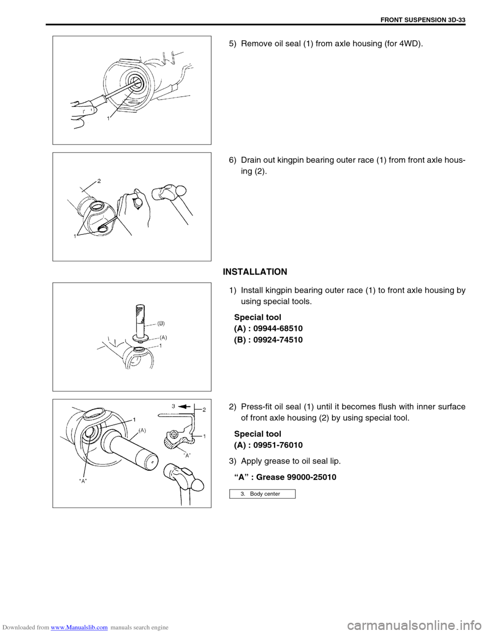
5) Remove oil seal (1) from axle housing (for 4WD).
6) Drain out kingpin bearing outer race (1) from front axle hous-
ing (2).
INSTALLATION
1) Install kingpin bearing outer race (1) to front axle housing by
using special tools.
Special tool
(A) : 09944-68510
(B) : 09924-74510
2) Press-fit oil seal (1) until it becomes flush with inner surface
of front axle housing (2) by using special tool.
Special tool
(A) : 09951-76010
3) Apply grease to oil seal lip.
“A” : Grease 99000-25010
3. Body center
Page 207 of 687

Downloaded from www.Manualslib.com manuals search engine 3D-34 FRONT SUSPENSION
4) Install axle shaft (2) to front axle housing (1) (for 4WD).
5) Install knuckle to front axle housing. For details, refer to
“Steering Knuckle / Wheel Spindle” in this section.
6) Refill front axle (differential) housing with new specified gear
oil (for 4WD). Refer to “Maintenance Service” in Section 7E
for refill.
7) After servicing, check that no oil leakage exists.
Steering Knuckle Seal
REMOVAL
1) Hoist vehicle.
2) Remove knuckle seal cover bolts and seal cover (1).
3) Cut oil seal in place with scissors or knife, and take it off.
INSTALLATION
1) Cut replacement oil seal at one place with scissors or a
knife.