Oil and filter SUZUKI JIMNY 2005 3.G Service User Guide
[x] Cancel search | Manufacturer: SUZUKI, Model Year: 2005, Model line: JIMNY, Model: SUZUKI JIMNY 2005 3.GPages: 687, PDF Size: 13.38 MB
Page 484 of 687
Downloaded from www.Manualslib.com manuals search engine ENGINE MECHANICAL (M13 ENGINE) 6A1-3
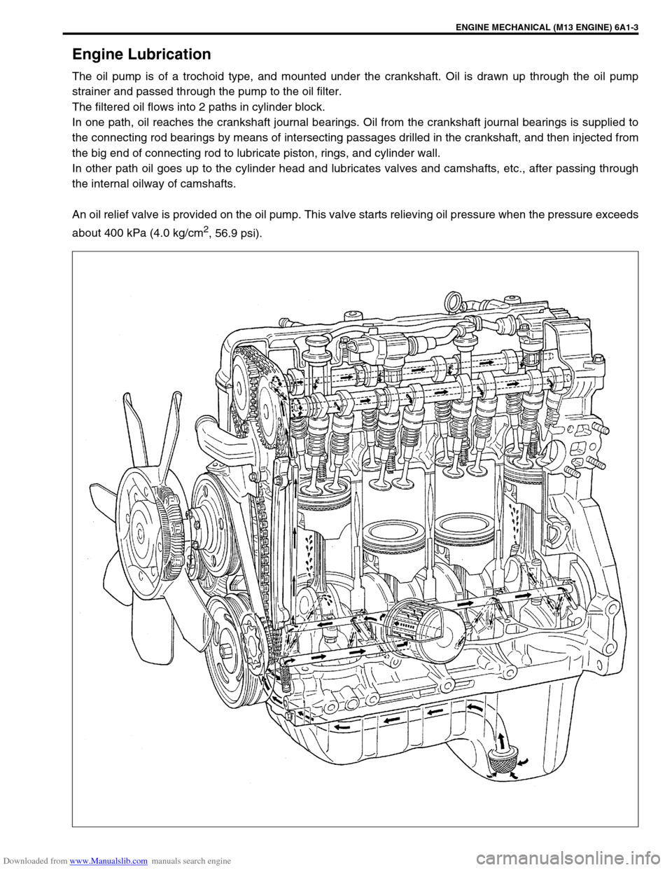
Engine Lubrication
The oil pump is of a trochoid type, and mounted under the crankshaft. Oil is drawn up through the oil pump
strainer and passed through the pump to the oil filter.
The filtered oil flows into 2 paths in cylinder block.
In one path, oil reaches the crankshaft journal bearings. Oil from the crankshaft journal bearings is supplied to
the connecting rod bearings by means of intersecting passages drilled in the crankshaft, and then injected from
the big end of connecting rod to lubricate piston, rings, and cylinder wall.
In other path oil goes up to the cylinder head and lubricates valves and camshafts, etc., after passing through
the internal oilway of camshafts.
An oil relief valve is provided on the oil pump. This valve starts relieving oil pressure when the pressure exceeds
about 400 kPa (4.0 kg/cm
2, 56.9 psi).
Page 508 of 687
Downloaded from www.Manualslib.com manuals search engine ENGINE MECHANICAL (M13 ENGINE) 6A1-27
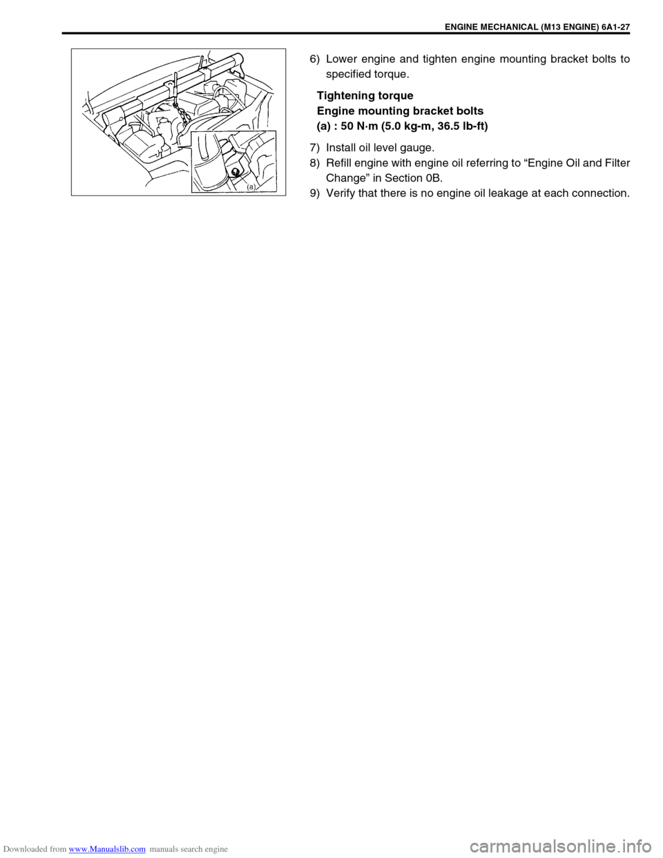
6) Lower engine and tighten engine mounting bracket bolts to
specified torque.
Tightening torque
Engine mounting bracket bolts
(a) : 50 N·m (5.0 kg-m, 36.5 lb-ft)
7) Install oil level gauge.
8) Refill engine with engine oil referring to “Engine Oil and Filter
Change” in Section 0B.
9) Verify that there is no engine oil leakage at each connection.
Page 575 of 687
Downloaded from www.Manualslib.com manuals search engine 6A1-94 ENGINE MECHANICAL (M13 ENGINE)
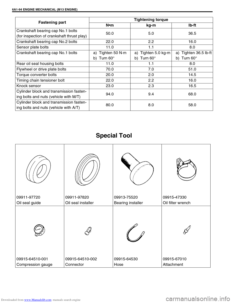
Special Tool
Crankshaft bearing cap No.1 bolts
(for inspection of crankshaft thrust play)50.0 5.0 36.5
Crankshaft bearing cap No.2 bolts 22.0 2.2 16.0
Sensor plate bolts 11.0 1.1 8.0
Crankshaft bearing cap No.1 bolts a) Tighten 50 N·m
b) Turn 60°a) Tighten 5.0 kg-m
b) Turn 60°a) Tighten 36.5 lb-ft
b) Turn 60°
Rear oil seal housing bolts 11.0 1.1 8.0
Flywheel or drive plate bolts 70.0 7.0 51.0
Torque converter bolts 20.0 2.0 14.5
Timing chain tensioner bolt 22.0 2.2 16.0
Knock sensor 23.0 2.3 16.5
Cylinder block and transmission fasten-
ing bolts and nuts (vehicle with M/T)94.0 9.4 68.0
Cylinder block and transmission fasten-
ing bolts and nuts (vehicle with A/T)80.0 8.0 58.0 Fastening partTightening torque
Nm kg-m lb-ft
09911-97720 09911-97820 09913-75520 09915-47330
Oil seal guide Oil seal installer Bearing installer Oil filter wrench
09915-64510-001 09915-64510-002 09915-64530 09915-67010
Compression gauge Connector Hose Attachment
Page 603 of 687
Downloaded from www.Manualslib.com manuals search engine 6C-8 ENGINE FUEL
INSPECTION
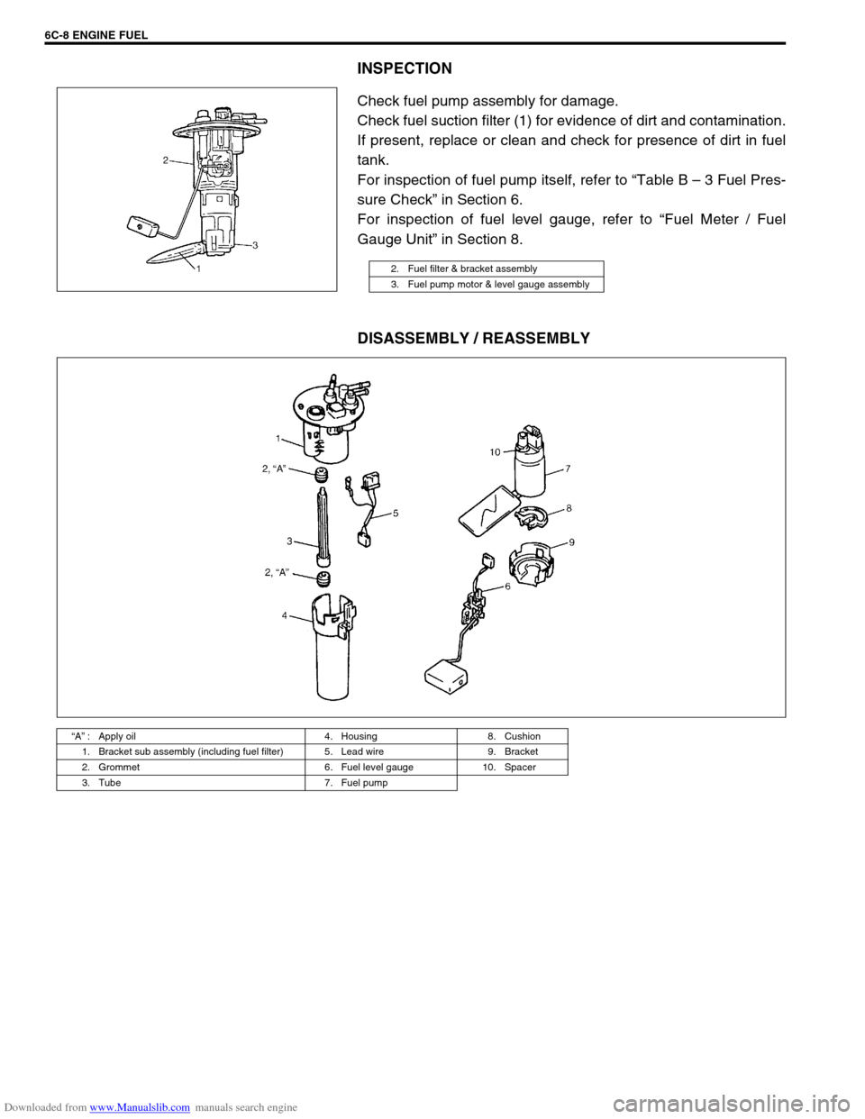
Check fuel pump assembly for damage.
Check fuel suction filter (1) for evidence of dirt and contamination.
If present, replace or clean and check for presence of dirt in fuel
tank.
For inspection of fuel pump itself, refer to “Table B – 3 Fuel Pres-
sure Check” in Section 6.
For inspection of fuel level gauge, refer to “Fuel Meter / Fuel
Gauge Unit” in Section 8.
DISASSEMBLY / REASSEMBLY
2. Fuel filter & bracket assembly
3. Fuel pump motor & level gauge assembly
“A” : Apply oil 4. Housing 8. Cushion
1. Bracket sub assembly (including fuel filter) 5. Lead wire 9. Bracket
2. Grommet 6. Fuel level gauge 10. Spacer
3. Tube 7. Fuel pump
Page 610 of 687
Downloaded from www.Manualslib.com manuals search engine ENGINE AND EMISSION CONTROL SYSTEM 6E-5
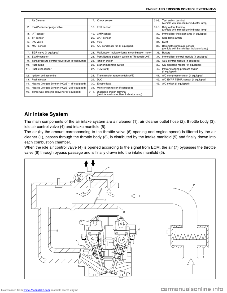
Air Intake System
The main components of the air intake system are air cleaner (1), air cleaner outlet hose (2), throttle body (3),
idle air control valve (4) and intake manifold (5).
The air (by the amount corresponding to the throttle valve (6) opening and engine speed) is filtered by the air
cleaner (1), passes through the throttle body (3), is distributed by the intake manifold (5) and finally drawn into
each combustion chamber.
When the idle air control valve (4) is opened according to the signal from ECM, the air (7) bypasses the throttle
valve (6) through bypass passage and is finally drawn into the intake manifold (5).
1. Air Cleaner 17. Knock sensor 31-2. Test switch terminal
(vehicle w/o immobilizer indicator lamp)
2. EVAP canister purge valve 18. ECT sensor 31-3. Duty output terminal
(vehicle w/o immobilizer indicator lamp)
3. IAT sensor 19. CMP sensor 32. Immobilizer indicator lamp (if equipped)
4. TP sensor 20. CKP sensor 33. Stop lamp switch
5. IAC valve 21. VSS 34. ECM
6. MAP sensor 22. A/C condenser fan (if equipped) 35. Barometric pressure sensor
(vehicle with immobilizer indicator lamp)
7. EGR valve (if equipped) 23. Malfunction indicator lamp in combination meter 36. Battery
8. EVAP canister 24. Park/Neutral position switch in TR switch (A/T) 37. Immobilizer control module (if equipped)
9. Tank pressure control valve (built-in fuel pump) 25. Ignition switch 38. ABS control module (if equipped)
10. Fuel pump 26. Starter magnetic switch 39. CO adjusting resistor (if equipped)
11. Fuel level sensor 27. TCM (A/T) 40. Power steering pressure switch
(if equipped)
12. Ignition coil assembly 28. Transmission range switch (A/T) 41. A/C compressor clutch (if equipped)
13. Fuel injector 29. DLC 42. A/C EVAP TEMP. sensor (if equipped)
14. Heated Oxygen Sensor (HO2S)-1 (if equipped) 30. Electric load 43. A/C switch (if equipped)
15. Heated Oxygen Sensor (HO2S)-2 (if equipped) 31. Monitor connector (if equipped)
16. Three way catalytic convertor (if equipped) 31-1. Diagnosis switch terminal
(vehicle w/o immobilizer indicator lamp)