Valve lash SUZUKI JIMNY 2005 3.G Service User Guide
[x] Cancel search | Manufacturer: SUZUKI, Model Year: 2005, Model line: JIMNY, Model: SUZUKI JIMNY 2005 3.GPages: 687, PDF Size: 13.38 MB
Page 430 of 687

Downloaded from www.Manualslib.com manuals search engine ENGINE GENERAL INFORMATION AND DIAGNOSIS 6-73
DTC CONFIRMATION PROCEDURE
1) Turn ignition switch OFF.
2) Clear DTC with ignition switch ON.
3) Check vehicle and environmental condition for :
–Altitude (barometric pressure) : 2400 m, 8000 ft or less (560 mmHg, 75 kPa or more)
–Ambient temp. : –10 °C, 14 °F or higher
–Intake air temp. : 70 °C, 158 °F or lower
–Engine coolant temp. : – 10 – 110 °C, 14 – 230 °F
4) Start engine and keep it at idle for 2 min. or more.
5) Check DTC in “DTC” mode and pending DTC in “ON BOARD TEST” or “PENDING DTC” mode.
6) If DTC is not detected at idle, consult usual driving based on information obtained in “Customer complaint
analysis” and “Freeze frame data check”.
INSPECTION
DTC DETECTING CONDITION POSSIBLE CAUSE
Engine under other than high revolution condition
Not on rough road
Engine speed changing rate (below specified value)
Manifold absolute pressure changing rate (below
specified value)
Throttle opening changing rate (below specified
value)
Misfire rate per 200 or 1000 engine revolutions (how
much and how often crankshaft revolution speed
changes) is higher than specified valueEngine overheating
Vacuum leaks (air inhaling) from air intake system
Ignition system malfunction (spark plug(s), high-
tension cord(s), ignition coil assembly)
Fuel pressure out of specification
Fuel injector malfunction (clogged or leakage)
Engine compression out of specification
Valve lash (clearance) out of specification
Manifold absolute pressure sensor malfunction
Engine coolant temp. sensor malfunction
PCV valve malfunction
EVAP control system malfunction
EGR system malfunction
NOTE:
Among different types of random misfire, if misfire occurs at cylinders 1 and 4 or cylinders 3 and 2
simultaneously, it may not possible to reconfirm DTC by using the following DTC confirmation proce-
dure. When diagnosing the trouble of DTC P0300 (Random misfire detected) of the engine which is
apparently misfiring, even if DTC P0300 cannot be reconfirmed by using the following DTC confirma-
tion procedure, proceed to the following Diag. Flow Table.
WARNING:
When performing a road test, select a place where there is no traffic or possibility of a traffic acci-
dent and be very careful during testing to avoid occurrence of an accident.
Road test should be carried out with 2 persons, a driver and a tester.
Step Action Yes No
1Was “Engine Diag. Flow Table” performed? Go to Step 2. Go to “Engine
Diag. Flow Table”.
2 Is there DTC other than Fuel system (DTC P0171/
P0172) and misfire (DTC P0300 – P0304)?Go to applicable DTC
Diag. Flow Table.Go to Step 3.
Page 432 of 687
![SUZUKI JIMNY 2005 3.G Service User Guide Downloaded from www.Manualslib.com manuals search engine ENGINE GENERAL INFORMATION AND DIAGNOSIS 6-75
[A] Fig. 1 for Step 3 / [B] Fig. 2 for Step 3 / [C] Fig. 3 for Step 4 / [D] Fig. 4 for Step 5 / [ SUZUKI JIMNY 2005 3.G Service User Guide Downloaded from www.Manualslib.com manuals search engine ENGINE GENERAL INFORMATION AND DIAGNOSIS 6-75
[A] Fig. 1 for Step 3 / [B] Fig. 2 for Step 3 / [C] Fig. 3 for Step 4 / [D] Fig. 4 for Step 5 / [](/img/20/7588/w960_7588-431.png)
Downloaded from www.Manualslib.com manuals search engine ENGINE GENERAL INFORMATION AND DIAGNOSIS 6-75
[A] Fig. 1 for Step 3 / [B] Fig. 2 for Step 3 / [C] Fig. 3 for Step 4 / [D] Fig. 4 for Step 5 / [E] Fig. 5 for Step 47 Check EVAP Canister Purge Valve for Closing.
1) Disconnect purge hose (1) from EVAP canister.
2) Place finger against the end of disconnected hose.
3) Check that vacuum is not felt there, when engine is
cool and running at idle. See Fig. 7.
Is vacuum felt?Check EVAP control
system
(See Section 6E).Go to Step 8.
8 Check manifold absolute pressure sensor for perfor-
mance (See step 4) DTC P0105 Diag. Flow Table).
Is it in good condition?Go to Step 9. Repair or replace.
9 Check engine coolant temp. sensor for performance
(See Section 6E).
Is it in good condition?Go to Step 10. Replace engine
coolant temp. sen-
sor.
10 Check parts or system which can cause engine rough
idle or poor performance.
Engine compression (See Section 6A1).
Valve lash (See Section 6A1).
Valve timing (Timing belt installation. See Section
6A1).
Are they in good condition?Check wire harness
and connection of
ECM ground, ignition
system and fuel injec-
tor for intermittent
open and short.Repair or replace. Step Action Yes No
CAUTION:
For iridium spark plugs, do not adjust air gap or clean.
3. Fuel delivery pipe
4. Fuel feed hose
3. Fuel pressure gauge & 3 way joint
Page 482 of 687

Downloaded from www.Manualslib.com manuals search engine ENGINE MECHANICAL (M13 ENGINE) 6A1-1
6F1
6G
6H
6K
7A
7A1
7B1
7C1
7D
7E
7F
8A
8C
6A1
8E
9
9
10B
SECTION 6A1
ENGINE MECHANICAL (M13 ENGINE)
CONTENTS
General Description ......................................6A1-2
Engine ......................................................... 6A1-2
Engine Lubrication ...................................... 6A1-3
Diagnosis .......................................................6A1-4
Diagnosis Table .......................................... 6A1-4
Compression Check .................................... 6A1-4
Engine Vacuum Check ................................ 6A1-6
Oil Pressure Check ..................................... 6A1-7
Valve Lash (Clearance) ............................... 6A1-9
On-Vehicle Service......................................6A1-13
Air Cleaner Element .................................. 6A1-13
Air Cleaner Assembly ................................ 6A1-14
Knock Sensor ............................................ 6A1-14
Cylinder Head Cover ................................. 6A1-15
Throttle Body and Intake Manifold ............ 6A1-18
Exhaust Manifold ....................................... 6A1-21Oil Pan and Oil Pump Strainer .................. 6A1-24
Timing Chain Cover .................................. 6A1-28
Oil Pump ................................................... 6A1-33
Timing Chain and Chain Tensioner .......... 6A1-37
Camshaft, Tappet and Shim ..................... 6A1-42
Valves and Cylinder Head ........................ 6A1-48
Pistons, Piston Rings, Connecting
Rods and Cylinders................................... 6A1-62
Engine Mountings ..................................... 6A1-72
Unit Repair Overhaul .................................. 6A1-73
Engine Assembly ...................................... 6A1-73
Main Bearings, Crankshaft and Cylinder
Block ......................................................... 6A1-79
Required Service Material .......................... 6A1-93
Tightening Torque Specification ............... 6A1-93
Special Tool ................................................. 6A1-94
WARNING:
For vehicles equipped with Supplemental Restraint (Air Bag) System:
Service on and around the air bag system components or wiring must be performed only by an
authorized SUZUKI dealer. Refer to “Air Bag System Components and Wiring Location View” under
“General Description” in air bag system section in order to confirm whether you are performing ser-
vice on or near the air bag system components or wiring. Please observe all WARNINGS and “Ser-
vice Precautions” under “On-Vehicle Service” in air bag system section before performing service
on or around the air bag system components or wiring. Failure to follow WARNINGS could result in
unintentional activation of the system or could render the system inoperative. Either of these two
conditions may result in severe injury.
Technical service work must be started at least 90 seconds after the ignition switch is turned to the
“LOCK” position and the negative cable is disconnected from the battery. Otherwise, the system
may be activated by reserve energy in the Sensing and Diagnostic Module (SDM).
Page 490 of 687

Downloaded from www.Manualslib.com manuals search engine ENGINE MECHANICAL (M13 ENGINE) 6A1-9
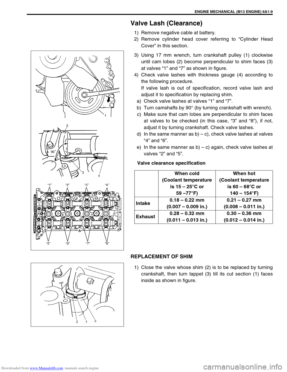
Valve Lash (Clearance)
1) Remove negative cable at battery.
2) Remove cylinder head cover referring to “Cylinder Head
Cover” in this section.
3) Using 17 mm wrench, turn crankshaft pulley (1) clockwise
until cam lobes (2) become perpendicular to shim faces (3)
at valves “1” and “7” as shown in figure.
4) Check valve lashes with thickness gauge (4) according to
the following procedure.
If valve lash is out of specification, record valve lash and
adjust it to specification by replacing shim.
a) Check valve lashes at valves “1” and “7”.
b) Turn camshafts by 90° (by turning crankshaft with wrench).
c) Make sure that cam lobes are perpendicular to shim faces
at valves to be checked (in this case, “3” and “8”), if not,
adjust it by turning crankshaft. Check valve lashes.
d) In the same manner as b) – c), check valve lashes at valves
“4” and “6”.
e) In the same manner as b) – c) again, check valve lashes at
valves “2” and “5”.
Valve clearance specification
REPLACEMENT OF SHIM
1) Close the valve whose shim (2) is to be replaced by turning
crankshaft, then turn tappet (3) till its cut section (1) faces
inside as shown in figure.When cold
(Coolant temperature
is 15 – 25°C or
59 –77°F)When hot
(Coolant temperature
is 60 – 68°C or
140 – 154°F)
Intake0.18 – 0.22 mm
(0.007 – 0.009 in.)0.21 – 0.27 mm
(0.008 – 0.011 in.)
Exhaust0.28 – 0.32 mm
(0.011 – 0.013 in.)0.30 – 0.36 mm
(0.012 – 0.014 in.)
Page 528 of 687

Downloaded from www.Manualslib.com manuals search engine ENGINE MECHANICAL (M13 ENGINE) 6A1-47
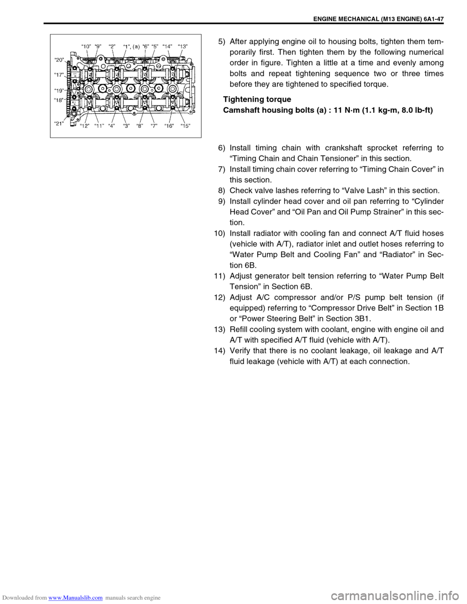
5) After applying engine oil to housing bolts, tighten them tem-
porarily first. Then tighten them by the following numerical
order in figure. Tighten a little at a time and evenly among
bolts and repeat tightening sequence two or three times
before they are tightened to specified torque.
Tightening torque
Camshaft housing bolts (a) : 11 N·m (1.1 kg-m, 8.0 lb-ft)
6) Install timing chain with crankshaft sprocket referring to
“Timing Chain and Chain Tensioner” in this section.
7) Install timing chain cover referring to “Timing Chain Cover” in
this section.
8) Check valve lashes referring to “Valve Lash” in this section.
9) Install cylinder head cover and oil pan referring to “Cylinder
Head Cover” and “Oil Pan and Oil Pump Strainer” in this sec-
tion.
10) Install radiator with cooling fan and connect A/T fluid hoses
(vehicle with A/T), radiator inlet and outlet hoses referring to
“Water Pump Belt and Cooling Fan” and “Radiator” in Sec-
tion 6B.
11) Adjust generator belt tension referring to “Water Pump Belt
Tension” in Section 6B.
12) Adjust A/C compressor and/or P/S pump belt tension (if
equipped) referring to “Compressor Drive Belt” in Section 1B
or “Power Steering Belt” in Section 3B1.
13) Refill cooling system with coolant, engine with engine oil and
A/T with specified A/T fluid (vehicle with A/T).
14) Verify that there is no coolant leakage, oil leakage and A/T
fluid leakage (vehicle with A/T) at each connection.
Page 620 of 687

Downloaded from www.Manualslib.com manuals search engine ENGINE AND EMISSION CONTROL SYSTEM 6E-15
On-Vehicle Service
Accelerator cable adjustment
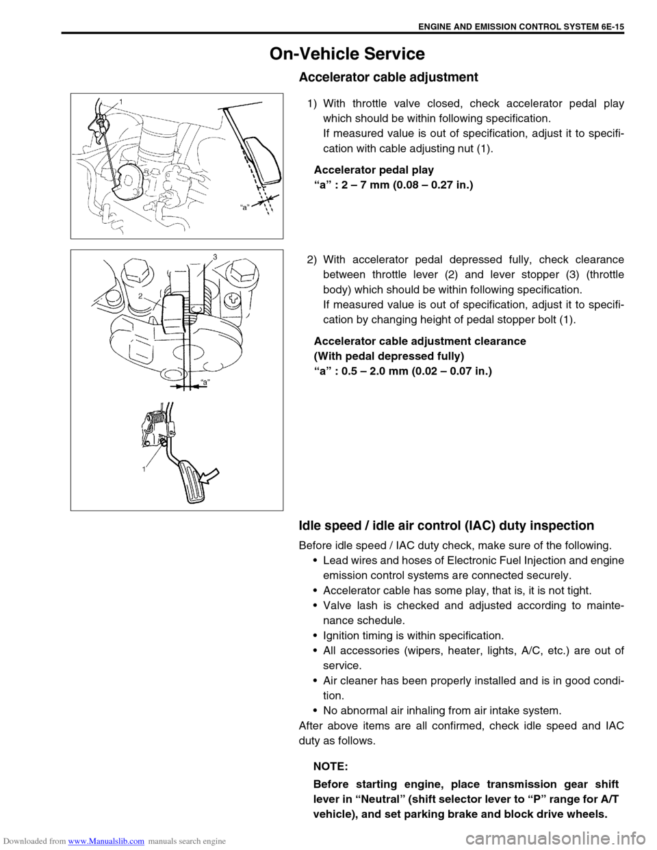
1) With throttle valve closed, check accelerator pedal play
which should be within following specification.
If measured value is out of specification, adjust it to specifi-
cation with cable adjusting nut (1).
Accelerator pedal play
“a” : 2 – 7 mm (0.08 – 0.27 in.)
2) With accelerator pedal depressed fully, check clearance
between throttle lever (2) and lever stopper (3) (throttle
body) which should be within following specification.
If measured value is out of specification, adjust it to specifi-
cation by changing height of pedal stopper bolt (1).
Accelerator cable adjustment clearance
(With pedal depressed fully)
“a” : 0.5 – 2.0 mm (0.02 – 0.07 in.)
Idle speed / idle air control (IAC) duty inspection
Before idle speed / IAC duty check, make sure of the following.
Lead wires and hoses of Electronic Fuel Injection and engine
emission control systems are connected securely.
Accelerator cable has some play, that is, it is not tight.
Valve lash is checked and adjusted according to mainte-
nance schedule.
Ignition timing is within specification.
All accessories (wipers, heater, lights, A/C, etc.) are out of
service.
Air cleaner has been properly installed and is in good condi-
tion.
No abnormal air inhaling from air intake system.
After above items are all confirmed, check idle speed and IAC
duty as follows.
NOTE:
Before starting engine, place transmission gear shift
lever in “Neutral” (shift selector lever to “P” range for A/T
vehicle), and set parking brake and block drive wheels.