compression SUZUKI JIMNY 2005 3.G Service User Guide
[x] Cancel search | Manufacturer: SUZUKI, Model Year: 2005, Model line: JIMNY, Model: SUZUKI JIMNY 2005 3.GPages: 687, PDF Size: 13.38 MB
Page 485 of 687
Downloaded from www.Manualslib.com manuals search engine 6A1-4 ENGINE MECHANICAL (M13 ENGINE)
Diagnosis
Diagnosis Table
Refer to “Engine Diagnosis Table” in Section 6.
Compression Check
Check compression pressure on all 4 cylinders as follows:
1) Warm up engine.
2) Stop engine after warming up.
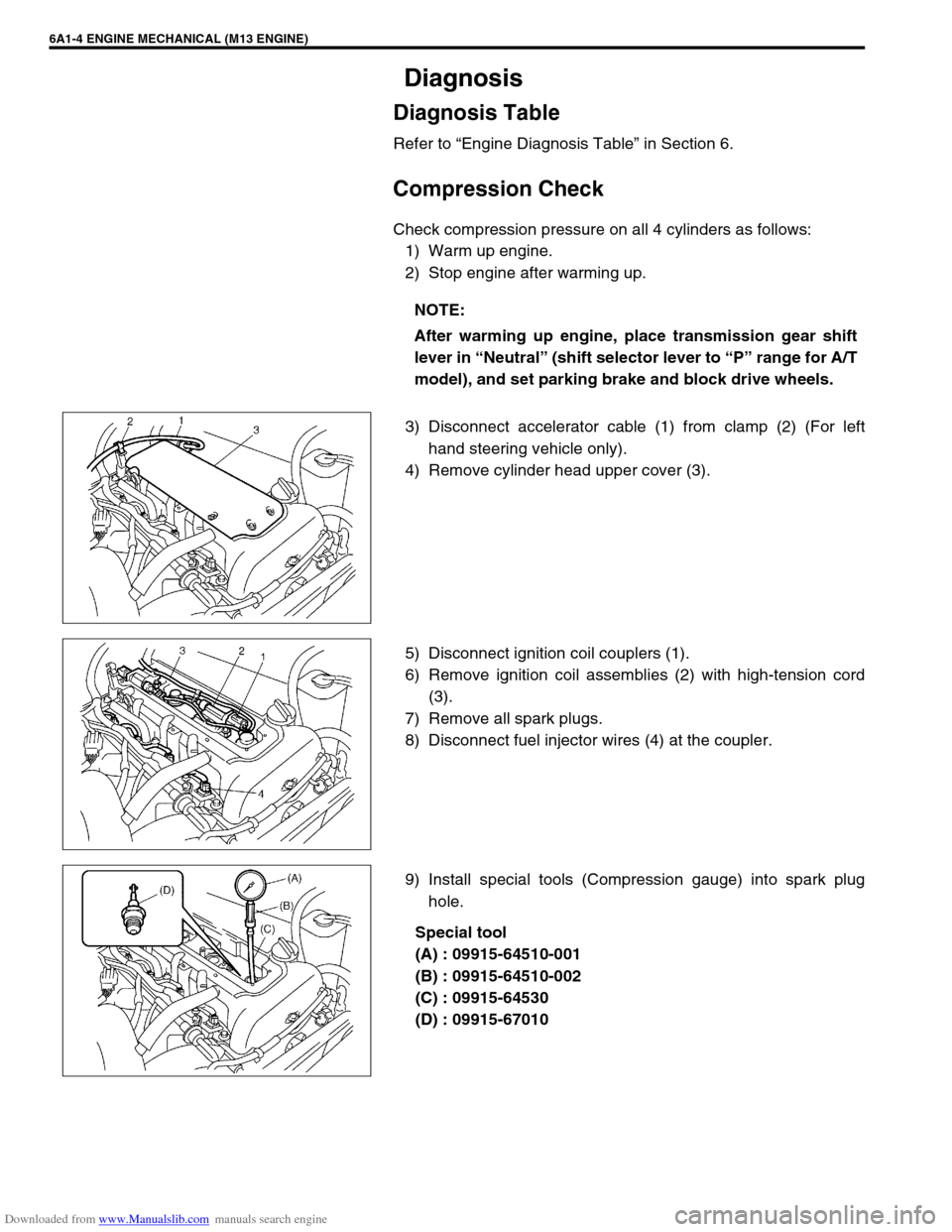
3) Disconnect accelerator cable (1) from clamp (2) (For left
hand steering vehicle only).
4) Remove cylinder head upper cover (3).
5) Disconnect ignition coil couplers (1).
6) Remove ignition coil assemblies (2) with high-tension cord
(3).
7) Remove all spark plugs.
8) Disconnect fuel injector wires (4) at the coupler.
9) Install special tools (Compression gauge) into spark plug
hole.
Special tool
(A) : 09915-64510-001
(B) : 09915-64510-002
(C) : 09915-64530
(D) : 09915-67010 NOTE:
After warming up engine, place transmission gear shift
lever in “Neutral” (shift selector lever to “P” range for A/T
model), and set parking brake and block drive wheels.
Page 486 of 687
Downloaded from www.Manualslib.com manuals search engine ENGINE MECHANICAL (M13 ENGINE) 6A1-5
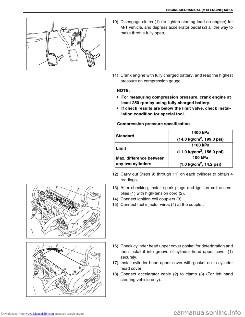
10) Disengage clutch (1) (to lighten starting load on engine) for
M/T vehicle, and depress accelerator pedal (2) all the way to
make throttle fully open.
11) Crank engine with fully charged battery, and read the highest
pressure on compression gauge.
Compression pressure specification
12) Carry out Steps 9) through 11) on each cylinder to obtain 4
readings.
13) After checking, install spark plugs and ignition coil assem-
blies (1) with high-tension cord (2).
14) Connect ignition coil couplers (3).
15) Connect fuel injector wires (4) at the coupler.
16) Check cylinder head upper cover gasket for deterioration and
then install it into groove of cylinder head upper cover (1)
securely.
17) Install cylinder head upper cover with gasket on to cylinder
head cover.
18) Connect accelerator cable (2) to clamp (3) (For left hand
steering vehicle only).
NOTE:
For measuring compression pressure, crank engine at
least 250 rpm by using fully charged battery.
If check results are below the limit valve, check instal-
lation condition for special tool.
Standard1400 kPa
(14.0 kg/cm
2, 199.0 psi)
Limit1100 kPa
(11.0 kg/cm
2, 156.0 psi)
Max. difference between
any two cylinders100 kPa
(1.0 kg/cm
2, 14.2 psi)
Page 544 of 687
Downloaded from www.Manualslib.com manuals search engine ENGINE MECHANICAL (M13 ENGINE) 6A1-63
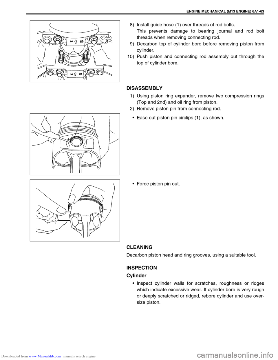
8) Install guide hose (1) over threads of rod bolts.
This prevents damage to bearing journal and rod bolt
threads when removing connecting rod.
9) Decarbon top of cylinder bore before removing piston from
cylinder.
10) Push piston and connecting rod assembly out through the
top of cylinder bore.
DISASSEMBLY
1) Using piston ring expander, remove two compression rings
(Top and 2nd) and oil ring from piston.
2) Remove piston pin from connecting rod.
Ease out piston pin circlips (1), as shown.
Force piston pin out.
CLEANING
Decarbon piston head and ring grooves, using a suitable tool.
INSPECTION
Cylinder
Inspect cylinder walls for scratches, roughness or ridges
which indicate excessive wear. If cylinder bore is very rough
or deeply scratched or ridged, rebore cylinder and use over-
size piston.
Page 575 of 687
Downloaded from www.Manualslib.com manuals search engine 6A1-94 ENGINE MECHANICAL (M13 ENGINE)
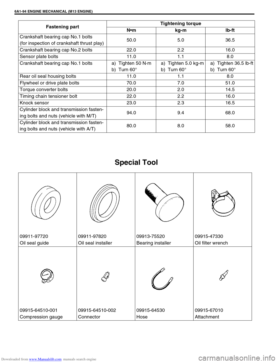
Special Tool
Crankshaft bearing cap No.1 bolts
(for inspection of crankshaft thrust play)50.0 5.0 36.5
Crankshaft bearing cap No.2 bolts 22.0 2.2 16.0
Sensor plate bolts 11.0 1.1 8.0
Crankshaft bearing cap No.1 bolts a) Tighten 50 N·m
b) Turn 60°a) Tighten 5.0 kg-m
b) Turn 60°a) Tighten 36.5 lb-ft
b) Turn 60°
Rear oil seal housing bolts 11.0 1.1 8.0
Flywheel or drive plate bolts 70.0 7.0 51.0
Torque converter bolts 20.0 2.0 14.5
Timing chain tensioner bolt 22.0 2.2 16.0
Knock sensor 23.0 2.3 16.5
Cylinder block and transmission fasten-
ing bolts and nuts (vehicle with M/T)94.0 9.4 68.0
Cylinder block and transmission fasten-
ing bolts and nuts (vehicle with A/T)80.0 8.0 58.0 Fastening partTightening torque
Nm kg-m lb-ft
09911-97720 09911-97820 09913-75520 09915-47330
Oil seal guide Oil seal installer Bearing installer Oil filter wrench
09915-64510-001 09915-64510-002 09915-64530 09915-67010
Compression gauge Connector Hose Attachment
Page 651 of 687
Downloaded from www.Manualslib.com manuals search engine 6F-2 IGNITION SYSTEM (ELECTRONIC IGNITION SYSTEM)
General Description
The ignition system is an electronic (distributorless) ignition system. It consists of the parts as described below
and has an electronic ignition control system.
ECM
It detects the engine and vehicle conditions through the signals from the sensors, determines the most suit-
able ignition timing and time for electricity to flow to the primary coil and sends a signal to the ignitor (power
unit) in the ignition coil assembly.
Ignition coil assembly (including an ignitor)
The ignition coil assembly has a built-in ignitor which turns ON and OFF the current flow to the primary coil
according to the signal from ECM. When the current flow to the primary coil is turned OFF, a high voltage is
induced in the secondary coil.
High tension cords and spark plugs.
CMP sensor (Camshaft position sensor) and CKP sensor (Crankshaft position sensor)
Using signals from these sensors, ECM identifies the specific cylinder whose piston is in the compression
stroke, detects the crank angle and adjust initial ignition timing automatically.
TP sensor, ECT sensor, MAP sensor and other sensors/switches
Refer to “Electronic Control System” in Section 6E for details.
Although this ignition system does not have a distributor, it has two ignition coil assemblies (one is for No.1 and
No.4 spark plugs and the other is for No.2 and No.3 spark plugs). When an ignition signal is sent from ECM to
the ignitor in the ignition coil assembly for No.1 and No.4 spark plugs, a high voltage is induced in the secondary
coil and that passes through the high-tension cords and causes No.1 and No.4 spark plugs to spark simulta-
neously. Likewise, when an ignition signal is sent to the ignitor in the other ignition coil assembly, No.2 and No.3
spark plugs spark simultaneously.
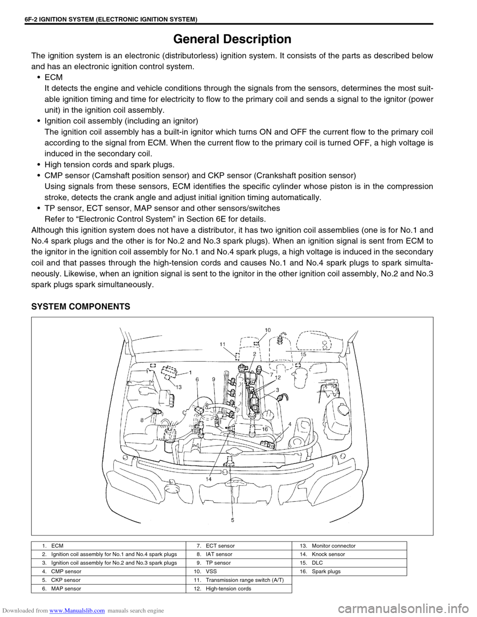
SYSTEM COMPONENTS
1. ECM 7. ECT sensor 13. Monitor connector
2. Ignition coil assembly for No.1 and No.4 spark plugs 8. IAT sensor 14. Knock sensor
3. Ignition coil assembly for No.2 and No.3 spark plugs 9. TP sensor 15. DLC
4. CMP sensor 10. VSS 16. Spark plugs
5. CKP sensor 11. Transmission range switch (A/T)
6. MAP sensor 12. High-tension cords