radiator SUZUKI JIMNY 2005 3.G Service User Guide
[x] Cancel search | Manufacturer: SUZUKI, Model Year: 2005, Model line: JIMNY, Model: SUZUKI JIMNY 2005 3.GPages: 687, PDF Size: 13.38 MB
Page 149 of 687
Downloaded from www.Manualslib.com manuals search engine 3B1-18 POWER STEERING (P/S) SYSTEM (If equipped)
INSTALLATION
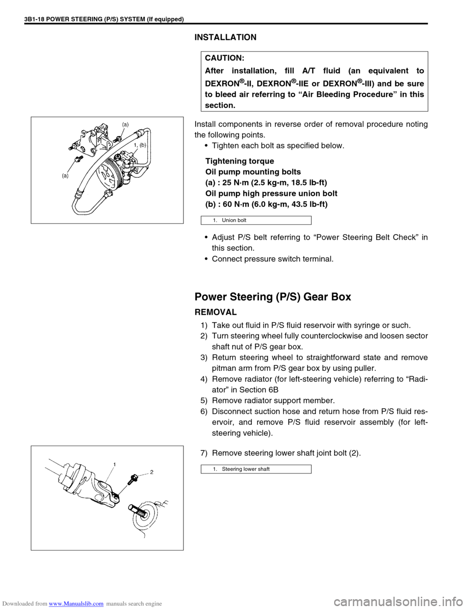
Install components in reverse order of removal procedure noting
the following points.
Tighten each bolt as specified below.
Tightening torque
Oil pump mounting bolts
(a) : 25 N·m (2.5 kg-m, 18.5 lb-ft)
Oil pump high pressure union bolt
(b) : 60 N·m (6.0 kg-m, 43.5 lb-ft)
Adjust P/S belt referring to “Power Steering Belt Check” in
this section.
Connect pressure switch terminal.
Power Steering (P/S) Gear Box
REMOVAL
1) Take out fluid in P/S fluid reservoir with syringe or such.
2) Turn steering wheel fully counterclockwise and loosen sector
shaft nut of P/S gear box.
3) Return steering wheel to straightforward state and remove
pitman arm from P/S gear box by using puller.
4) Remove radiator (for left-steering vehicle) referring to “Radi-
ator” in Section 6B
5) Remove radiator support member.
6) Disconnect suction hose and return hose from P/S fluid res-
ervoir, and remove P/S fluid reservoir assembly (for left-
steering vehicle).
7) Remove steering lower shaft joint bolt (2).CAUTION:
After installation, fill A/T fluid (an equivalent to
DEXRON
®-II, DEXRON®-IIE or DEXRON®-III) and be sure
to bleed air referring to “Air Bleeding Procedure” in this
section.
1. Union bolt
1. Steering lower shaft
Page 151 of 687
Downloaded from www.Manualslib.com manuals search engine 3B1-20 POWER STEERING (P/S) SYSTEM (If equipped)
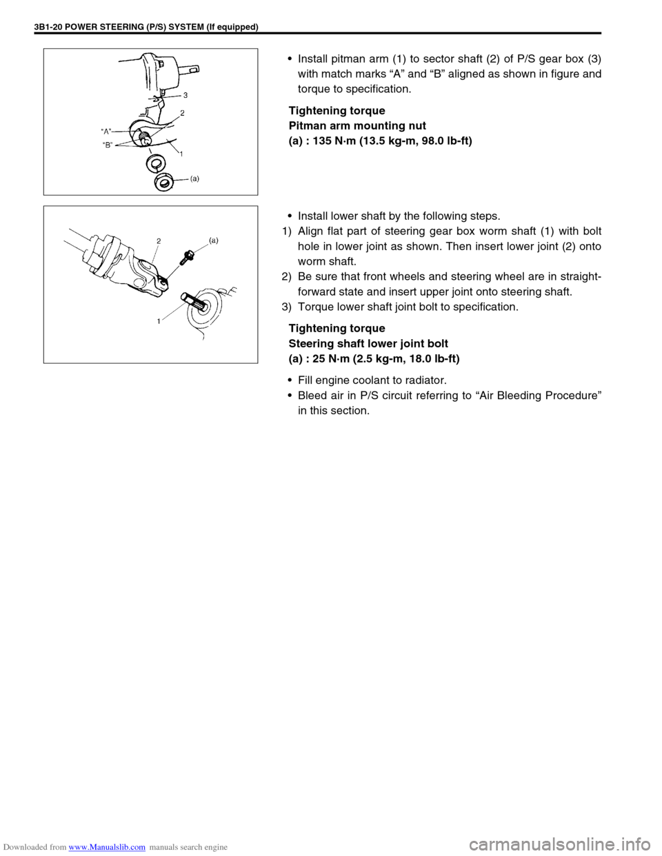
Install pitman arm (1) to sector shaft (2) of P/S gear box (3)
with match marks “A” and “B” aligned as shown in figure and
torque to specification.
Tightening torque
Pitman arm mounting nut
(a) : 135 N·m (13.5 kg-m, 98.0 lb-ft)
Install lower shaft by the following steps.
1) Align flat part of steering gear box worm shaft (1) with bolt
hole in lower joint as shown. Then insert lower joint (2) onto
worm shaft.
2) Be sure that front wheels and steering wheel are in straight-
forward state and insert upper joint onto steering shaft.
3) Torque lower shaft joint bolt to specification.
Tightening torque
Steering shaft lower joint bolt
(a) : 25 N·m (2.5 kg-m, 18.0 lb-ft)
Fill engine coolant to radiator.
Bleed air in P/S circuit referring to “Air Bleeding Procedure”
in this section.
Page 382 of 687

Downloaded from www.Manualslib.com manuals search engine ENGINE GENERAL INFORMATION AND DIAGNOSIS 6-25
Excessive detonation
(The engine makes
sharp metallic knocks
that change with throt-
tle opening.
Sounds like pop corn
popping.)Engine overheating Refer to “Overheating” of this table.
Faulty spark plug Spark plugs in Section 6F.
Clogged fuel filter and fuel lines Diagnostic Flow Table B-3
Malfunctioning EGR valve (if equipped) EGR system in Section 6E.
Poor performance of knock sensor, ECT
sensor or MAP sensorKnock sensor in this section, ECT
sensor or MAP sensor in Section 6E.
Faulty injector Diagnostic Flow Table B-1
Faulty ECM Inspection of ECM and its circuit in
this section.
Excessive combustion chamber deposits Piston and cylinder head in Section
6A1.
Overheating
Inoperative thermostat Thermostat in Section 6B.
Faulty A/C condenser fan motor or its cir-
cuitA/C condenser fan control system
check in Section 6E.
Loose or slip water pump belt ITEM1-1 Drive belt inspection and
change in Section 0B.
Poor water pump performance Water pump in Section 6B.
Clogged or leaky radiator Radiator in Section 6B.
Improper engine oil grade ITEM1-3 Engine oil and oil filter
change in Section 0B.
Clogged oil filter or oil strainer Oil pressure check in Section 6A1.
Poor oil pump performance Oil pressure check in Section 6A1.
Dragging brakes Diagnosis Table in Section 5.
Slipping clutch Diagnosis Table in Section 7C.
Blown cylinder head gasket Valves and cylinder head in Section
6A1.
Poor gasoline mileage
Faulty ignition coil Ignition coil assembly in Section 6F.
Fuel pressure out of specification Diagnostic Flow Table B-3
Faulty TP sensor, ECT sensor or MAP
sensorTP sensor, ECT sensor or MAP sen-
sor in Section 6E.
Faulty injector Diagnostic Flow Table B-1
Faulty ECM Inspection of ECM and its circuit in
this section.
Malfunctioning EGR valve (if equipped) EGR system in Section 6E.
High idle speed Refer to item “Improper Engine Idle
Speed” previously outlined.
Low compression Previously outlined.
Poor valve seating Valves and cylinder head in Section
6A1.
Dragging brakes Diagnosis Table in Section 5.
Slipping clutch Diagnosis Table in Section 7C.
Thermostat out of order Thermostat in Section 6B.
Improper tire pressure Refer to Section 3F. Condition Possible Cause Reference Item
Page 499 of 687
Downloaded from www.Manualslib.com manuals search engine 6A1-18 ENGINE MECHANICAL (M13 ENGINE)
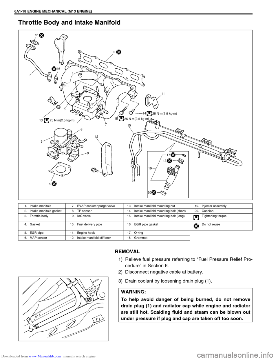
Throttle Body and Intake Manifold
REMOVAL
1) Relieve fuel pressure referring to “Fuel Pressure Relief Pro-
cedure” in Section 6.
2) Disconnect negative cable at battery.
3) Drain coolant by loosening drain plug (1).
1. Intake manifold 7. EVAP canister purge valve 13. Intake manifold mounting nut 19. Injector assembly
2. Intake manifold gasket 8. TP sensor 14. Intake manifold mounting bolt (short) 20. Cushion
3. Throttle body 9. IAC valve 15. Intake manifold mounting bolt (long) Tightening torque
4. Gasket 10. Fuel delivery pipe 16. EGR pipe gasket Do not reuse
5. EGR pipe 11. Engine hook 17. O-ring
6. MAP sensor 12. Intake manifold stiffener 18. Grommet
WARNING:
To help avoid danger of being burned, do not remove
drain plug (1) and radiator cap while engine and radiator
are still hot. Scalding fluid and steam can be blown out
under pressure if plug and cap are taken off too soon.
Page 510 of 687
Downloaded from www.Manualslib.com manuals search engine ENGINE MECHANICAL (M13 ENGINE) 6A1-29
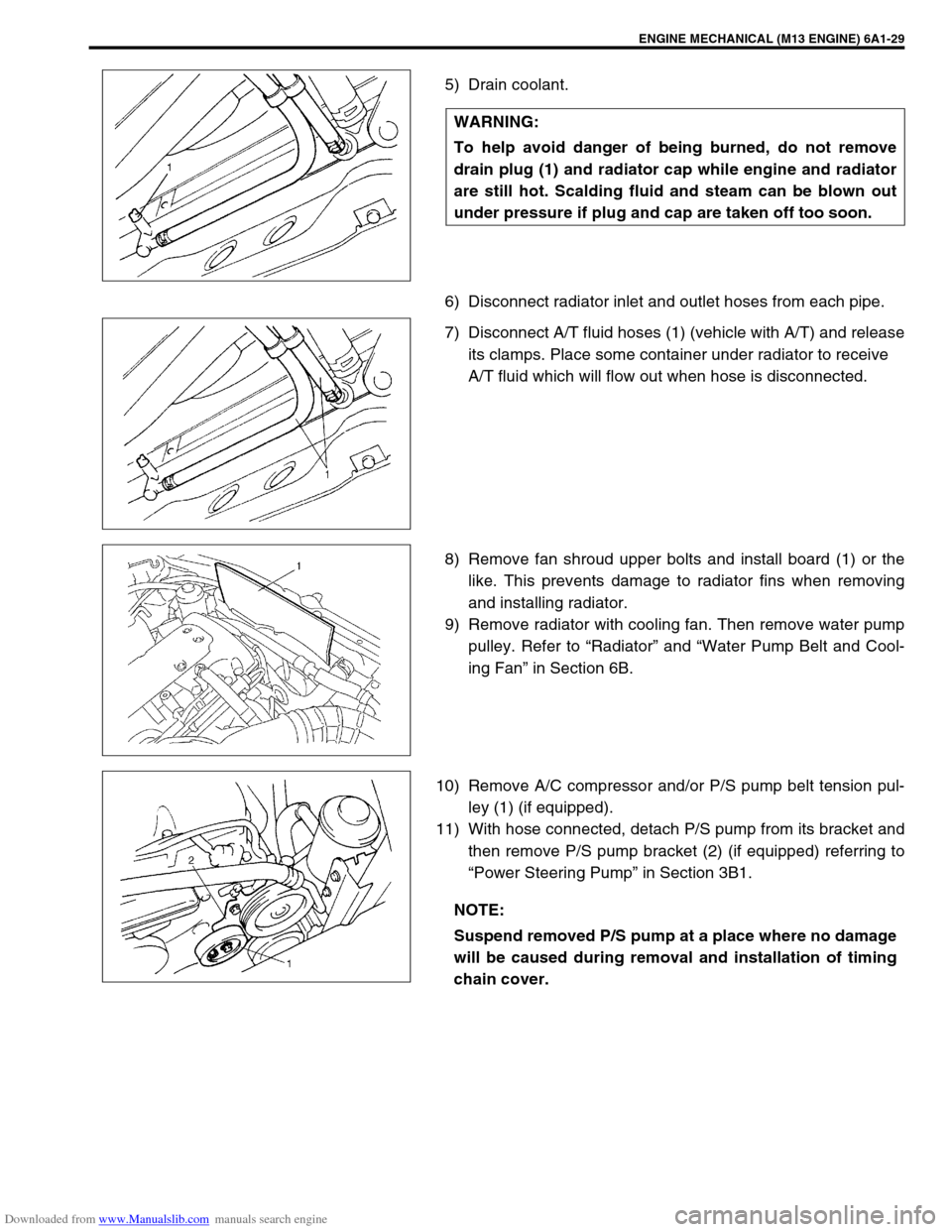
5) Drain coolant.
6) Disconnect radiator inlet and outlet hoses from each pipe.
7) Disconnect A/T fluid hoses (1) (vehicle with A/T) and release
its clamps. Place some container under radiator to receive
A/T fluid which will flow out when hose is disconnected.
8) Remove fan shroud upper bolts and install board (1) or the
like. This prevents damage to radiator fins when removing
and installing radiator.
9) Remove radiator with cooling fan. Then remove water pump
pulley. Refer to “Radiator” and “Water Pump Belt and Cool-
ing Fan” in Section 6B.
10) Remove A/C compressor and/or P/S pump belt tension pul-
ley (1) (if equipped).
11) With hose connected, detach P/S pump from its bracket and
then remove P/S pump bracket (2) (if equipped) referring to
“Power Steering Pump” in Section 3B1. WARNING:
To help avoid danger of being burned, do not remove
drain plug (1) and radiator cap while engine and radiator
are still hot. Scalding fluid and steam can be blown out
under pressure if plug and cap are taken off too soon.
NOTE:
Suspend removed P/S pump at a place where no damage
will be caused during removal and installation of timing
chain cover.
Page 513 of 687
Downloaded from www.Manualslib.com manuals search engine 6A1-32 ENGINE MECHANICAL (M13 ENGINE)
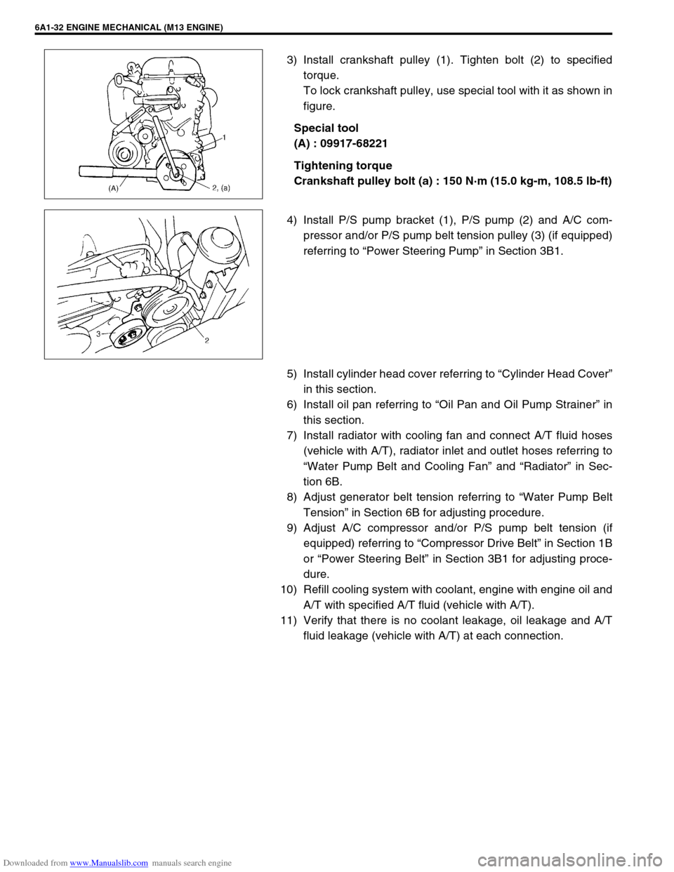
3) Install crankshaft pulley (1). Tighten bolt (2) to specified
torque.
To lock crankshaft pulley, use special tool with it as shown in
figure.
Special tool
(A) : 09917-68221
Tightening torque
Crankshaft pulley bolt (a) : 150 N·m (15.0 kg-m, 108.5 lb-ft)
4) Install P/S pump bracket (1), P/S pump (2) and A/C com-
pressor and/or P/S pump belt tension pulley (3) (if equipped)
referring to “Power Steering Pump” in Section 3B1.
5) Install cylinder head cover referring to “Cylinder Head Cover”
in this section.
6) Install oil pan referring to “Oil Pan and Oil Pump Strainer” in
this section.
7) Install radiator with cooling fan and connect A/T fluid hoses
(vehicle with A/T), radiator inlet and outlet hoses referring to
“Water Pump Belt and Cooling Fan” and “Radiator” in Sec-
tion 6B.
8) Adjust generator belt tension referring to “Water Pump Belt
Tension” in Section 6B for adjusting procedure.
9) Adjust A/C compressor and/or P/S pump belt tension (if
equipped) referring to “Compressor Drive Belt” in Section 1B
or “Power Steering Belt” in Section 3B1 for adjusting proce-
dure.
10) Refill cooling system with coolant, engine with engine oil and
A/T with specified A/T fluid (vehicle with A/T).
11) Verify that there is no coolant leakage, oil leakage and A/T
fluid leakage (vehicle with A/T) at each connection.
Page 528 of 687
Downloaded from www.Manualslib.com manuals search engine ENGINE MECHANICAL (M13 ENGINE) 6A1-47
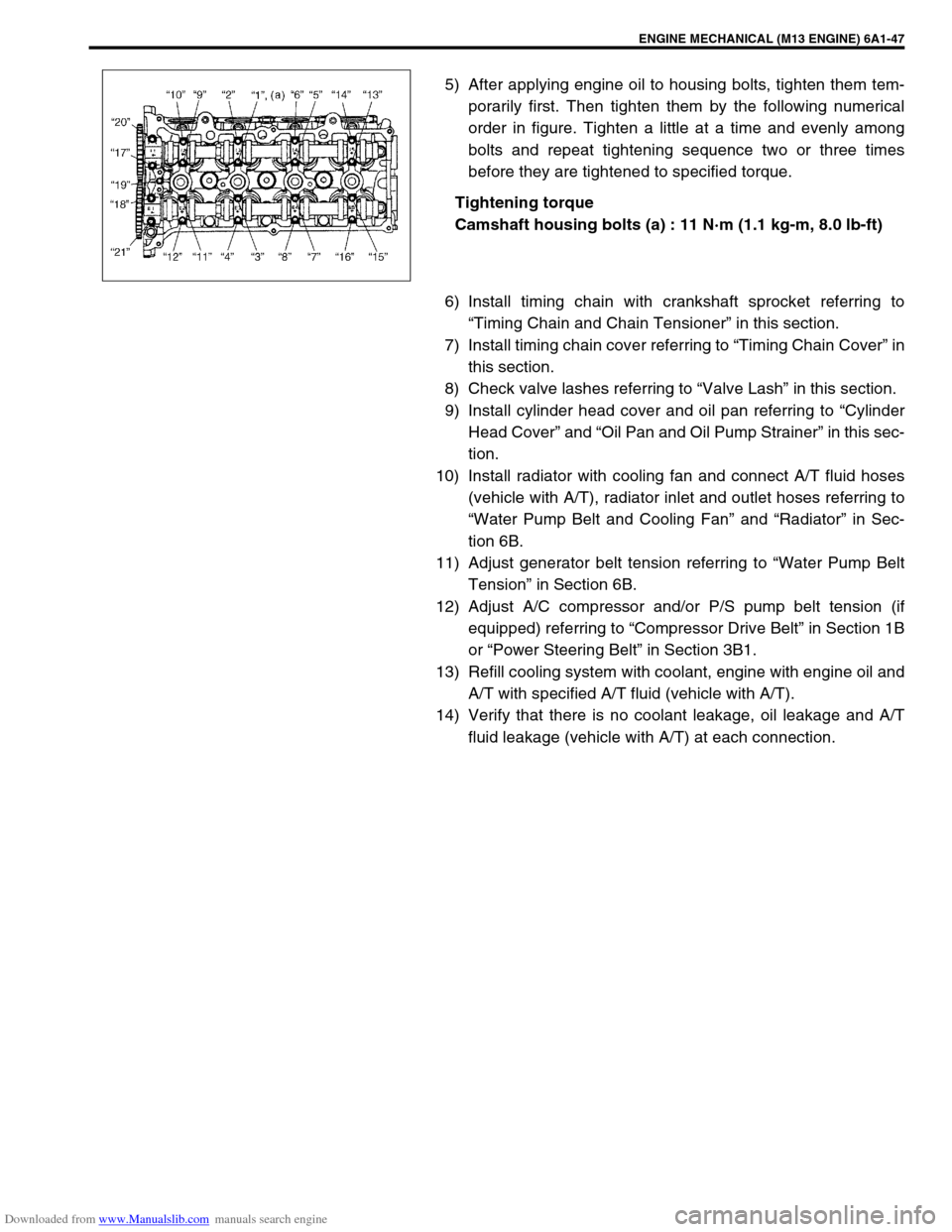
5) After applying engine oil to housing bolts, tighten them tem-
porarily first. Then tighten them by the following numerical
order in figure. Tighten a little at a time and evenly among
bolts and repeat tightening sequence two or three times
before they are tightened to specified torque.
Tightening torque
Camshaft housing bolts (a) : 11 N·m (1.1 kg-m, 8.0 lb-ft)
6) Install timing chain with crankshaft sprocket referring to
“Timing Chain and Chain Tensioner” in this section.
7) Install timing chain cover referring to “Timing Chain Cover” in
this section.
8) Check valve lashes referring to “Valve Lash” in this section.
9) Install cylinder head cover and oil pan referring to “Cylinder
Head Cover” and “Oil Pan and Oil Pump Strainer” in this sec-
tion.
10) Install radiator with cooling fan and connect A/T fluid hoses
(vehicle with A/T), radiator inlet and outlet hoses referring to
“Water Pump Belt and Cooling Fan” and “Radiator” in Sec-
tion 6B.
11) Adjust generator belt tension referring to “Water Pump Belt
Tension” in Section 6B.
12) Adjust A/C compressor and/or P/S pump belt tension (if
equipped) referring to “Compressor Drive Belt” in Section 1B
or “Power Steering Belt” in Section 3B1.
13) Refill cooling system with coolant, engine with engine oil and
A/T with specified A/T fluid (vehicle with A/T).
14) Verify that there is no coolant leakage, oil leakage and A/T
fluid leakage (vehicle with A/T) at each connection.
Page 530 of 687
Downloaded from www.Manualslib.com manuals search engine ENGINE MECHANICAL (M13 ENGINE) 6A1-49
REMOVAL
1) Relieve fuel pressure referring to “Fuel Pressure Relief Pro-
cedure” in Section 6.
2) Disconnect negative cable at battery.
3) Drain engine oil.
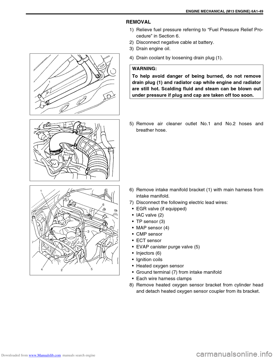
4) Drain coolant by loosening drain plug (1).
5) Remove air cleaner outlet No.1 and No.2 hoses and
breather hose.
6) Remove intake manifold bracket (1) with main harness from
intake manifold.
7) Disconnect the following electric lead wires:
EGR valve (if equipped)
IAC valve (2)
TP sensor (3)
MAP sensor (4)
CMP sensor
ECT sensor
EVAP canister purge valve (5)
Injectors (6)
Ignition coils
Heated oxygen sensor
Ground terminal (7) from intake manifold
Each wire harness clamps
8) Remove heated oxygen sensor bracket from cylinder head
and detach heated oxygen sensor coupler from its bracket. WARNING:
To help avoid danger of being burned, do not remove
drain plug (1) and radiator cap while engine and radiator
are still hot. Scalding fluid and steam can be blown out
under pressure if plug and cap are taken off too soon.
Page 542 of 687

Downloaded from www.Manualslib.com manuals search engine ENGINE MECHANICAL (M13 ENGINE) 6A1-61
6) Install exhaust manifold stiffener and exhaust pipe referring
to “Exhaust Manifold” in this section.
7) Install camshafts, timing chain and chain cover referring to
“Camshaft, Tappet and Shim”, “Timing Chain and Chain
Tensioner” and “Timing Chain Cover” in this section.
8) Install cylinder head cover and oil pan referring to “Cylinder
Head Cover” and “Oil Pan and Oil Pump Strainer” in this sec-
tion.
9) Install intake manifold stiffener and connect each hoses and
electric lead wires securely.
10) Install air cleaner outlet hoses.
11) Install radiator with cooling fan and connect A/T fluid hoses
(vehicle with A/T), radiator inlet and outlet hoses referring to
“Water Pump Belt and Cooling Fan” and “Radiator” in Sec-
tion 6B.
12) Adjust generator belt tension referring to “Water Pump Belt
Tension” in Section 6B.
13) Adjust A/C compressor and/or P/S pump belt tension (if
equipped) referring to “Compressor Drive Belt” in Section 1B
or “Power Steering Belt” in Section 3B1.
14) Adjust accelerator cable play referring to “Accelerator Cable
Adjustment” in Section 6E.
15) Check to ensure that all removed parts are back in place.
Reinstall any necessary parts which have not been rein-
stalled.
16) Refill cooling system with coolant, engine with engine oil and
A/T with specified A/T fluid (vehicle with A/T).
17) Connect negative cable at battery.
18) Verify that there is no fuel leakage, coolant leakage, oil leak-
age, A/T fluid leakage (vehicle with A/T) and exhaust gas
leakage at each connection.
Page 554 of 687
Downloaded from www.Manualslib.com manuals search engine ENGINE MECHANICAL (M13 ENGINE) 6A1-73
Unit Repair Overhaul
Engine Assembly
REMOVAL
1) Relieve fuel pressure referring to “Fuel Pressure Relief Pro-
cedure” in Section 6.
2) Disconnect negative cable at battery.
3) Remove engine hood after disconnecting windshield washer
hose.
4) Remove A/C compressor and/or P/S pump belt (if
equipped).
5) Remove generator belt.
6) Drain engine oil.
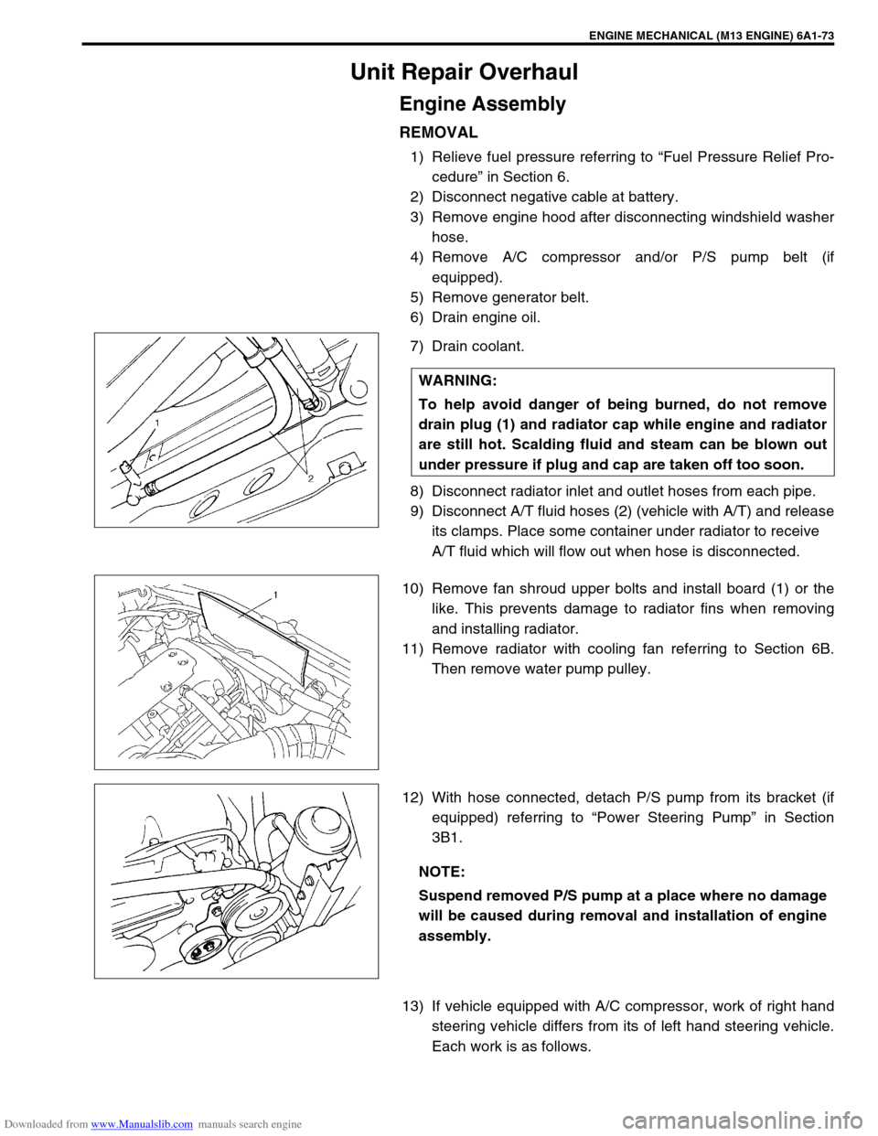
7) Drain coolant.
8) Disconnect radiator inlet and outlet hoses from each pipe.
9) Disconnect A/T fluid hoses (2) (vehicle with A/T) and release
its clamps. Place some container under radiator to receive
A/T fluid which will flow out when hose is disconnected.
10) Remove fan shroud upper bolts and install board (1) or the
like. This prevents damage to radiator fins when removing
and installing radiator.
11) Remove radiator with cooling fan referring to Section 6B.
Then remove water pump pulley.
12) With hose connected, detach P/S pump from its bracket (if
equipped) referring to “Power Steering Pump” in Section
3B1.
13) If vehicle equipped with A/C compressor, work of right hand
steering vehicle differs from its of left hand steering vehicle.
Each work is as follows. WARNING:
To help avoid danger of being burned, do not remove
drain plug (1) and radiator cap while engine and radiator
are still hot. Scalding fluid and steam can be blown out
under pressure if plug and cap are taken off too soon.
NOTE:
Suspend removed P/S pump at a place where no damage
will be caused during removal and installation of engine
assembly.