ECU SUZUKI JIMNY 2005 3.G Service Owner's Manual
[x] Cancel search | Manufacturer: SUZUKI, Model Year: 2005, Model line: JIMNY, Model: SUZUKI JIMNY 2005 3.GPages: 687, PDF Size: 13.38 MB
Page 282 of 687
Downloaded from www.Manualslib.com manuals search engine BRAKES 5-21
INSTALLATION
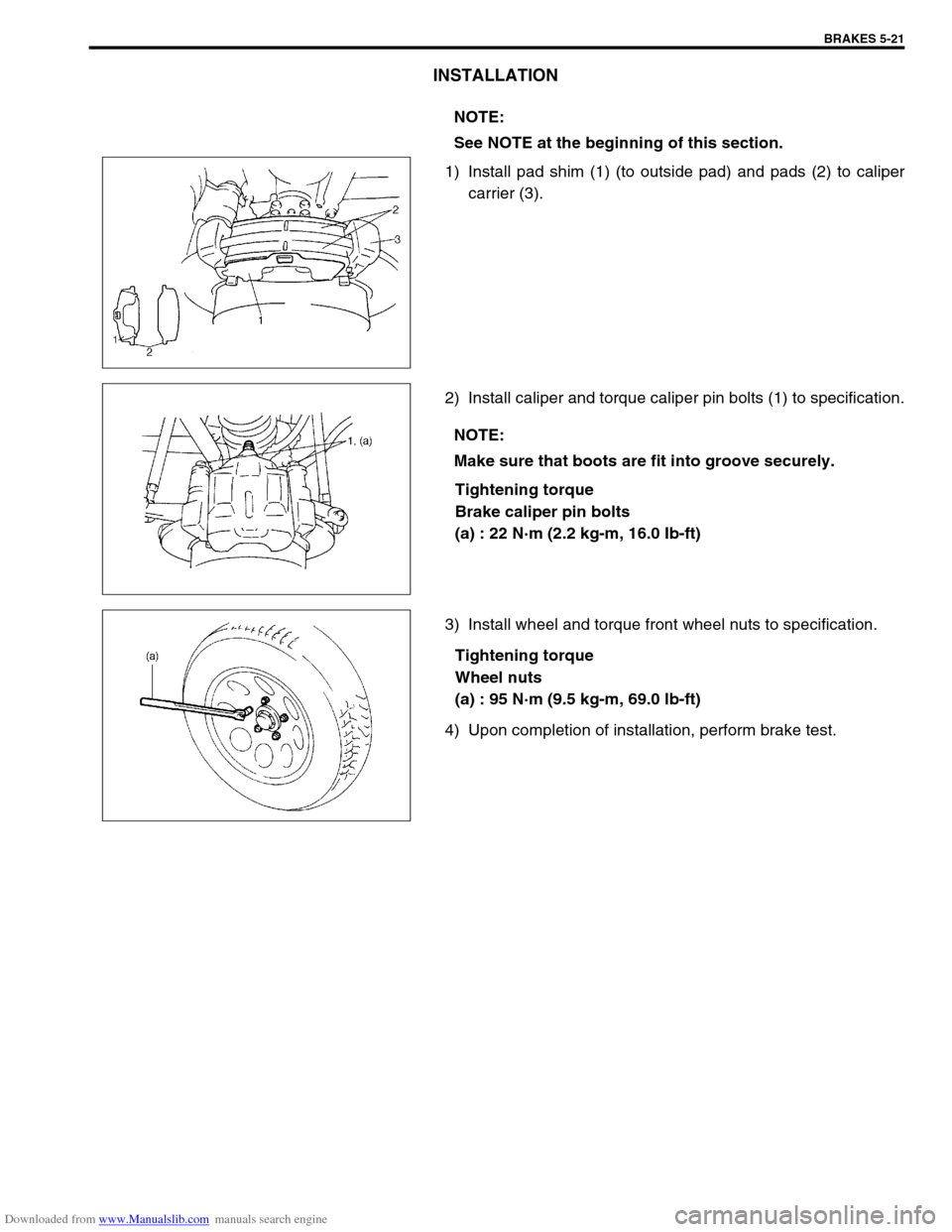
1) Install pad shim (1) (to outside pad) and pads (2) to caliper
carrier (3).
2) Install caliper and torque caliper pin bolts (1) to specification.
Tightening torque
Brake caliper pin bolts
(a) : 22 N·m (2.2 kg-m, 16.0 Ib-ft)
3) Install wheel and torque front wheel nuts to specification.
Tightening torque
Wheel nuts
(a) : 95 N·m (9.5 kg-m, 69.0 lb-ft)
4) Upon completion of installation, perform brake test.NOTE:
See NOTE at the beginning of this section.
NOTE:
Make sure that boots are fit into groove securely.
Page 286 of 687
Downloaded from www.Manualslib.com manuals search engine BRAKES 5-25
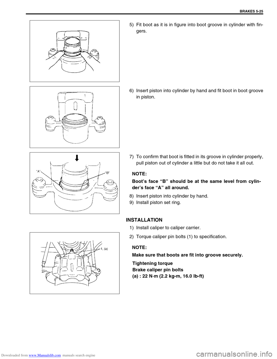
5) Fit boot as it is in figure into boot groove in cylinder with fin-
gers.
6) Insert piston into cylinder by hand and fit boot in boot groove
in piston.
7) To confirm that boot is fitted in its groove in cylinder properly,
pull piston out of cylinder a little but do not take it all out.
8) Insert piston into cylinder by hand.
9) Install piston set ring.
INSTALLATION
1) Install caliper to caliper carrier.
2) Torque caliper pin bolts (1) to specification.
Tightening torque
Brake caliper pin bolts
(a) : 22 N·m (2.2 kg-m, 16.0 lb-ft)
NOTE:
Boot’s face “B” should be at the same level from cylin-
der’s face “A” all around.
NOTE:
Make sure that boots are fit into groove securely.
Page 288 of 687
Downloaded from www.Manualslib.com manuals search engine BRAKES 5-27
INSPECTION
Check disc surface for scratches in wearing parts. Scratches on
disc surface noticed at the time of specified inspection or replace-
ment are normal and disc is not defective unless they are serious.
But when there are deep scratches or scratches all over disc sur-
face, replace it. When only one side is scratched, polish and cor-
rect that side.
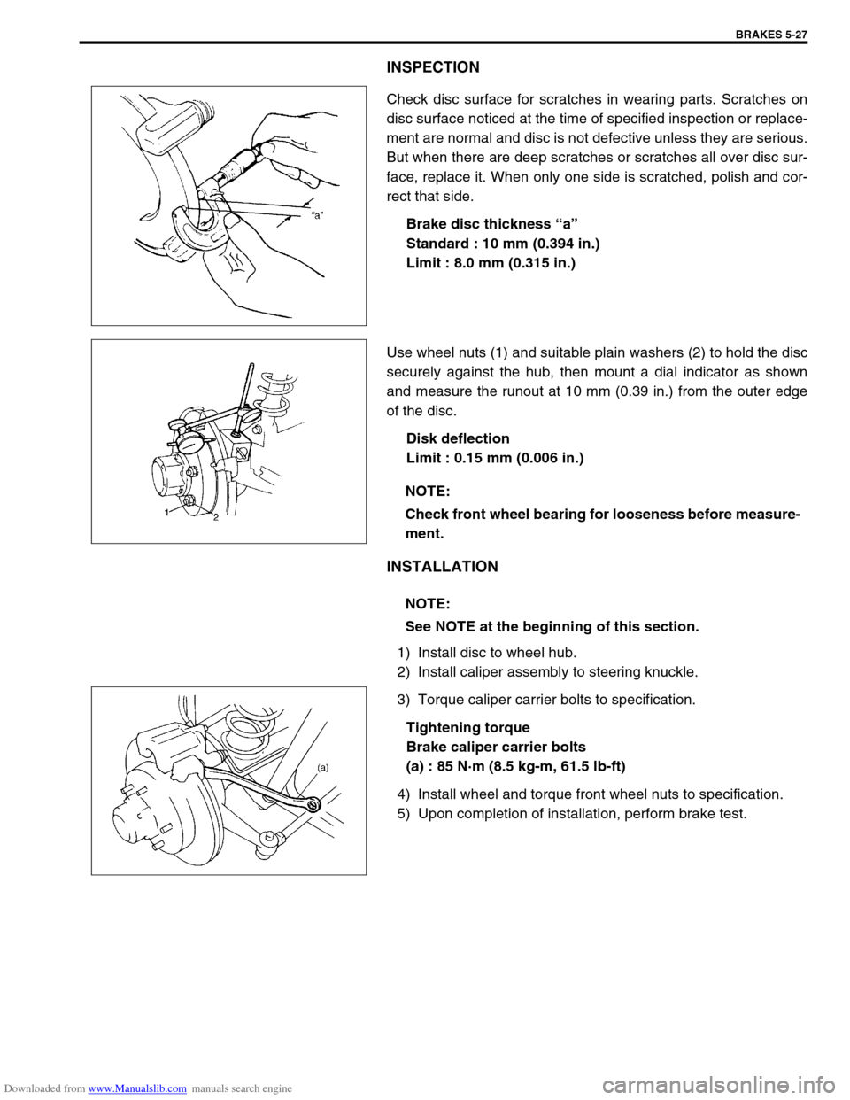
Brake disc thickness “a”
Standard : 10 mm (0.394 in.)
Limit : 8.0 mm (0.315 in.)
Use wheel nuts (1) and suitable plain washers (2) to hold the disc
securely against the hub, then mount a dial indicator as shown
and measure the runout at 10 mm (0.39 in.) from the outer edge
of the disc.
Disk deflection
Limit : 0.15 mm (0.006 in.)
INSTALLATION
1) Install disc to wheel hub.
2) Install caliper assembly to steering knuckle.
3) Torque caliper carrier bolts to specification.
Tightening torque
Brake caliper carrier bolts
(a) : 85 N·m (8.5 kg-m, 61.5 lb-ft)
4) Install wheel and torque front wheel nuts to specification.
5) Upon completion of installation, perform brake test.
NOTE:
Check front wheel bearing for looseness before measure-
ment.
NOTE:
See NOTE at the beginning of this section.
Page 323 of 687

Downloaded from www.Manualslib.com manuals search engine 5E-6 ANTILOCK BRAKE SYSTEM (ABS)
Diagnosis
To ensure that the trouble diagnosis is done accurately and smoothly, observe “Precautions in Diagnosing Trou-
bles” and follow “ABS Diagnostic Flow Table”.
Precaution in Diagnosing Troubles
If the vehicles was operated in any of the following ways, “ABS” warning lamp may light momentarily but this
does not indicate anything abnormal in ABS.
–The vehicle was driven with parking brake pulled.
–The vehicle was driven with brake dragging.
–The vehicle was stuck in mud, sand, etc.
–Wheel spin occurred while driving.
–Wheel(s) was rotated while the vehicle was jacked up.
Be sure to read “Precautions for Electronic Circuit Service” in Section 0A before inspection and observe
what is written there.
Be sure to use the trouble diagnosis procedure as described in the flow table. Failure to follow the flow table
may result in incorrect diagnosis. Some other diag. trouble code may be stored by mistake in the memory of
ABS control module during inspection.
ABS Diagnostic Flow Table
Refer to the following for the details of each step.
Step Action Yes No
1 Perform customer complaint analysis, problem symptom confir-
mation and diagnostic trouble code check record and clear-
ance.
Is there any trouble code?Go to Step 2. Go to Step 5.
2 Perform driving test.
Is trouble symptom identified?Go to Step 3. Go to Step 6.
3 Check diagnostic trouble code.
Is it malfunction code?Go to Step 4. Go to Step 5.
4 Inspect and repair referring to applicable diagnostic trouble
code table in this section. Then perform final confirmation test
after clearing diagnostic trouble code.
Is trouble recur?Go to Step 7. End.
5 Inspect and repair referring to “Diagnosis Table” in Section 5.
Then perform final confirmation test after clearing diagnostic
trouble code.
Is trouble recur?Go to Step 7. End.
6 Check for intermittent problems referring to “Intermittent and
Poor Connection” in Section 0A and related circuit of trouble
code recorded in Step 3. Then perform final confirmation test
after clearing diagnostic trouble code.
Is trouble recur?Go to Step 7. End.
7 Perform diagnostic trouble code check record and clearance.
Is there any trouble code?Go to Step 4. Go to Step 5.
Page 334 of 687

Downloaded from www.Manualslib.com manuals search engine ANTILOCK BRAKE SYSTEM (ABS) 5E-17
Table – D Code (DTC) is Not Outputted Even With Diag. Switch Terminal Con-
nected to Ground.
CIRCUIT DESCRIPTION
When the diag. switch terminal is connected to the ground with the ignition switch turned ON, the ABS control
module outputs a diagnostic trouble code by flashing “ABS” warning lamp.
INSPECTION
1.“ABS” warning lamp in combination meter 3-1. Diag. switch terminal 4-1. Lock position
2. ABS hydraulic unit / control module assembly 3-2. Diag. ground terminal 4-2. Unlock position
3. Monitor connector 4. ABS hydraulic unit / control module connector of harness
Step Action Yes No
1 Is it shorted diag. switch terminal and ground
terminal by service wire properly?Go to step 2. Connect service wire
securely.
2 1) Disconnect service wire.
2) Disconnect ABS hydraulic unit / control
module connector.
3) Measure resistance between diag. switch
terminal and connector terminal “A12”.
Is it infinite (∞)?“P/B” circuit open. Go to step 3.
3 1) Measure resistance between ground termi-
nal of monitor connector and body ground.
Is continuity indicated?Go to step 4.“B” circuit open or poor
connection.
4 1) Check for proper connection to ABS hydrau-
lic unit / control module at terminal “A12”
and “A24”.
2) If OK, then check “ABS” warning lamp cir-
cuit referring to TABLE A, B and C.
Is it in good condition?Substitute a known-good
ABS hydraulic unit / con-
trol module assembly and
recheck.Repair “ABS” warning
lamp circuit.
Page 336 of 687

Downloaded from www.Manualslib.com manuals search engine ANTILOCK BRAKE SYSTEM (ABS) 5E-19
INSPECTION
Step Action Yes No
1 Is G sensor installed floor securely? Go to step 2. Tighten sensor or bracket
screw securely. If not, use
new screw.
2 1) Ignition switch OFF.
2) Remove G sensor with bracket.
3) Check for proper connection to G sensor.
4) If OK, then check G sensor referring to “G
Sensor” in this section.
Is it in good condition?Go to step 3. Replace G sensor.
3 1) Disconnect connectors from ABS hydraulic
unit / control module assembly (See [A])
and G sensor.
2) Check for proper connection to ABS control
module at terminals “A11” and “A13”.
3) If OK, then turn ignition switch ON and mea-
sure voltage between “B/W” terminal of sen-
sor connector and body ground.
Is it 10 – 14 V?Go to step 4.“B/W” circuit open.
4 Measure voltage between “R/W” terminal of
sensor connector and body ground.
Is it 0 V?Go to step 5.“R/W” circuit shorted to
power circuit.
5 1) Ignition switch OFF.
2) Check that “R/W” circuit is free from open or
short to ground and “Or/B” circuit. (See [B])
Is it in good condition?“Or/B” circuit open.
If circuit is OK, substitute
a known-good ABS
hydraulic unit / control
module assembly.“R/W” circuit open or
shorted to ground or “Or/
B” circuit.
1. ABS hydraulic unit / control module connector
2. Lock position
3. Unlock position
Page 356 of 687
Downloaded from www.Manualslib.com manuals search engine ANTILOCK BRAKE SYSTEM (ABS) 5E-39
G Sensor
REMOVAL
1) Turn ignition switch “OFF” and disconnect battery negative
cable.
2) Remove rear center console box.
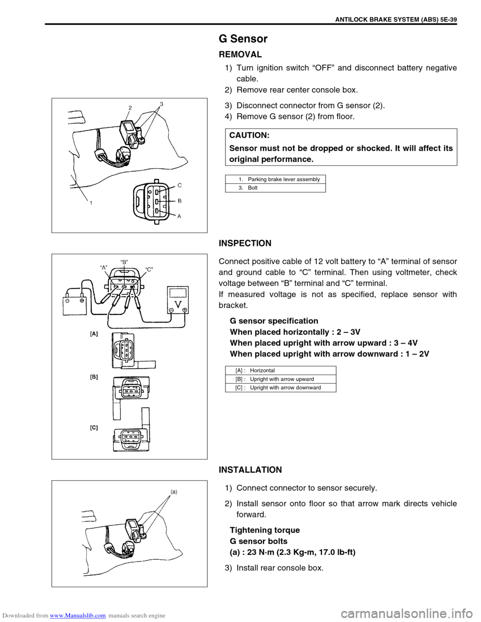
3) Disconnect connector from G sensor (2).
4) Remove G sensor (2) from floor.
INSPECTION
Connect positive cable of 12 volt battery to “A” terminal of sensor
and ground cable to “C” terminal. Then using voltmeter, check
voltage between “B” terminal and “C” terminal.
If measured voltage is not as specified, replace sensor with
bracket.
G sensor specification
When placed horizontally : 2 – 3V
When placed upright with arrow upward : 3 – 4V
When placed upright with arrow downward : 1 – 2V
INSTALLATION
1) Connect connector to sensor securely.
2) Install sensor onto floor so that arrow mark directs vehicle
forward.
Tightening torque
G sensor bolts
(a) : 23 N·m (2.3 Kg-m, 17.0 lb-ft)
3) Install rear console box.CAUTION:
Sensor must not be dropped or shocked. It will affect its
original performance.
1. Parking brake lever assembly
3. Bolt
[A] : Horizontal
[B] : Upright with arrow upward
[C] : Upright with arrow downward
Page 361 of 687
Downloaded from www.Manualslib.com manuals search engine 6-4 ENGINE GENERAL INFORMATION AND DIAGNOSIS
Precaution on fuel system service
Work must be done with no smoking, in a well-ventilated
area and away from any open flames.
As fuel feed line (between fuel pump and fuel delivery pipe)
is still under high fuel pressure even after engine was
stopped, loosening or disconnecting fuel feed line directly
may cause dangerous spout of fuel to occur where loosened
or disconnected.
Before loosening or disconnecting fuel feed line, make sure
to release fuel pressure according to “FUEL PRESSURE
RELIEF PROCEDURE”. A small amount of fuel may be
released after the fuel line is disconnected. In order to
reduce the chance of personal injury, cover the fitting to be
disconnected with a shop cloth. Put that cloth in an approved
container when disconnection is completed.
Never run engine with fuel pump relay disconnected when
engine and exhaust system are hot.
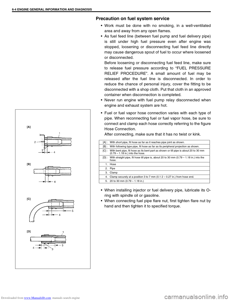
Fuel or fuel vapor hose connection varies with each type of
pipe. When reconnecting fuel or fuel vapor hose, be sure to
connect and clamp each hose correctly referring to the figure
Hose Connection.
After connecting, make sure that it has no twist or kink.
When installing injector or fuel delivery pipe, lubricate its O-
ring with spindle oil or gasoline.
When connecting fuel pipe flare nut, first tighten flare nut by
hand and then tighten it to specified torque.
[A] : With short pipe, fit hose as far as it reaches pipe joint as shown.
[B] : With following type pipe, fit hose as far as its peripheral projection as shown.
[C] : With bent pipe, fit hose as its bent part as shown or till pipe is about 20 to 30 mm
(0.79 – 1.18 in.) into the hose.
[D] : With straight pipe, fit hose till pipe is, about 20 to 30 mm (0.79 – 1.18 in.) into the
hose.
1. Hose
2. Pipe
3. Clamp
4. Clamp securely at a position 3 to 7 mm (0.1 2 – 0.27 in.) from hose end.
5. 20 to 30 mm (0.79 – 1.18 in.)
Page 363 of 687
Downloaded from www.Manualslib.com manuals search engine 6-6 ENGINE GENERAL INFORMATION AND DIAGNOSIS
Engine Diagnosis
General Description
This vehicle is equipped with an engine and emission control system which are under control of ECM.
The engine and emission control system in this vehicle are controlled by ECM. ECM has an On-Board Diagnos-
tic system which detects a malfunction in this system and abnormality of those parts that influence the engine
exhaust emission. When diagnosing engine troubles, be sure to have full understanding of the outline of “On-
Board Diagnostic System” and each item in “Precaution in Diagnosing Trouble” and execute diagnosis accord-
ing to “ENGINE DIAGNOSTIC FLOW TABLE”.
There is a close relationship between the engine mechanical, engine cooling system, ignition system, exhaust
system, etc. and the engine and emission control system in their structure and operation. In case of an engine
trouble, even when the malfunction indicator lamp (MIL) doesn’t turn ON, it should be diagnosed according to
this flow table.
On-Board Diagnostic System (Vehicle with
Immobilizer Indicator Lamp)
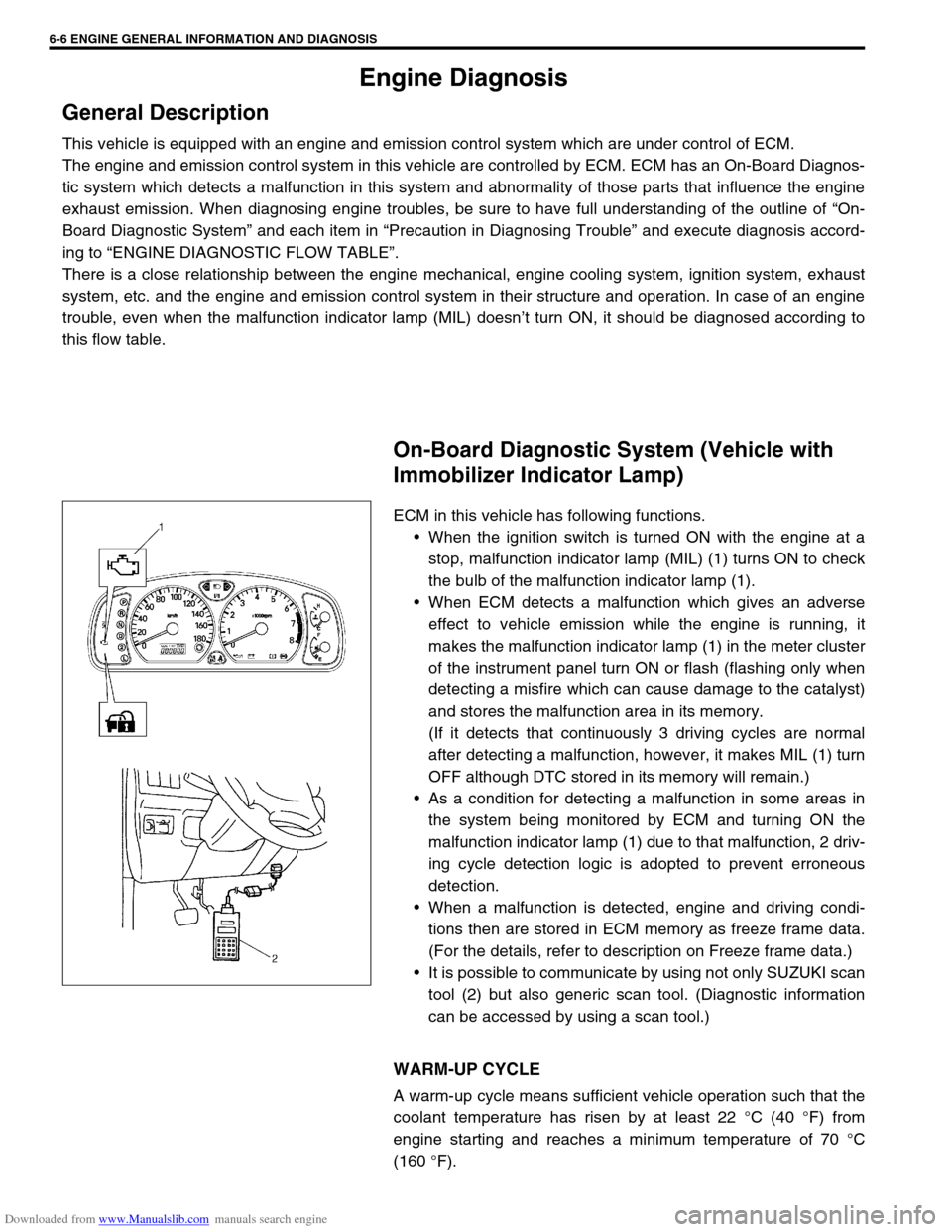
ECM in this vehicle has following functions.
When the ignition switch is turned ON with the engine at a
stop, malfunction indicator lamp (MIL) (1) turns ON to check
the bulb of the malfunction indicator lamp (1).
When ECM detects a malfunction which gives an adverse
effect to vehicle emission while the engine is running, it
makes the malfunction indicator lamp (1) in the meter cluster
of the instrument panel turn ON or flash (flashing only when
detecting a misfire which can cause damage to the catalyst)
and stores the malfunction area in its memory.
(If it detects that continuously 3 driving cycles are normal
after detecting a malfunction, however, it makes MIL (1) turn
OFF although DTC stored in its memory will remain.)
As a condition for detecting a malfunction in some areas in
the system being monitored by ECM and turning ON the
malfunction indicator lamp (1) due to that malfunction, 2 driv-
ing cycle detection logic is adopted to prevent erroneous
detection.
When a malfunction is detected, engine and driving condi-
tions then are stored in ECM memory as freeze frame data.
(For the details, refer to description on Freeze frame data.)
It is possible to communicate by using not only SUZUKI scan
tool (2) but also generic scan tool. (Diagnostic information
can be accessed by using a scan tool.)
WARM-UP CYCLE
A warm-up cycle means sufficient vehicle operation such that the
coolant temperature has risen by at least 22 °C (40 °F) from
engine starting and reaches a minimum temperature of 70 °C
(160 °F).
Page 375 of 687

Downloaded from www.Manualslib.com manuals search engine 6-18 ENGINE GENERAL INFORMATION AND DIAGNOSIS
DTC NO. DETECTING ITEM DETECTING CONDITION
(DTC will set when detecting :)MIL
P0702 Transmission Control System Electrical
Refer to Section 7B.
These DTCs can not be read on vehicle without
Immobilizer indicator lamp (by ECM application of
SUZUKI scan tool). P0705 Temperature Sensor Circuit Malfunction
P0710Transmission Temperature Sensor Circuit Mal-
function
P0715Input / Turbine Speed Sensor Circuit Malfunc-
tion
P0720Output Shaft Speed Sensor Circuit Malfunc-
tion
P0725 Engine Speed Input Circuit Malfunction
P0730 Incorrect Gear Ratio
P0743 Torque Converter Clutch Circuit Electrical
P0753 Shift Solenoid A Electrical
P0758 Shift Solenoid B Electrical
P0763 Shift Solenoid C Electrical
P0768 Shift Solenoid D Electrical
P1700 Throttle Position Signal Input Malfunction
P1702Internal Control Module Memory Check Some
Error
P1709Engine Coolant Temperature Signal Input
Malfunction
P1887 Transfer Signal
P1620
(No.84)ECU code not registered
Refer to Section 8G. P1621
(No.83)No ECU code transmitted from Immobilizer
Control Module
P1622
(No.82)Faulty in ECM
P1623
(No.81)ECU code not matched
NOTE:
For ( ) marked No. in DTC column, it is used for vehicle without Immobilizer indicator lamp.
DTC No.12 appears when none of the other codes is identified (vehicle without Immobilizer indica-
tor lamp).