Electric SUZUKI JIMNY 2005 3.G Service Owner's Manual
[x] Cancel search | Manufacturer: SUZUKI, Model Year: 2005, Model line: JIMNY, Model: SUZUKI JIMNY 2005 3.GPages: 687, PDF Size: 13.38 MB
Page 385 of 687

Downloaded from www.Manualslib.com manuals search engine 6-28 ENGINE GENERAL INFORMATION AND DIAGNOSIS
Scan Tool Data
As the data values given below are standard values estimated on the basis of values obtained from the normally
operating vehicles by using a scan tool, use them as reference values. Even when the vehicle is in good condi-
tion, there may be cases where the checked value does not fall within each specified data range. Therefore,
judgment as abnormal should not be made by checking with these data alone.
Also, conditions in the below table that can be checked by the scan tool are those detected by ECM and output
from ECM as commands and there may be cases where the engine or actuator is not operating (in the condi-
tion) as indicated by the scan tool. Be sure to use the timing light to check the ignition timing.
NOTE:
With the generic scan tool, only star (
✱
✱✱ ✱) marked data in the table below can be read.
The triangle (
∆
∆∆ ∆) marked data in the table below can not be read for vehicle without immobilizer indi-
cator lamp at combination meter.
When checking the data with the engine running at idle or racing, be sure to shift M/T gear to the
neutral gear position and A/T gear to the “Park” position and pull the parking brake fully. Also, if
nothing or “no load” is indicated, turn OFF A/C, all electric loads, P/S and all the other necessary
switches.
SCAN TOOL DATA CONDITION REFERENCE VALUES
✱
✱✱ ✱FUEL SYSTEM B1 (FUEL
SYSTEM STATUS)At specified idle speed after warming up CLOSED (closed loop)
✱
✱✱ ✱
CALC LOAD
(CALCULATED LOAD
VALUE)At specified idle speed with no load after
warming up3 – 9 %
At 2500 r/min with no load after warming up 12 – 17 %
✱
✱✱ ✱COOLANT TEMP.
(ENGINE COOLANT
TEMP.)At specified idle speed after warming up 80 – 100 °C, 176 – 212 °F
✱
✱✱ ✱SHORT FT B1 (SHORT
TERM FUEL TRIM)At specified idle speed after warming up– 20 – +20 %
✱
✱✱ ✱LONG FT B1 (LONG TERM
FUEL TRIM)At specified idle speed after warming up– 15 – +15 %
✱
✱✱ ✱MAP (INTAKE MANIFOLD
ABSOLUTE PRESSURE)At specified idle speed with no load after30 – 37 kPa,
220 – 340 mmHg
✱
✱✱ ✱
ENGINE SPEED At idling with no load after warming upDesired idle speed
±50 r/min
✱
✱✱ ✱VEHICLE SPEED At stop 0 km/h, 0 MPH
✱
✱✱ ✱IGNITION ADVANCE
(IGNITION TIMING
ADVANCE FOR NO.1 CYL-
INDER)At specified idle speed with no load after
warming up5 – 16° BTDC
✱
✱✱ ✱
INTAKE AIR TEMP. At specified idle speed after warming upAmbient temp. :
+15 °C (59 °F)
–5 °C (23 °F)
✱
✱✱ ✱MAF (MASS AIR FLOW
RATE)At specified idle speed with no load after
warming up1 – 4 gm/sec
✱
✱✱ ✱
THROTTLE POS
(THROTTLE POSITION)Ignition switch
ON / engine
stoppedThrottle valve fully closed 7 – 18 %
Throttle valve fully open 70 – 90 %
✱
✱✱ ✱O2S B1 S1 (HEATED OXY-
GEN SENSOR-1)At specified idle speed after warming up 0.01 – 0.95 V
Page 386 of 687

Downloaded from www.Manualslib.com manuals search engine ENGINE GENERAL INFORMATION AND DIAGNOSIS 6-29
∆✱
✱✱ ✱O2S B1 S2 (HEATED OXY-
GEN SENSOR-2)When engine is running at 2000 r/min. for
3 min or longer after warming up.0.01 – 0.95 V
∆✱
✱✱ ✱PSP SW No load to power steering. OFF
DESIRED IDLE
(DESIRED IDLE SPEED)At idling with no load after warming up, M/T
at neutral, A/T at “P” rangeM/T 700 r/min
A/T 750 r/min
TP SENSOR VOLT
(THROTTLE POSITION
SENSOR OUTPUT VOLT-
AGE)Ignition switch
ON / engine
stoppedThrottle valve fully closed More than 0.2 V
Throttle valve fully open Less than 4.8 V
INJ PULSE WIDTH (FUEL
INJECTION PULSE
WIDTH)At specified idle speed with no load after
warming up2.0 – 3.6 msec.
At 2500 r/min with no load after warming up 2.0 – 3.6 msec.
IAC FLOW DUTY (IDLE
AIR CONTROL FLOW
DUTY)At idling with no load after warming up 5 – 25 %
TOTAL FT B1 At specified idle speed after warming up– 35 – +35 %
BATTERY VOLTAGE Ignition switch ON / engine stop 12 – 15 V
CANIST PRG DUTY
(EVAP CANISTER PURGE
FLOW DUTY)–0 – 100 %
CLOSED THROT POS
(CLOSED THROTTLE
POSITION)Throttle valve at idle position ON
Throttle valve opens larger than idle posi-
tionOFF
FUEL CUTWhen engine is at fuel cut condition ON
Other than fuel cut condition OFF
A/C CONDENSER FANIgnition switch
ONA/C not operating OFF
A/C operating ON
ELECTRIC LOADIgnition switch ON / Headlight, small light,
heater fan and rear window defogger all
turned OFFOFF
Ignition switch ON / Headlight, small light,
heater fan or rear window defogger turned
ONON
A/C SWITCHEngine running after warming up, A/C not
operatingOFF
Engine running after warming up, A/C oper-
atingON
PNP SIGNAL (PARK / NEU-
TRAL POSITION SIGNAL)
A/T onlyIgnition switch
ONSelector lever in “P” or “N”
positionP/N Range
Selector lever in “R”, “D”,
“2” or “L” positionD Range
EGR VALVE At specified idle speed after warming up 0 %
∆FUEL TANK LEVEL–0 – 100 %
BAROMETRIC PRESS–Display the barometric pres-
sure
FUEL PUMPWithin 3 seconds after ignition switch ON or
engine runningON
Engine stop at ignition switch ON. OFF SCAN TOOL DATA CONDITION REFERENCE VALUES
Page 388 of 687

Downloaded from www.Manualslib.com manuals search engine ENGINE GENERAL INFORMATION AND DIAGNOSIS 6-31
THROTTLE POS (ABSOLUTE THROTTLE POSITION, %)
When throttle position sensor is fully closed position, throttle opening is indicated as 0% and 100% full open
position.
OXYGEN SENSOR B1 S1 (HEATED OXYGEN SENSOR-1, V)
It indicates output voltage of HO2S-1 installed on exhaust manifold (pre-catalyst).
OXYGEN SENSOR B1 S2 (HEATED OXYGEN SENSOR-2, V)
It indicates output voltage of HO2S-2 installed on exhaust pipe (post-catalyst). It is used to detect catalyst dete-
rioration.
DESIRED IDLE (DESIRED IDLE SPEED, rpm)
The Desired Idle Speed is an ECM internal parameter which indicates the ECM requested idle. If the engine is
not running, this number is not valid.
TP SENSOR VOLT (THROTTLE POSITION SENSOR OUTPUT VOLTAGE, V)
The Throttle Position Sensor reading provides throttle valve opening information in the form of voltage.
INJ PULSE WIDTH (FUEL INJECTION PULSE WIDTH, msec.)
This parameter indicates time of the injector drive (valve opening) pulse which is output from ECM (but injector
drive time of NO.1 cylinder for multiport fuel injection).
IAC FLOW DUTY (IDLE AIR (SPEED) CONTROL DUTY, %)
This parameter indicates current flow time rate within a certain set cycle of IAC valve (valve opening rate) which
controls the amount of bypass air (idle speed).
TOTAL FUEL TRIM (%)
The value of Total Fuel Trim is obtained by putting values of short Term Fuel Trim and Long Term Fuel Trim
together. This value indicates how much correction is necessary to keep the air / fuel mixture stoichiometrical.
BATTERY VOLTAGE (V)
This parameter indicates battery positive voltage inputted from main relay to ECM.
CANIST PURGE DUTY (EVAP CANISTER PURGE FLOW DUTY, %)
This parameter indicates valve ON (valve open) time rate within a certain set cycle of EVAP purge solenoid
valve which controls the amount of EVAP purge.
0% means that the purge valve is completely closed while 100% is a fully open valve.
CLOSED THROTTLE POSITION (ON / OFF)
This parameter will read ON when throttle valve is fully closed, or OFF when the throttle is not fully closed.
FUEL CUT (ON / OFF)
ON : Fuel being cut (output signal to injector is stopped)
OFF : Fuel not being cut
A/C CONDENSER FAN (A/C CONDENSER FAN RELAY, ON / OFF)
ON : Command for condenser fan relay operation being output.
OFF : Command for relay operation not being output.
ELECTRIC LOAD (ON / OFF)
ON : Headlight, small light, heater fan or rear window defogger ON signal inputted.
OFF : Above electric loads all turned OFF.
A/C SWITCH (ON / OFF)
ON : Command for A/C operation being output from ECM to A/C amplifier.
OFF : Command for A/C operation not being output.
Page 476 of 687
Downloaded from www.Manualslib.com manuals search engine ENGINE GENERAL INFORMATION AND DIAGNOSIS 6-119
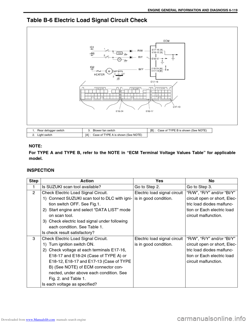
Table B-6 Electric Load Signal Circuit Check
INSPECTION
1. Rear defogger switch 3. Blower fan switch [B] : Case of TYPE B is shown (See NOTE)
2. Light switch [A] : Case of TYPE A is shown (See NOTE)
NOTE:
For TYPE A and TYPE B, refer to the NOTE in “ECM Terminal Voltage Values Table” for applicable
model.
Step Action Yes No
1 Is SUZUKI scan tool available? Go to Step 2. Go to Step 3.
2 Check Electric Load Signal Circuit.
1) Connect SUZUKI scan tool to DLC with igni-
tion switch OFF. See Fig.1.
2) Start engine and select “DATA LIST” mode
on scan tool.
3) Check electric load signal under following
each condition. See Table 1.
Is check result satisfactory?Electric load signal circuit
is in good condition.“R/W”, “R/Y” and/or “Bl/Y”
circuit open or short, Elec-
tric load diodes malfunc-
tion or Each electric load
circuit malfunction.
3 Check Electric Load Signal Circuit.
1) Turn ignition switch ON.
2) Check voltage at each terminals E17-16,
E18-17 and E18-24 (Case of TYPE A) or
E18-12, E18-17 and E17-13 (Case of TYPE
B) (See NOTE) of ECM connector con-
nected, under above each condition. See
Fig. 2. and Table 1.
Is each voltage as specified?Electric load signal circuit
is in good condition.“R/W”, “R/Y” and/or “Bl/Y”
circuit open or short, Elec-
tric load diodes malfunc-
tion or Each electric load
circuit malfunction.
Page 487 of 687
Downloaded from www.Manualslib.com manuals search engine 6A1-6 ENGINE MECHANICAL (M13 ENGINE)
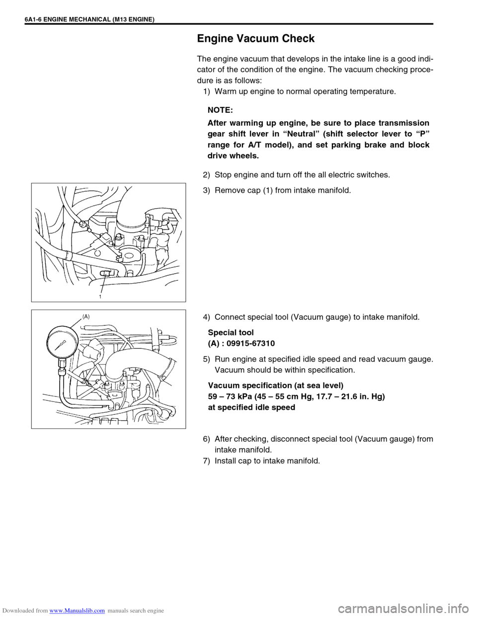
Engine Vacuum Check
The engine vacuum that develops in the intake line is a good indi-
cator of the condition of the engine. The vacuum checking proce-
dure is as follows:
1) Warm up engine to normal operating temperature.
2) Stop engine and turn off the all electric switches.
3) Remove cap (1) from intake manifold.
4) Connect special tool (Vacuum gauge) to intake manifold.
Special tool
(A) : 09915-67310
5) Run engine at specified idle speed and read vacuum gauge.
Vacuum should be within specification.
Vacuum specification (at sea level)
59 – 73 kPa (45 – 55 cm Hg, 17.7 – 21.6 in. Hg)
at specified idle speed
6) After checking, disconnect special tool (Vacuum gauge) from
intake manifold.
7) Install cap to intake manifold.NOTE:
After warming up engine, be sure to place transmission
gear shift lever in “Neutral” (shift selector lever to “P”
range for A/T model), and set parking brake and block
drive wheels.
Page 500 of 687
Downloaded from www.Manualslib.com manuals search engine ENGINE MECHANICAL (M13 ENGINE) 6A1-19
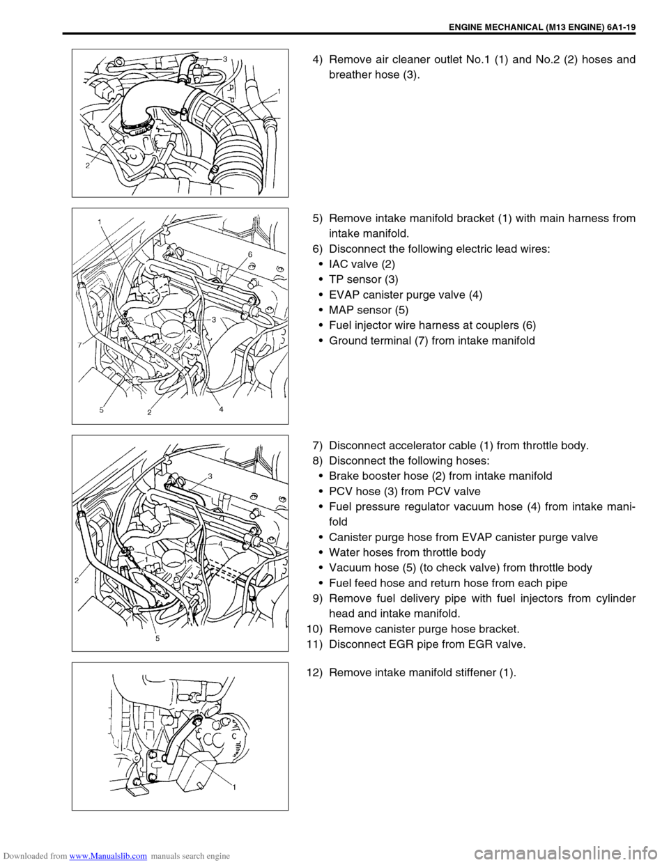
4) Remove air cleaner outlet No.1 (1) and No.2 (2) hoses and
breather hose (3).
5) Remove intake manifold bracket (1) with main harness from
intake manifold.
6) Disconnect the following electric lead wires:
IAC valve (2)
TP sensor (3)
EVAP canister purge valve (4)
MAP sensor (5)
Fuel injector wire harness at couplers (6)
Ground terminal (7) from intake manifold
7) Disconnect accelerator cable (1) from throttle body.
8) Disconnect the following hoses:
Brake booster hose (2) from intake manifold
PCV hose (3) from PCV valve
Fuel pressure regulator vacuum hose (4) from intake mani-
fold
Canister purge hose from EVAP canister purge valve
Water hoses from throttle body
Vacuum hose (5) (to check valve) from throttle body
Fuel feed hose and return hose from each pipe
9) Remove fuel delivery pipe with fuel injectors from cylinder
head and intake manifold.
10) Remove canister purge hose bracket.
11) Disconnect EGR pipe from EGR valve.
12) Remove intake manifold stiffener (1).
Page 530 of 687
Downloaded from www.Manualslib.com manuals search engine ENGINE MECHANICAL (M13 ENGINE) 6A1-49
REMOVAL
1) Relieve fuel pressure referring to “Fuel Pressure Relief Pro-
cedure” in Section 6.
2) Disconnect negative cable at battery.
3) Drain engine oil.
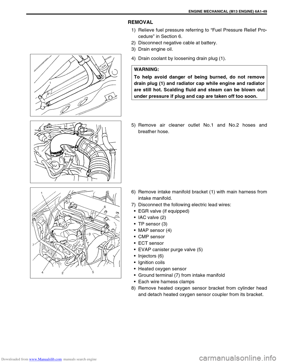
4) Drain coolant by loosening drain plug (1).
5) Remove air cleaner outlet No.1 and No.2 hoses and
breather hose.
6) Remove intake manifold bracket (1) with main harness from
intake manifold.
7) Disconnect the following electric lead wires:
EGR valve (if equipped)
IAC valve (2)
TP sensor (3)
MAP sensor (4)
CMP sensor
ECT sensor
EVAP canister purge valve (5)
Injectors (6)
Ignition coils
Heated oxygen sensor
Ground terminal (7) from intake manifold
Each wire harness clamps
8) Remove heated oxygen sensor bracket from cylinder head
and detach heated oxygen sensor coupler from its bracket. WARNING:
To help avoid danger of being burned, do not remove
drain plug (1) and radiator cap while engine and radiator
are still hot. Scalding fluid and steam can be blown out
under pressure if plug and cap are taken off too soon.
Page 542 of 687

Downloaded from www.Manualslib.com manuals search engine ENGINE MECHANICAL (M13 ENGINE) 6A1-61
6) Install exhaust manifold stiffener and exhaust pipe referring
to “Exhaust Manifold” in this section.
7) Install camshafts, timing chain and chain cover referring to
“Camshaft, Tappet and Shim”, “Timing Chain and Chain
Tensioner” and “Timing Chain Cover” in this section.
8) Install cylinder head cover and oil pan referring to “Cylinder
Head Cover” and “Oil Pan and Oil Pump Strainer” in this sec-
tion.
9) Install intake manifold stiffener and connect each hoses and
electric lead wires securely.
10) Install air cleaner outlet hoses.
11) Install radiator with cooling fan and connect A/T fluid hoses
(vehicle with A/T), radiator inlet and outlet hoses referring to
“Water Pump Belt and Cooling Fan” and “Radiator” in Sec-
tion 6B.
12) Adjust generator belt tension referring to “Water Pump Belt
Tension” in Section 6B.
13) Adjust A/C compressor and/or P/S pump belt tension (if
equipped) referring to “Compressor Drive Belt” in Section 1B
or “Power Steering Belt” in Section 3B1.
14) Adjust accelerator cable play referring to “Accelerator Cable
Adjustment” in Section 6E.
15) Check to ensure that all removed parts are back in place.
Reinstall any necessary parts which have not been rein-
stalled.
16) Refill cooling system with coolant, engine with engine oil and
A/T with specified A/T fluid (vehicle with A/T).
17) Connect negative cable at battery.
18) Verify that there is no fuel leakage, coolant leakage, oil leak-
age, A/T fluid leakage (vehicle with A/T) and exhaust gas
leakage at each connection.
Page 555 of 687
Downloaded from www.Manualslib.com manuals search engine 6A1-74 ENGINE MECHANICAL (M13 ENGINE)
a) For right hand steering vehicle:
With hose connected, detach A/C compressor from its
bracket.
b) For left hand steering vehicle:
i) Recover refrigerant from refrigeration system using recov-
ery and recycling equipment.
ii) Disconnect magnet clutch lead wire.
iii) Remove suction pipe and disconnect discharge pipe from
A/C compressor.
iv) Remove A/C compressor from its bracket.
When servicing above steps, refer to “Compressor” in Section 1B.
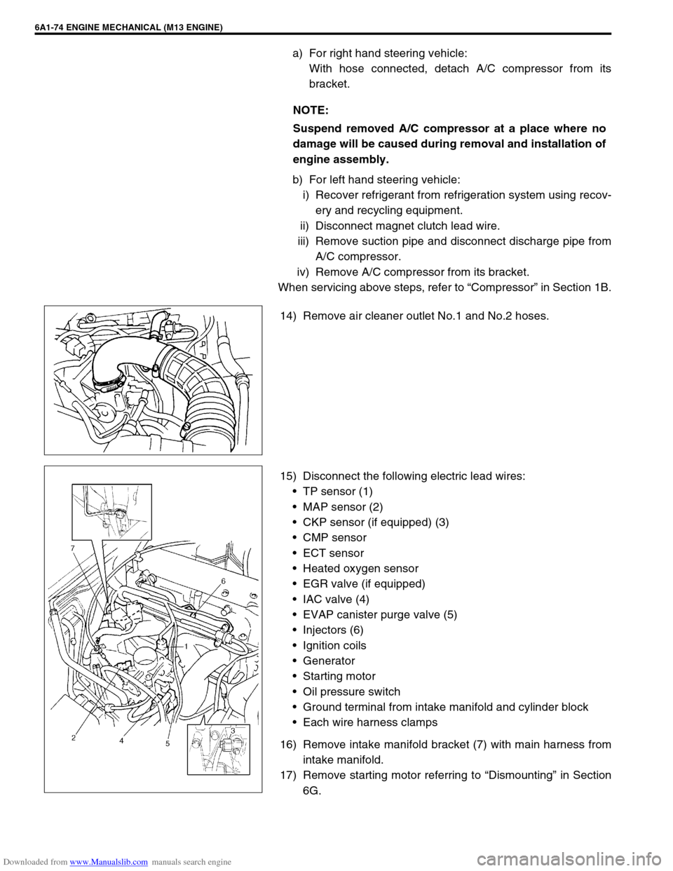
14) Remove air cleaner outlet No.1 and No.2 hoses.
15) Disconnect the following electric lead wires:
TP sensor (1)
MAP sensor (2)
CKP sensor (if equipped) (3)
CMP sensor
ECT sensor
Heated oxygen sensor
EGR valve (if equipped)
IAC valve (4)
EVAP canister purge valve (5)
Injectors (6)
Ignition coils
Generator
Starting motor
Oil pressure switch
Ground terminal from intake manifold and cylinder block
Each wire harness clamps
16) Remove intake manifold bracket (7) with main harness from
intake manifold.
17) Remove starting motor referring to “Dismounting” in Section
6G. NOTE:
Suspend removed A/C compressor at a place where no
damage will be caused during removal and installation of
engine assembly.
Page 557 of 687
Downloaded from www.Manualslib.com manuals search engine 6A1-76 ENGINE MECHANICAL (M13 ENGINE)
26) Remove bolts and nuts fastening cylinder block and trans-
mission.
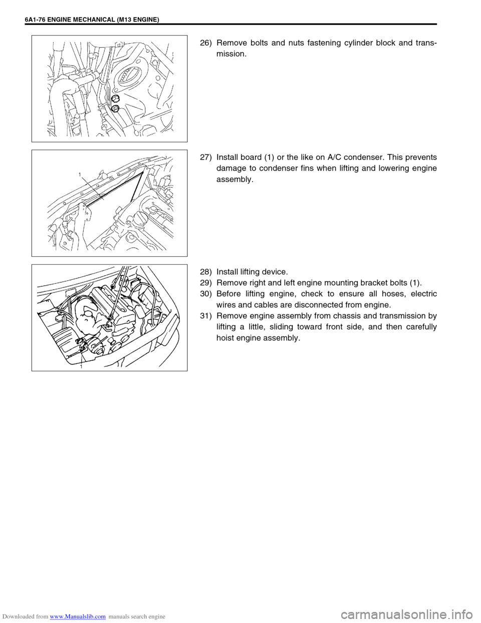
27) Install board (1) or the like on A/C condenser. This prevents
damage to condenser fins when lifting and lowering engine
assembly.
28) Install lifting device.
29) Remove right and left engine mounting bracket bolts (1).
30) Before lifting engine, check to ensure all hoses, electric
wires and cables are disconnected from engine.
31) Remove engine assembly from chassis and transmission by
lifting a little, sliding toward front side, and then carefully
hoist engine assembly.