Manual Transmission SUZUKI JIMNY 2005 3.G Service Owner's Manual
[x] Cancel search | Manufacturer: SUZUKI, Model Year: 2005, Model line: JIMNY, Model: SUZUKI JIMNY 2005 3.GPages: 687, PDF Size: 13.38 MB
Page 378 of 687

Downloaded from www.Manualslib.com manuals search engine ENGINE GENERAL INFORMATION AND DIAGNOSIS 6-21
Engine basic inspection
This check is very important for troubleshooting when ECM has detected no DTC and no abnormality has been
found in visual inspection.
Follow the flow table carefully.
Step Action Yes No
1Was “Engine Diag. Flow Table” performed? Go to Step 2. Go to “Engine Diag. Flow
Table”.
2 Check battery voltage.
Is it 11 V or more?Go to Step 3. Charge or replace battery.
3 Is engine cranked? Go to Step 4. Go to “Diagnosis” in Sec-
tion 6G.
4 Does engine start? Go to Step 5. Go to Step 9.
5 Check idle speed as follows :
1) Warm up engine to normal operating temp.
2) Shift transmission to neutral position for M/T
(“P” position for A/T).
3) All of electrical loads are switched off.
4) Check engine idle speed with scan tool.
See Fig. 1.
Is it 650 – 750 r/min (700 – 800 r/min. for A/T
vehicle)?Go to Step 6. Go to “Engine Diagnosis
Table”.
6 Is SUZUKI scan tool available? Go to Step 8. Go to Step 7.
7 Check ignition timing as follows :
1) Connect test switch terminal (2) of monitor
coupler (1) to ground. See Fig. 2.
2) Remove air cleaner bolt and crips and shift
air cleaner position to observe ignition tim-
ing.
3) Using timing light (1), check initial ignition
timing.
See Fig. 4.
Is it 5° ± 3° BTDC at specified idle speed?Go to “Engine Diagnosis
Table”.Check ignition control
related parts referring to
Section 6F.
8 Check ignition timing as follows :
1) Select “MISC” mode on SUZUKI scan tool
and fix ignition timing to initial one. See Fig.
3.
2) Remove air cleaner bolt and crips and shift
air cleaner position to observe ignition tim-
ing.
3) Using timing light (1), check initial ignition
timing. See Fig. 4.
Is it 5° ± 3° BTDC at specified idle speed?Go to “Engine Diagnosis
Table”.Check ignition control
related parts referring to
Section 6F.
9 Check immobilizer system malfunction as fol-
lows (if equipped) :
1) Check immobilizer indicator lamp or MIL
(malfunction indicator lamp) for flashing.
Is it flashing when ignition switch is turned to
ON position?Go to “Diagnosis” in Sec-
tion 8G.Go to Step 10.
Page 399 of 687
Downloaded from www.Manualslib.com manuals search engine 6-42 ENGINE GENERAL INFORMATION AND DIAGNOSIS
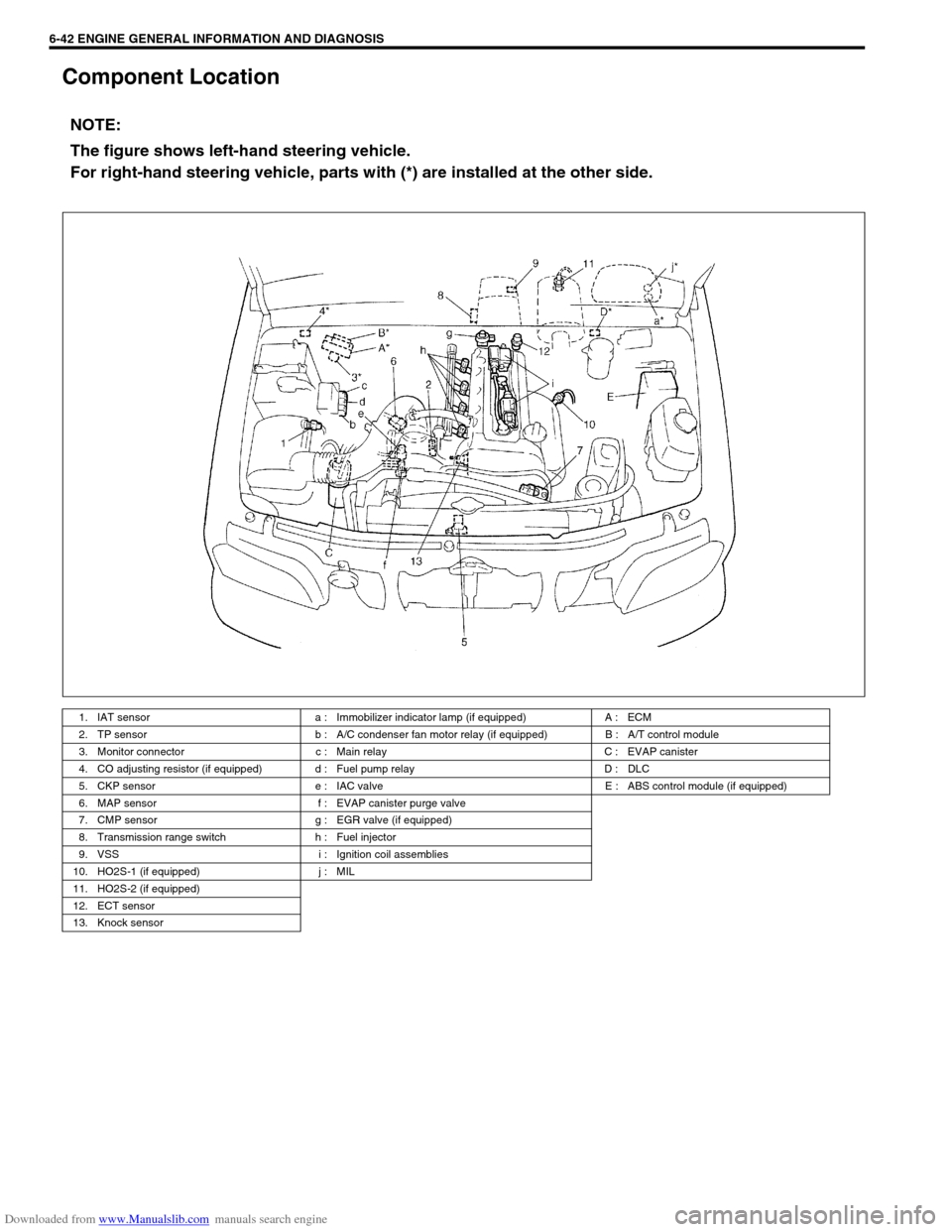
Component Location
NOTE:
The figure shows left-hand steering vehicle.
For right-hand steering vehicle, parts with (*) are installed at the other side.
1. IAT sensor a : Immobilizer indicator lamp (if equipped) A : ECM
2. TP sensor b : A/C condenser fan motor relay (if equipped) B : A/T control module
3. Monitor connector c : Main relay C : EVAP canister
4. CO adjusting resistor (if equipped) d : Fuel pump relay D : DLC
5. CKP sensor e : IAC valve E : ABS control module (if equipped)
6. MAP sensor f : EVAP canister purge valve
7. CMP sensor g : EGR valve (if equipped)
8. Transmission range switch h : Fuel injector
9. VSS i : Ignition coil assemblies
10. HO2S-1 (if equipped) j : MIL
11. HO2S-2 (if equipped)
12. ECT sensor
13. Knock sensor
Page 458 of 687
Downloaded from www.Manualslib.com manuals search engine ENGINE GENERAL INFORMATION AND DIAGNOSIS 6-101
DTC P1500 Engine Starter Signal Circuit Malfunction
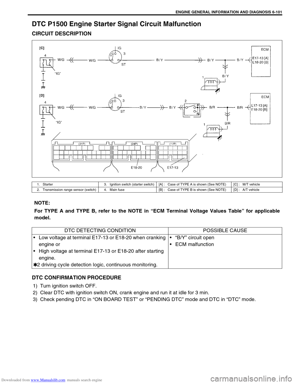
CIRCUIT DESCRIPTION
DTC CONFIRMATION PROCEDURE
1) Turn ignition switch OFF.
2) Clear DTC with ignition switch ON, crank engine and run it at idle for 3 min.
3) Check pending DTC in “ON BOARD TEST” or “PENDING DTC” mode and DTC in “DTC” mode.
1. Starter 3. Ignition switch (starter switch) [A] : Case of TYPE A is shown (See NOTE) [C] : M/T vehicle
2. Transmission range sensor (switch) 4. Main fuse [B] : Case of TYPE B is shown (See NOTE) [D] : A/T vehicle
NOTE:
For TYPE A and TYPE B, refer to the NOTE in “ECM Terminal Voltage Values Table” for applicable
model.
DTC DETECTING CONDITION POSSIBLE CAUSE
Low voltage at terminal E17-13 or E18-20 when cranking
engine or
High voltage at terminal E17-13 or E18-20 after starting
engine.
✱
✱✱ ✱2 driving cycle detection logic, continuous monitoring.“B/Y” circuit open
ECM malfunction
Page 464 of 687
Downloaded from www.Manualslib.com manuals search engine ENGINE GENERAL INFORMATION AND DIAGNOSIS 6-107
DTC P1717 A/T Drive Range (Park / Neutral Position) Signal Circuit Malfunc-
tion
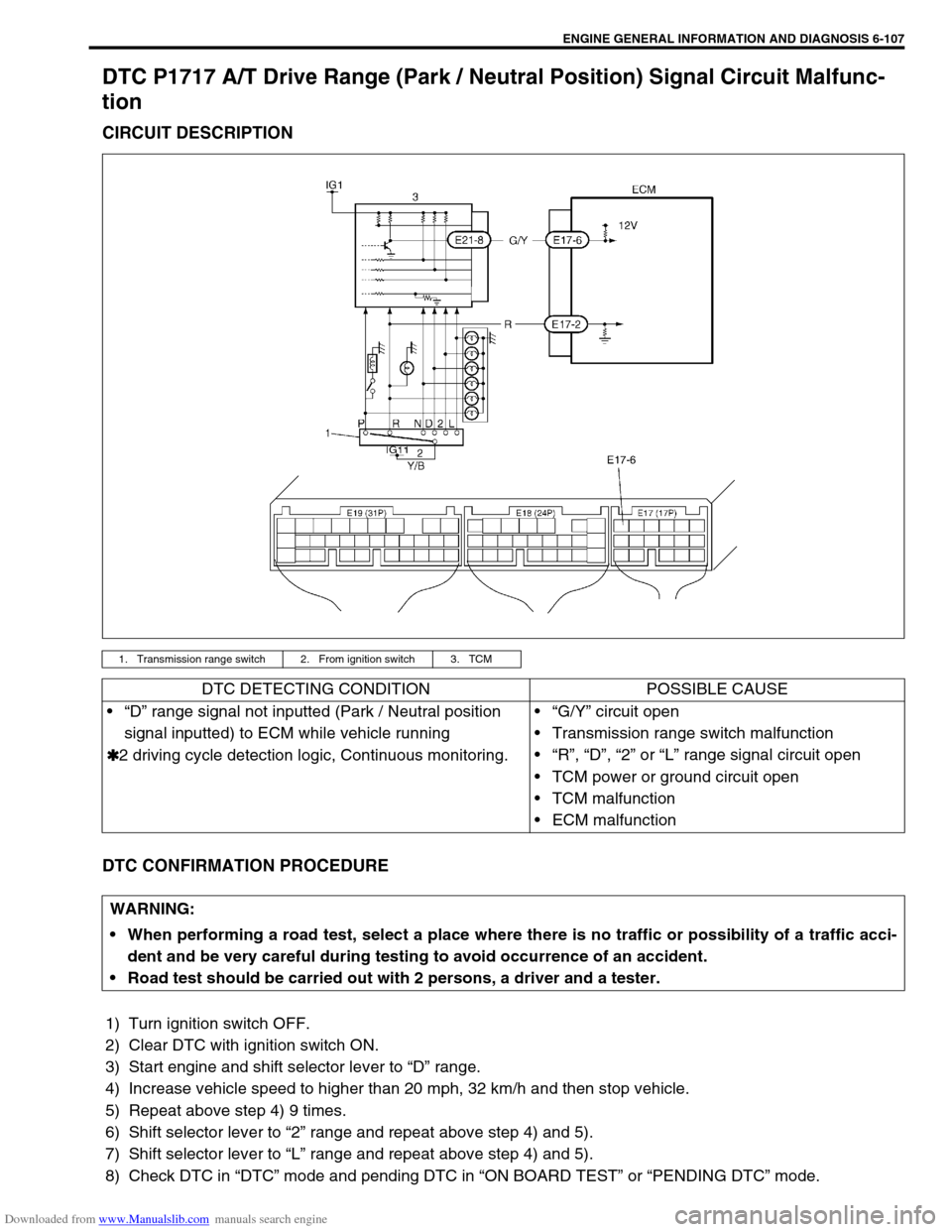
CIRCUIT DESCRIPTION
DTC CONFIRMATION PROCEDURE
1) Turn ignition switch OFF.
2) Clear DTC with ignition switch ON.
3) Start engine and shift selector lever to “D” range.
4) Increase vehicle speed to higher than 20 mph, 32 km/h and then stop vehicle.
5) Repeat above step 4) 9 times.
6) Shift selector lever to “2” range and repeat above step 4) and 5).
7) Shift selector lever to “L” range and repeat above step 4) and 5).
8) Check DTC in “DTC” mode and pending DTC in “ON BOARD TEST” or “PENDING DTC” mode.
1. Transmission range switch 2. From ignition switch 3. TCM
DTC DETECTING CONDITION POSSIBLE CAUSE
“D” range signal not inputted (Park / Neutral position
signal inputted) to ECM while vehicle running
✱
✱✱ ✱2 driving cycle detection logic, Continuous monitoring.“G/Y” circuit open
Transmission range switch malfunction
“R”, “D”, “2” or “L” range signal circuit open
TCM power or ground circuit open
TCM malfunction
ECM malfunction
WARNING:
When performing a road test, select a place where there is no traffic or possibility of a traffic acci-
dent and be very careful during testing to avoid occurrence of an accident.
Road test should be carried out with 2 persons, a driver and a tester.
Page 465 of 687
![SUZUKI JIMNY 2005 3.G Service Owners Manual Downloaded from www.Manualslib.com manuals search engine 6-108 ENGINE GENERAL INFORMATION AND DIAGNOSIS
INSPECTION
[A] Fig. 1 for Step 3 / [B] Fig. 2 for Step 4 / [C] Fig. 3 for Step 6Step Action Yes SUZUKI JIMNY 2005 3.G Service Owners Manual Downloaded from www.Manualslib.com manuals search engine 6-108 ENGINE GENERAL INFORMATION AND DIAGNOSIS
INSPECTION
[A] Fig. 1 for Step 3 / [B] Fig. 2 for Step 4 / [C] Fig. 3 for Step 6Step Action Yes](/img/20/7588/w960_7588-464.png)
Downloaded from www.Manualslib.com manuals search engine 6-108 ENGINE GENERAL INFORMATION AND DIAGNOSIS
INSPECTION
[A] Fig. 1 for Step 3 / [B] Fig. 2 for Step 4 / [C] Fig. 3 for Step 6Step Action Yes No
1Was “Engine Diag. Flow Table” performed? Go to Step 2. Go to “Engine Diag. Flow
Table”.
2 Is SUZUKI scan tool available? Go to Step 3. Go to Step 4.
3 Check PNP signal (“D” range signal).
1) Connect SUZUKI scan tool to DLC with igni-
tion switch OFF. See Fig. 1.
2) Turn ignition switch ON and check PNP sig-
nal (“P/N” or “D” range) on display when
shifting selector lever to each range.
Is “D” range on display (Is 0 – 1 V indicated) no
matter which of “R”, “D”, “2” and “L” range posi-
tions selector lever may be at? See Table 1.Intermittent trouble or
faulty ECM. Check for
intermittent referring to
“Intermittent and Poor
Connection” in Section
0A.Go to Step 5.
4 Check PNP Signal (“D” range signal).
1) Turn ignition switch ON.
2) Check voltage at terminal E17-6 of ECM
connector connected. See Fig. 2.
Is “D” range on display (Is 0 – 1 V indicated) no
matter which of “R”, “D”, “2” and “L” range posi-
tions selector lever may be at? See Table 1.Intermittent trouble or
faulty ECM. Check for
intermittent referring to
“Intermittent and Poor
Connection” in Section
0A.Go to Step 5.
5Is “P/N” range on display (Is 10 – 14 V indi-
cated) when selector lever is at one of “R”, “D”,
“2” and “L” range positions only?Check transmission range
switch and circuits refer-
ring to Section 7B.Go to Step 6.
6 Check PNP signal circuit.
1) Turn ignition switch OFF.
2) Disconnect TCM connectors.
3) Check for proper connection to TCM at ter-
minal E21-5.
4) If OK, then check voltage at terminal E21-8
in TCM connector disconnected, with igni-
tion switch ON. See Fig. 3
Is it 10 – 14 V?“Y/B” circuit open, poor
transmission range sen-
sor connector connec-
tion, select cable
maladjusted, transmis-
sion range sensor malad-
justed or transmission
range sensor malfunction.
If all above are OK, sub-
stitute a known-good TCM
and recheck.“G/Y” circuit open or poor
E17-6 connection.
If wire and connection are
OK, substitute a known-
good ECM and recheck.
Page 485 of 687
Downloaded from www.Manualslib.com manuals search engine 6A1-4 ENGINE MECHANICAL (M13 ENGINE)
Diagnosis
Diagnosis Table
Refer to “Engine Diagnosis Table” in Section 6.
Compression Check
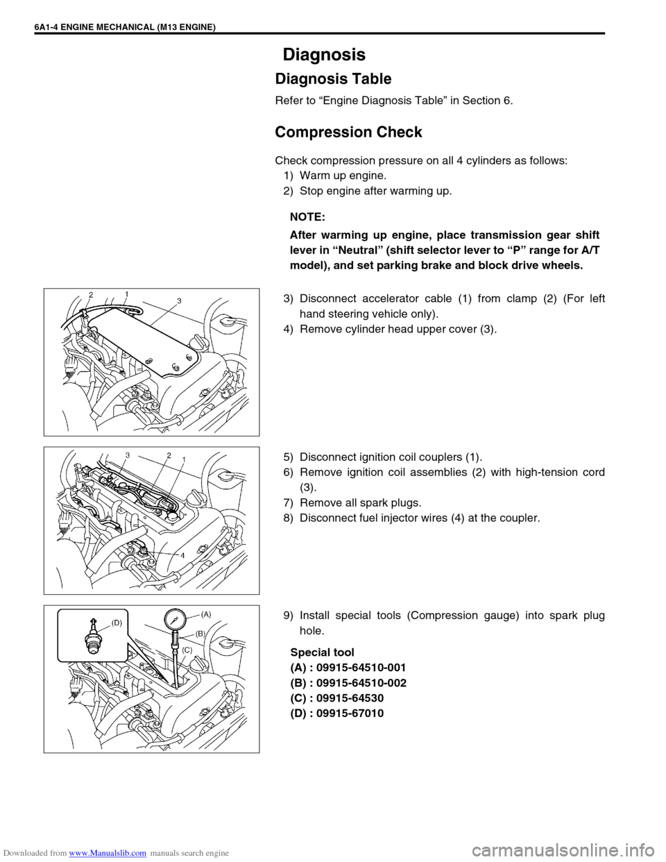
Check compression pressure on all 4 cylinders as follows:
1) Warm up engine.
2) Stop engine after warming up.
3) Disconnect accelerator cable (1) from clamp (2) (For left
hand steering vehicle only).
4) Remove cylinder head upper cover (3).
5) Disconnect ignition coil couplers (1).
6) Remove ignition coil assemblies (2) with high-tension cord
(3).
7) Remove all spark plugs.
8) Disconnect fuel injector wires (4) at the coupler.
9) Install special tools (Compression gauge) into spark plug
hole.
Special tool
(A) : 09915-64510-001
(B) : 09915-64510-002
(C) : 09915-64530
(D) : 09915-67010 NOTE:
After warming up engine, place transmission gear shift
lever in “Neutral” (shift selector lever to “P” range for A/T
model), and set parking brake and block drive wheels.
Page 487 of 687
Downloaded from www.Manualslib.com manuals search engine 6A1-6 ENGINE MECHANICAL (M13 ENGINE)
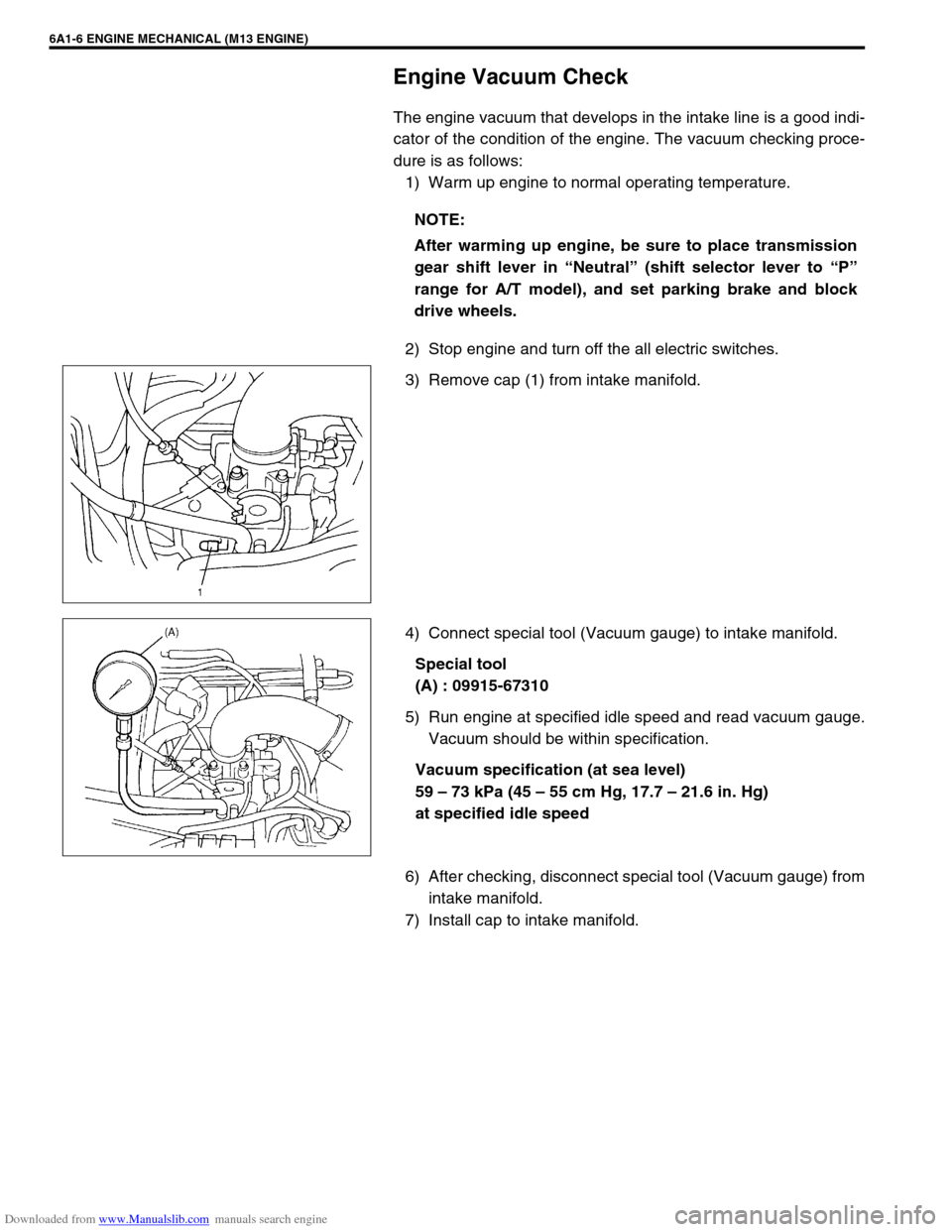
Engine Vacuum Check
The engine vacuum that develops in the intake line is a good indi-
cator of the condition of the engine. The vacuum checking proce-
dure is as follows:
1) Warm up engine to normal operating temperature.
2) Stop engine and turn off the all electric switches.
3) Remove cap (1) from intake manifold.
4) Connect special tool (Vacuum gauge) to intake manifold.
Special tool
(A) : 09915-67310
5) Run engine at specified idle speed and read vacuum gauge.
Vacuum should be within specification.
Vacuum specification (at sea level)
59 – 73 kPa (45 – 55 cm Hg, 17.7 – 21.6 in. Hg)
at specified idle speed
6) After checking, disconnect special tool (Vacuum gauge) from
intake manifold.
7) Install cap to intake manifold.NOTE:
After warming up engine, be sure to place transmission
gear shift lever in “Neutral” (shift selector lever to “P”
range for A/T model), and set parking brake and block
drive wheels.
Page 488 of 687
Downloaded from www.Manualslib.com manuals search engine ENGINE MECHANICAL (M13 ENGINE) 6A1-7
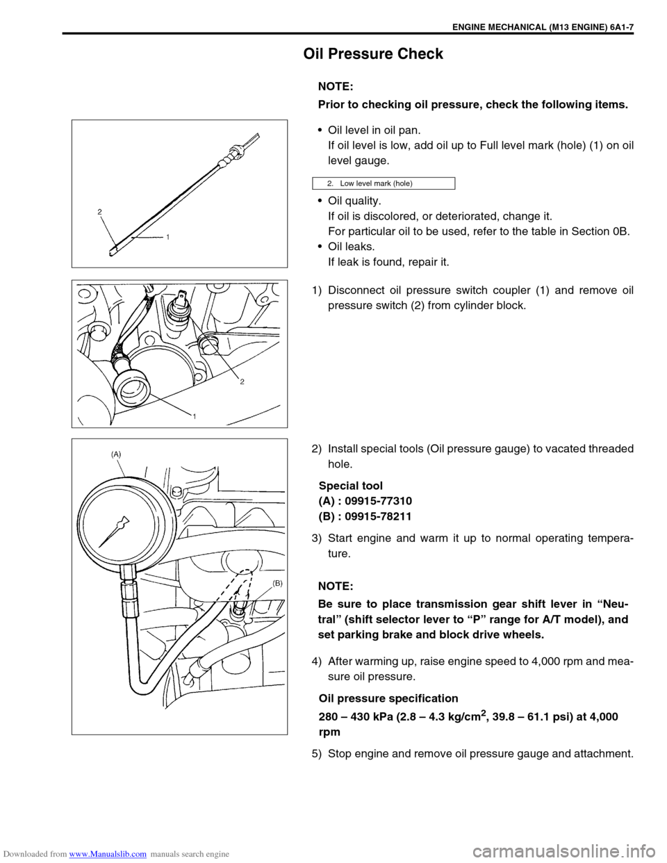
Oil Pressure Check
Oil level in oil pan.
If oil level is low, add oil up to Full level mark (hole) (1) on oil
level gauge.
Oil quality.
If oil is discolored, or deteriorated, change it.
For particular oil to be used, refer to the table in Section 0B.
Oil leaks.
If leak is found, repair it.
1) Disconnect oil pressure switch coupler (1) and remove oil
pressure switch (2) from cylinder block.
2) Install special tools (Oil pressure gauge) to vacated threaded
hole.
Special tool
(A) : 09915-77310
(B) : 09915-78211
3) Start engine and warm it up to normal operating tempera-
ture.
4) After warming up, raise engine speed to 4,000 rpm and mea-
sure oil pressure.
Oil pressure specification
280 – 430 kPa (2.8 – 4.3 kg/cm
2, 39.8 – 61.1 psi) at 4,000
rpm
5) Stop engine and remove oil pressure gauge and attachment.NOTE:
Prior to checking oil pressure, check the following items.
2. Low level mark (hole)
NOTE:
Be sure to place transmission gear shift lever in “Neu-
tral” (shift selector lever to “P” range for A/T model), and
set parking brake and block drive wheels.
Page 505 of 687
Downloaded from www.Manualslib.com manuals search engine 6A1-24 ENGINE MECHANICAL (M13 ENGINE)
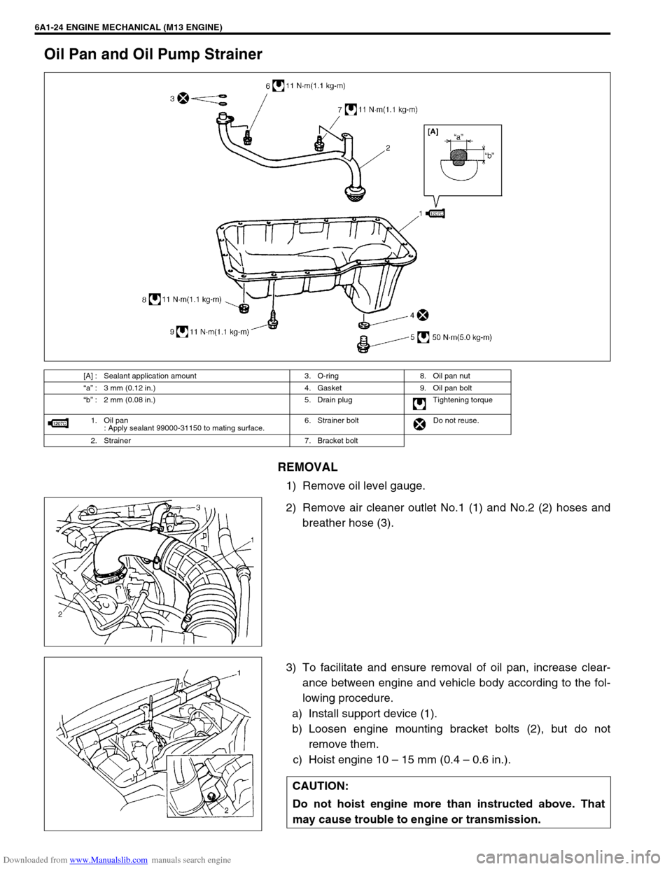
Oil Pan and Oil Pump Strainer
REMOVAL
1) Remove oil level gauge.
2) Remove air cleaner outlet No.1 (1) and No.2 (2) hoses and
breather hose (3).
3) To facilitate and ensure removal of oil pan, increase clear-
ance between engine and vehicle body according to the fol-
lowing procedure.
a) Install support device (1).
b) Loosen engine mounting bracket bolts (2), but do not
remove them.
c) Hoist engine 10 – 15 mm (0.4 – 0.6 in.).
[A] : Sealant application amount 3. O-ring 8. Oil pan nut
“a” : 3 mm (0.12 in.) 4. Gasket 9. Oil pan bolt
“b” : 2 mm (0.08 in.) 5. Drain plug Tightening torque
1. Oil pan
: Apply sealant 99000-31150 to mating surface.6. Strainer bolt Do not reuse.
2. Strainer 7. Bracket bolt
CAUTION:
Do not hoist engine more than instructed above. That
may cause trouble to engine or transmission.
Page 556 of 687
Downloaded from www.Manualslib.com manuals search engine ENGINE MECHANICAL (M13 ENGINE) 6A1-75
18) Remove heated oxygen sensor bracket from cylinder head
and detach No.1 heated oxygen sensor coupler from its
bracket.
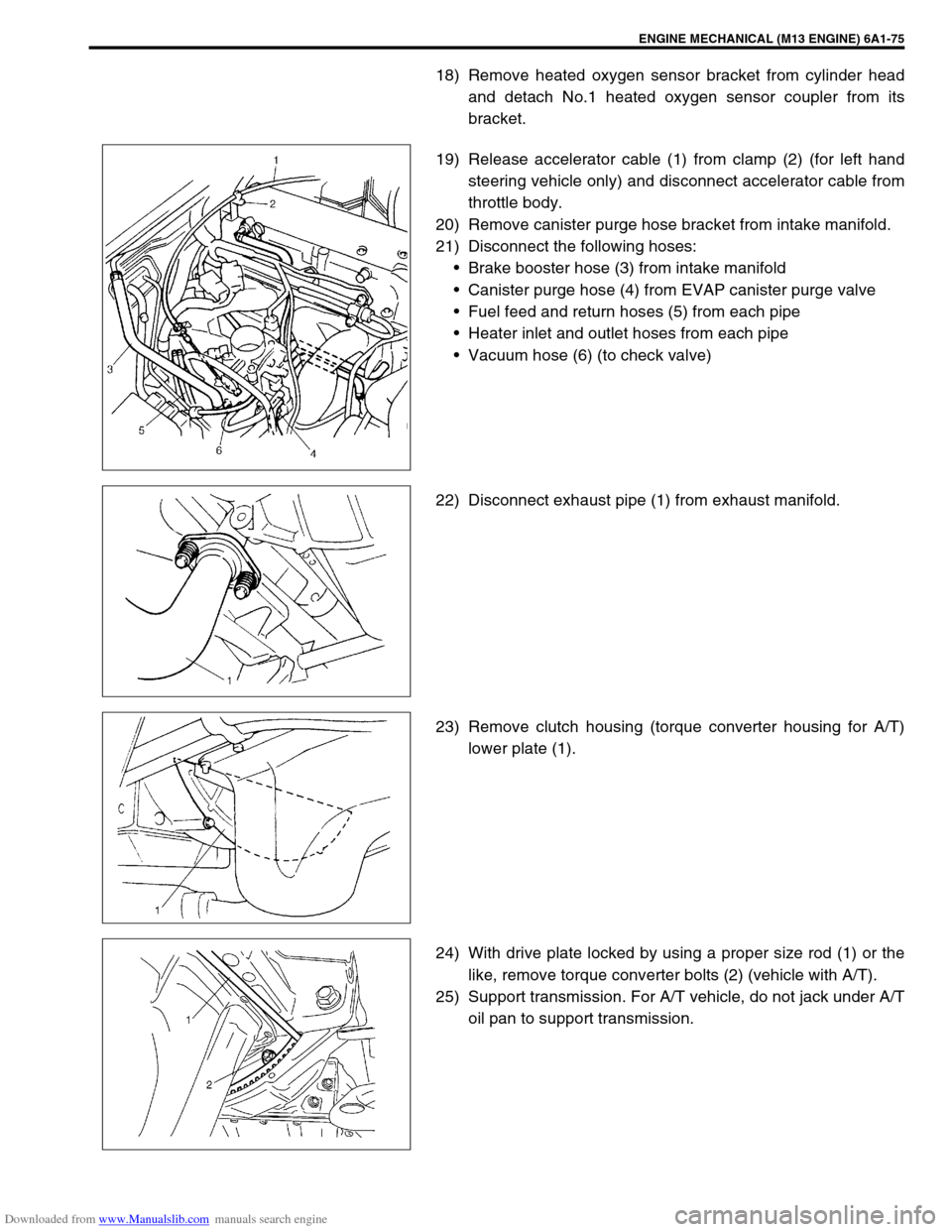
19) Release accelerator cable (1) from clamp (2) (for left hand
steering vehicle only) and disconnect accelerator cable from
throttle body.
20) Remove canister purge hose bracket from intake manifold.
21) Disconnect the following hoses:
Brake booster hose (3) from intake manifold
Canister purge hose (4) from EVAP canister purge valve
Fuel feed and return hoses (5) from each pipe
Heater inlet and outlet hoses from each pipe
Vacuum hose (6) (to check valve)
22) Disconnect exhaust pipe (1) from exhaust manifold.
23) Remove clutch housing (torque converter housing for A/T)
lower plate (1).
24) With drive plate locked by using a proper size rod (1) or the
like, remove torque converter bolts (2) (vehicle with A/T).
25) Support transmission. For A/T vehicle, do not jack under A/T
oil pan to support transmission.