brake light SUZUKI JIMNY 2005 3.G Service Owner's Manual
[x] Cancel search | Manufacturer: SUZUKI, Model Year: 2005, Model line: JIMNY, Model: SUZUKI JIMNY 2005 3.GPages: 687, PDF Size: 13.38 MB
Page 332 of 687
Downloaded from www.Manualslib.com manuals search engine ANTILOCK BRAKE SYSTEM (ABS) 5E-15
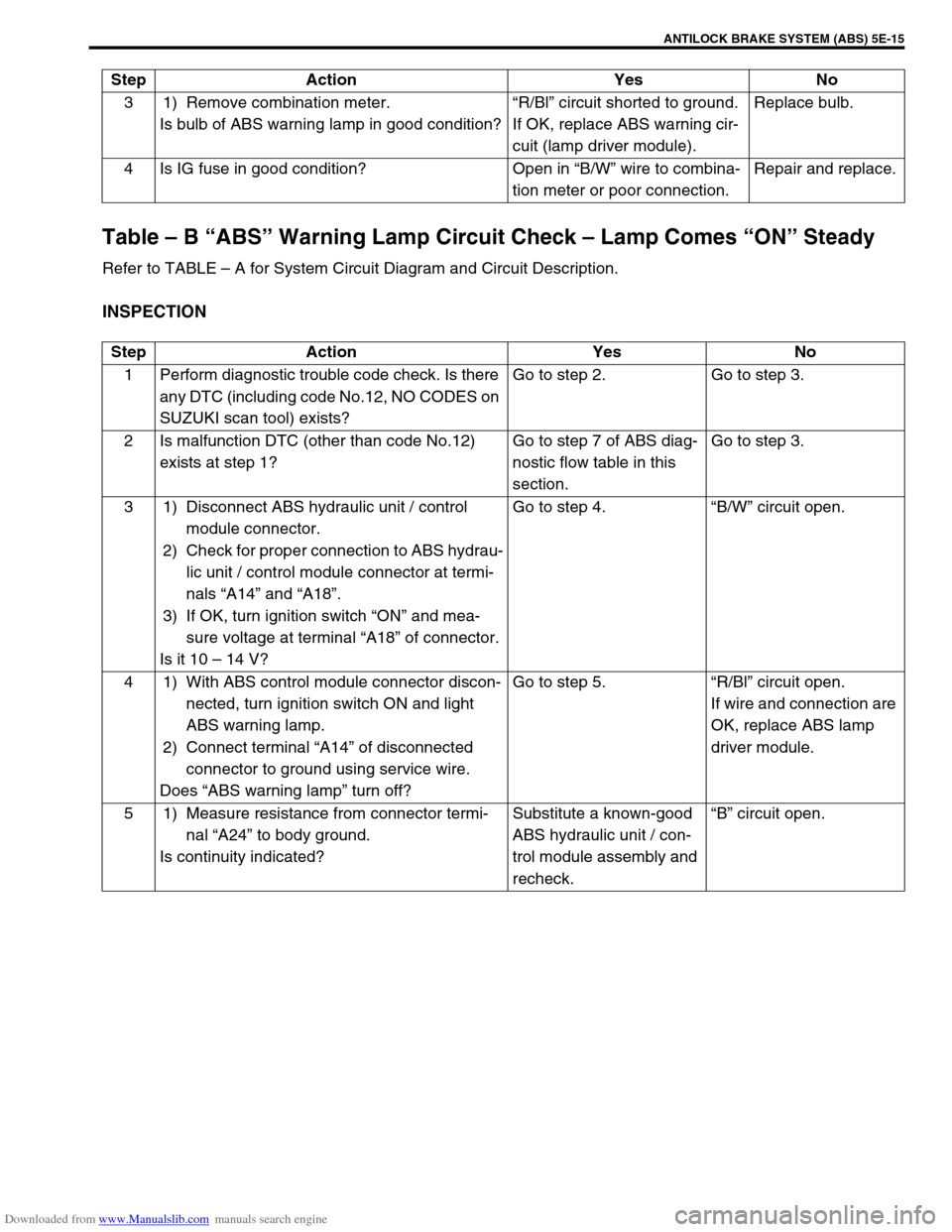
Table – B “ABS” Warning Lamp Circuit Check – Lamp Comes “ON” Steady
Refer to TABLE – A for System Circuit Diagram and Circuit Description.
INSPECTION
3 1) Remove combination meter.
Is bulb of ABS warning lamp in good condition?“R/Bl” circuit shorted to ground.
If OK, replace ABS warning cir-
cuit (lamp driver module).Replace bulb.
4 Is IG fuse in good condition? Open in “B/W” wire to combina-
tion meter or poor connection.Repair and replace. Step Action Yes No
Step Action Yes No
1 Perform diagnostic trouble code check. Is there
any DTC (including code No.12, NO CODES on
SUZUKI scan tool) exists?Go to step 2. Go to step 3.
2 Is malfunction DTC (other than code No.12)
exists at step 1?Go to step 7 of ABS diag-
nostic flow table in this
section.Go to step 3.
3 1) Disconnect ABS hydraulic unit / control
module connector.
2) Check for proper connection to ABS hydrau-
lic unit / control module connector at termi-
nals “A14” and “A18”.
3) If OK, turn ignition switch “ON” and mea-
sure voltage at terminal “A18” of connector.
Is it 10 – 14 V?Go to step 4.“B/W” circuit open.
4 1) With ABS control module connector discon-
nected, turn ignition switch ON and light
ABS warning lamp.
2) Connect terminal “A14” of disconnected
connector to ground using service wire.
Does “ABS warning lamp” turn off?Go to step 5.“R/Bl” circuit open.
If wire and connection are
OK, replace ABS lamp
driver module.
5 1) Measure resistance from connector termi-
nal “A24” to body ground.
Is continuity indicated?Substitute a known-good
ABS hydraulic unit / con-
trol module assembly and
recheck.“B” circuit open.
Page 385 of 687
Downloaded from www.Manualslib.com manuals search engine 6-28 ENGINE GENERAL INFORMATION AND DIAGNOSIS
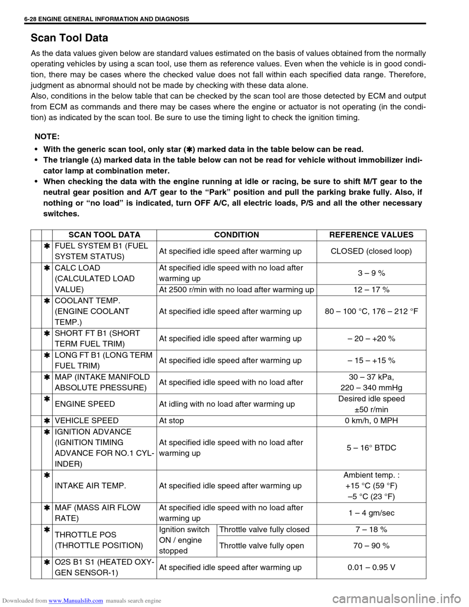
Scan Tool Data
As the data values given below are standard values estimated on the basis of values obtained from the normally
operating vehicles by using a scan tool, use them as reference values. Even when the vehicle is in good condi-
tion, there may be cases where the checked value does not fall within each specified data range. Therefore,
judgment as abnormal should not be made by checking with these data alone.
Also, conditions in the below table that can be checked by the scan tool are those detected by ECM and output
from ECM as commands and there may be cases where the engine or actuator is not operating (in the condi-
tion) as indicated by the scan tool. Be sure to use the timing light to check the ignition timing.
NOTE:
With the generic scan tool, only star (
✱
✱✱ ✱) marked data in the table below can be read.
The triangle (
∆
∆∆ ∆) marked data in the table below can not be read for vehicle without immobilizer indi-
cator lamp at combination meter.
When checking the data with the engine running at idle or racing, be sure to shift M/T gear to the
neutral gear position and A/T gear to the “Park” position and pull the parking brake fully. Also, if
nothing or “no load” is indicated, turn OFF A/C, all electric loads, P/S and all the other necessary
switches.
SCAN TOOL DATA CONDITION REFERENCE VALUES
✱
✱✱ ✱FUEL SYSTEM B1 (FUEL
SYSTEM STATUS)At specified idle speed after warming up CLOSED (closed loop)
✱
✱✱ ✱
CALC LOAD
(CALCULATED LOAD
VALUE)At specified idle speed with no load after
warming up3 – 9 %
At 2500 r/min with no load after warming up 12 – 17 %
✱
✱✱ ✱COOLANT TEMP.
(ENGINE COOLANT
TEMP.)At specified idle speed after warming up 80 – 100 °C, 176 – 212 °F
✱
✱✱ ✱SHORT FT B1 (SHORT
TERM FUEL TRIM)At specified idle speed after warming up– 20 – +20 %
✱
✱✱ ✱LONG FT B1 (LONG TERM
FUEL TRIM)At specified idle speed after warming up– 15 – +15 %
✱
✱✱ ✱MAP (INTAKE MANIFOLD
ABSOLUTE PRESSURE)At specified idle speed with no load after30 – 37 kPa,
220 – 340 mmHg
✱
✱✱ ✱
ENGINE SPEED At idling with no load after warming upDesired idle speed
±50 r/min
✱
✱✱ ✱VEHICLE SPEED At stop 0 km/h, 0 MPH
✱
✱✱ ✱IGNITION ADVANCE
(IGNITION TIMING
ADVANCE FOR NO.1 CYL-
INDER)At specified idle speed with no load after
warming up5 – 16° BTDC
✱
✱✱ ✱
INTAKE AIR TEMP. At specified idle speed after warming upAmbient temp. :
+15 °C (59 °F)
–5 °C (23 °F)
✱
✱✱ ✱MAF (MASS AIR FLOW
RATE)At specified idle speed with no load after
warming up1 – 4 gm/sec
✱
✱✱ ✱
THROTTLE POS
(THROTTLE POSITION)Ignition switch
ON / engine
stoppedThrottle valve fully closed 7 – 18 %
Throttle valve fully open 70 – 90 %
✱
✱✱ ✱O2S B1 S1 (HEATED OXY-
GEN SENSOR-1)At specified idle speed after warming up 0.01 – 0.95 V
Page 387 of 687
Downloaded from www.Manualslib.com manuals search engine 6-30 ENGINE GENERAL INFORMATION AND DIAGNOSIS
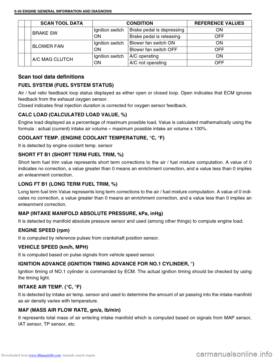
Scan tool data definitions
FUEL SYSTEM (FUEL SYSTEM STATUS)
Air / fuel ratio feedback loop status displayed as either open or closed loop. Open indicates that ECM ignores
feedback from the exhaust oxygen sensor.
Closed indicates final injection duration is corrected for oxygen sensor feedback.
CALC LOAD (CALCULATED LOAD VALUE, %)
Engine load displayed as a percentage of maximum possible load. Value is calculated mathematically using the
formula : actual (current) intake air volume ÷ maximum possible intake air volume x 100%.
COOLANT TEMP. (ENGINE COOLANT TEMPERATURE, °C, °F)
It is detected by engine coolant temp. sensor
SHORT FT B1 (SHORT TERM FUEL TRIM, %)
Short term fuel trim value represents short term corrections to the air / fuel mixture computation. A value of 0
indicates no correction, a value greater than 0 means an enrichment correction, and a value less than 0 implies
an enleanment correction.
LONG FT B1 (LONG TERM FUEL TRIM, %)
Long term fuel trim Value represents long term corrections to the air / fuel mixture computation. A value of 0 indi-
cates no correction, a value greater than 0 means an enrichment correction, and a value less than 0 implies an
enleanment correction.
MAP (INTAKE MANIFOLD ABSOLUTE PRESSURE, kPa, inHg)
It is detected by manifold absolute pressure sensor and used (among other things) to compute engine load.
ENGINE SPEED (rpm)
It is computed by reference pulses from crankshaft position sensor.
VEHICLE SPEED (km/h, MPH)
It is computed based on pulse signals from vehicle speed sensor.
IGNITION ADVANCE (IGNITION TIMING ADVANCE FOR NO.1 CYLINDER, °)
Ignition timing of NO.1 cylinder is commanded by ECM. The actual ignition timing should be checked by using
the timing light.
INTAKE AIR TEMP. (°C, °F)
It is detected by intake air temp. sensor and used to determine the amount of air passing into the intake manifold
as air density varies with temperature.
MAF (MASS AIR FLOW RATE, gm/s, lb/min)
It represents total mass of air entering intake manifold which is computed based on signals from MAP sensor,
IAT sensor, TP sensor, etc.BRAKE SWIgnition switch
ONBrake pedal is depressing ON
Brake pedal is releasing OFF
BLOWER FANIgnition switch
ONBlower fan switch ON ON
Blower fan switch OFF OFF
A/C MAG CLUTCHIgnition switch
ONA/C operating ON
A/C not operating OFF SCAN TOOL DATA CONDITION REFERENCE VALUES
Page 620 of 687
Downloaded from www.Manualslib.com manuals search engine ENGINE AND EMISSION CONTROL SYSTEM 6E-15
On-Vehicle Service
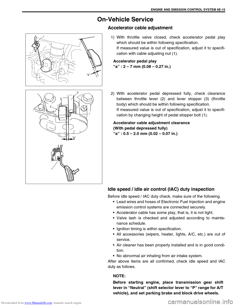
Accelerator cable adjustment
1) With throttle valve closed, check accelerator pedal play
which should be within following specification.
If measured value is out of specification, adjust it to specifi-
cation with cable adjusting nut (1).
Accelerator pedal play
“a” : 2 – 7 mm (0.08 – 0.27 in.)
2) With accelerator pedal depressed fully, check clearance
between throttle lever (2) and lever stopper (3) (throttle
body) which should be within following specification.
If measured value is out of specification, adjust it to specifi-
cation by changing height of pedal stopper bolt (1).
Accelerator cable adjustment clearance
(With pedal depressed fully)
“a” : 0.5 – 2.0 mm (0.02 – 0.07 in.)
Idle speed / idle air control (IAC) duty inspection
Before idle speed / IAC duty check, make sure of the following.
Lead wires and hoses of Electronic Fuel Injection and engine
emission control systems are connected securely.
Accelerator cable has some play, that is, it is not tight.
Valve lash is checked and adjusted according to mainte-
nance schedule.
Ignition timing is within specification.
All accessories (wipers, heater, lights, A/C, etc.) are out of
service.
Air cleaner has been properly installed and is in good condi-
tion.
No abnormal air inhaling from air intake system.
After above items are all confirmed, check idle speed and IAC
duty as follows.
NOTE:
Before starting engine, place transmission gear shift
lever in “Neutral” (shift selector lever to “P” range for A/T
vehicle), and set parking brake and block drive wheels.
Page 677 of 687
Downloaded from www.Manualslib.com manuals search engine 6H-10 CHARGING SYSTEM
1) Set parking brake and place automatic transmission in
PARK (NEUTRAL on manual transmission). Turn off ignition,
turn off lights and all other electrical loads.
2) Check electrolyte level. If it is below low level line, add dis-
tilled water.
3) Attach end of one jumper cable to positive terminal of
booster battery and the other end of the same cable to posi-
tive terminal of discharged battery. (Use 12-volt battery only
to jump start engine).
4) Attach one end of the remaining negative cable to negative
terminal of booster battery, and the other end to a solid
engine ground (such as exhaust manifold) at least 45 cm (18
in.) away from battery of vehicle being started.
5) Start engine of vehicle with booster battery and turn off elec-
trical accessories. Then start engine of the vehicle with dis-
charged battery.
6) Disconnect jumper cables in the exact reverse order.
WITH CHARGING EQUIPMENT
WARNING:
Departure from these conditions or procedure
described below could result in:
–Serious personal injury (particularly to eyes) or
property damage from such causes as battery explo-
sion, battery acid, or electrical burns.
–Damage to electronic components of either vehicle.
Remove rings, watches, and other jewelry. Wear
approved eye protection.
Be careful so that metal tools or jumper cables do not
contact positive battery terminal (or metal in contact
with it) and any other metal on vehicle, because a short
circuit could occur.
WARNING:
Do not connect negative cable directly to negative termi-
nal of dead battery.
CAUTION:
When jump starting engine with charging equipment, be
sure equipment used is 12-volt and negative ground. Do
not use 24-volt charging equipment. Using such equip-
ment can cause serious damage to electrical system or
electronic parts.