egr SUZUKI JIMNY 2005 3.G Service Owner's Manual
[x] Cancel search | Manufacturer: SUZUKI, Model Year: 2005, Model line: JIMNY, Model: SUZUKI JIMNY 2005 3.GPages: 687, PDF Size: 13.38 MB
Page 430 of 687

Downloaded from www.Manualslib.com manuals search engine ENGINE GENERAL INFORMATION AND DIAGNOSIS 6-73
DTC CONFIRMATION PROCEDURE
1) Turn ignition switch OFF.
2) Clear DTC with ignition switch ON.
3) Check vehicle and environmental condition for :
–Altitude (barometric pressure) : 2400 m, 8000 ft or less (560 mmHg, 75 kPa or more)
–Ambient temp. : –10 °C, 14 °F or higher
–Intake air temp. : 70 °C, 158 °F or lower
–Engine coolant temp. : – 10 – 110 °C, 14 – 230 °F
4) Start engine and keep it at idle for 2 min. or more.
5) Check DTC in “DTC” mode and pending DTC in “ON BOARD TEST” or “PENDING DTC” mode.
6) If DTC is not detected at idle, consult usual driving based on information obtained in “Customer complaint
analysis” and “Freeze frame data check”.
INSPECTION
DTC DETECTING CONDITION POSSIBLE CAUSE
Engine under other than high revolution condition
Not on rough road
Engine speed changing rate (below specified value)
Manifold absolute pressure changing rate (below
specified value)
Throttle opening changing rate (below specified
value)
Misfire rate per 200 or 1000 engine revolutions (how
much and how often crankshaft revolution speed
changes) is higher than specified valueEngine overheating
Vacuum leaks (air inhaling) from air intake system
Ignition system malfunction (spark plug(s), high-
tension cord(s), ignition coil assembly)
Fuel pressure out of specification
Fuel injector malfunction (clogged or leakage)
Engine compression out of specification
Valve lash (clearance) out of specification
Manifold absolute pressure sensor malfunction
Engine coolant temp. sensor malfunction
PCV valve malfunction
EVAP control system malfunction
EGR system malfunction
NOTE:
Among different types of random misfire, if misfire occurs at cylinders 1 and 4 or cylinders 3 and 2
simultaneously, it may not possible to reconfirm DTC by using the following DTC confirmation proce-
dure. When diagnosing the trouble of DTC P0300 (Random misfire detected) of the engine which is
apparently misfiring, even if DTC P0300 cannot be reconfirmed by using the following DTC confirma-
tion procedure, proceed to the following Diag. Flow Table.
WARNING:
When performing a road test, select a place where there is no traffic or possibility of a traffic acci-
dent and be very careful during testing to avoid occurrence of an accident.
Road test should be carried out with 2 persons, a driver and a tester.
Step Action Yes No
1Was “Engine Diag. Flow Table” performed? Go to Step 2. Go to “Engine
Diag. Flow Table”.
2 Is there DTC other than Fuel system (DTC P0171/
P0172) and misfire (DTC P0300 – P0304)?Go to applicable DTC
Diag. Flow Table.Go to Step 3.
Page 442 of 687

Downloaded from www.Manualslib.com manuals search engine ENGINE GENERAL INFORMATION AND DIAGNOSIS 6-85
DTC P0400 Exhaust Gas Recirculation Flow Malfunction
CIRCUIT DESCRIPTION
DTC CONFIRMATION PROCEDURE
1) Turn ignition switch OFF.
Clear DTC with ignition switch ON, check vehicle and environmental condition for :
–Altitude (barometric pressure) : 2400 m, 8000 ft or less (560 mmHg, 75 kPa or more)
–Ambient temp. : –10 °C, 14 °F or higher
–Intake air temp. : 70 °C, 122 °F or lower
1. EGR valve
DTC DETECTING CONDITION POSSIBLE CAUSE
While running at specified vehicle speed after engine warm-up
During deceleration (engine speed high with closed throttle position
ON) in which fuel cut is involved, difference in intake manifold absolute
pressure between when EGR valve is opened at specified value and
when it is closed is larger or smaller than specified value.
✱
✱✱ ✱2 driving cycle detection logic, monitoring once / 1 drivingEGR valve or its circuit
EGR passage
ECM
WARNING:
When performing a road test, select a place where there is no traffic or possibility of a traffic acci-
dent and be very careful during testing to avoid occurrence of an accident.
Road test should be carried out with 2 persons, a driver and a tester, on a level road.
Page 443 of 687

Downloaded from www.Manualslib.com manuals search engine 6-86 ENGINE GENERAL INFORMATION AND DIAGNOSIS
2) Start engine and warm it up to normal operating temperature (70 – 110 °C, 158 – 230 °F) and run it at idle
for 5 min.
3) Increase vehicle speed to 50 – 55 mph, 80 – 88 km/h in 5th gear or in “D” range.
4) Hold throttle valve at that opening position for 2 min. or longer.
5) Increase engine speed to 4000 r/min. in 3rd gear or in “2” range.
6) Release accelerator pedal and with engine brake applied, keep vehicle coasting (fuel cut condition) till
engine speed reaches 1500 r/min.
7) Stop vehicle (don’t turn ignition switch OFF) and confirm test results according to following “Test Result Con-
firmation Flow Table.”
Test Result Confirmation Flow Table
INSPECTION
Step Action Yes No
1 Check DTC in “DTC” mode and pending DTC in
“ON BOARD TEST”.
Is DTC or pending DTC displayed?Proceed to applicable
DTC flow table.Go to Step 2.
2 Set scan tool to “READINESS TESTS” mode
and check if testing has been completed.
Is test completed?No DTC is detected.
(Confirmation test is com-
pleted)Repeat DTC confirmation
procedure.
Step Action Yes No
1Was “Engine Diag. Flow Table” performed? Go to Step 2. Go to “Engine Diag. Flow
Table”.
2 1) Turn ignition switch ON.
2) Does EGR stepper motor operation for 0.6
second after ignition switch OFF?Go to Step 3. Go to Step 6.
3 With ignition switch at OFF, check voltage
between E19-28, 17, 29, 18 terminals of ECM
and body ground. See Fig. 2.
Is voltage about 0 V?Go to Step 4. Go to Step 8.
Page 444 of 687
![SUZUKI JIMNY 2005 3.G Service Owners Manual Downloaded from www.Manualslib.com manuals search engine ENGINE GENERAL INFORMATION AND DIAGNOSIS 6-87
[A] Fig. 1 for Step 7 / [B] Fig. 2 for Step 3 and 44 With ignition switch at ON, check voltage
b SUZUKI JIMNY 2005 3.G Service Owners Manual Downloaded from www.Manualslib.com manuals search engine ENGINE GENERAL INFORMATION AND DIAGNOSIS 6-87
[A] Fig. 1 for Step 7 / [B] Fig. 2 for Step 3 and 44 With ignition switch at ON, check voltage
b](/img/20/7588/w960_7588-443.png)
Downloaded from www.Manualslib.com manuals search engine ENGINE GENERAL INFORMATION AND DIAGNOSIS 6-87
[A] Fig. 1 for Step 7 / [B] Fig. 2 for Step 3 and 44 With ignition switch at ON, check voltage
between E19-28, 17, 29, 18 terminals of ECM
and body ground. See Fig. 2.
Is voltage within 10 – 14 V?Go to Step 5. Go to Step 8.
5 Do you have SUZUKI scan tool? Go to Step 6. Stuck or faulty EGR valve
or clogged EGR gas pas-
sage.
If all above are OK, sub-
stitute a known-good
ECM and recheck.
6 Check EGR system referring to “EGR System”
in Section 6E.
Is check result satisfactory?Substitute a known-good
ECM and recheck.Stuck or faulty EGR valve
or clogged EGR gas pas-
sage.
7 1) Disconnect EGR valve connector with igni-
tion switch OFF.
2) Check voltage between “Bl/B” wire terminal
(2) of EGR valve connector (1) and body
ground with ignition switch ON. See Fig. 1.
3) Are they about 10 – 14 V?Go to Step 3.“Bl/B” wire open or short.
8 Check EGR valve referring to “EGR System” in
Section 6E.
Is it good condition?EGR valve harness
(“Gr/B”, “Gr/Bl”, “Gr/R” or
“Gr” wire) open or short or
poor connector connec-
tion (EGR valve connec-
tor, E19-28, 17, 29, 18) If
wire harness and connec-
tion are OK, substitute a
known-good ECM and
recheck.Faulty EGR valve. Step Action Yes No
Page 499 of 687
Downloaded from www.Manualslib.com manuals search engine 6A1-18 ENGINE MECHANICAL (M13 ENGINE)
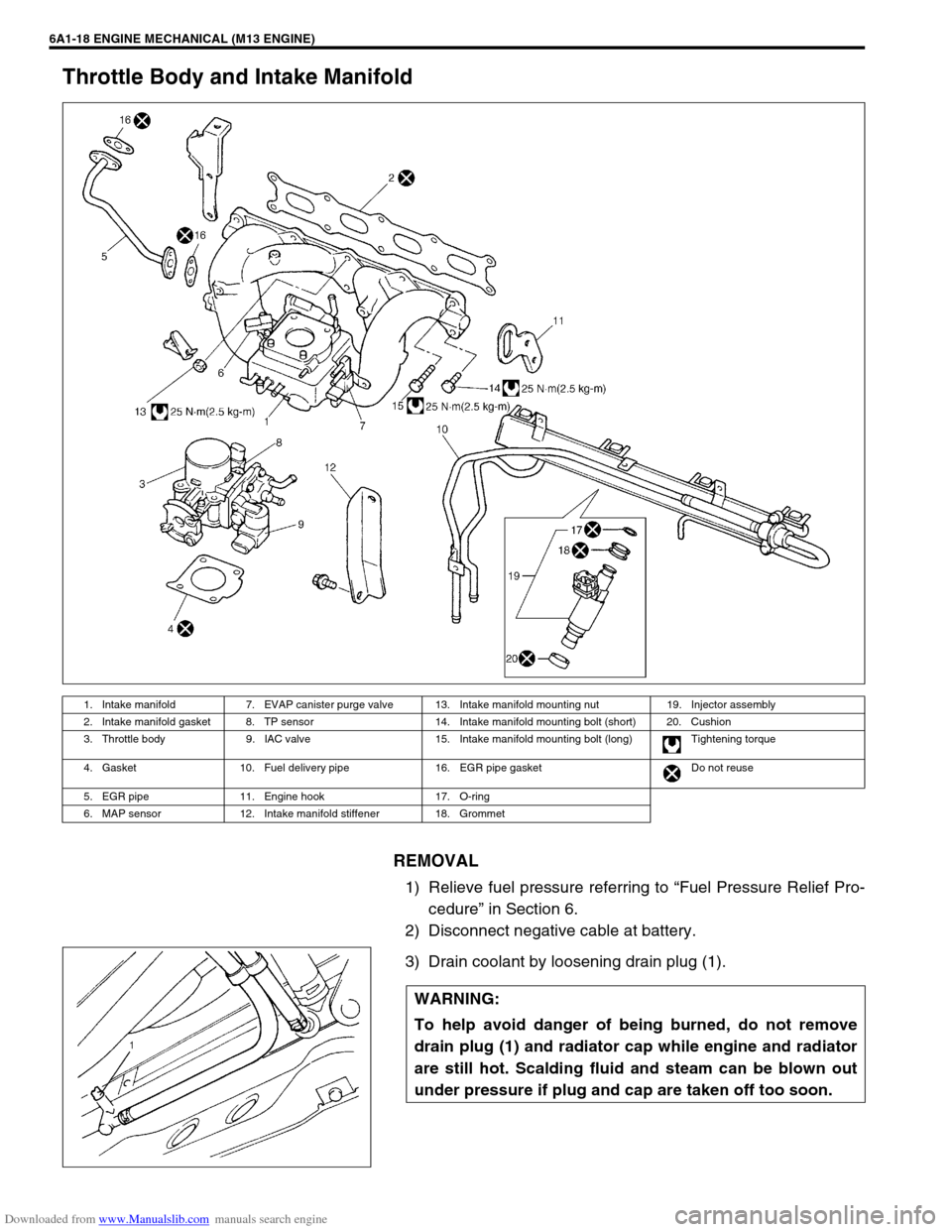
Throttle Body and Intake Manifold
REMOVAL
1) Relieve fuel pressure referring to “Fuel Pressure Relief Pro-
cedure” in Section 6.
2) Disconnect negative cable at battery.
3) Drain coolant by loosening drain plug (1).
1. Intake manifold 7. EVAP canister purge valve 13. Intake manifold mounting nut 19. Injector assembly
2. Intake manifold gasket 8. TP sensor 14. Intake manifold mounting bolt (short) 20. Cushion
3. Throttle body 9. IAC valve 15. Intake manifold mounting bolt (long) Tightening torque
4. Gasket 10. Fuel delivery pipe 16. EGR pipe gasket Do not reuse
5. EGR pipe 11. Engine hook 17. O-ring
6. MAP sensor 12. Intake manifold stiffener 18. Grommet
WARNING:
To help avoid danger of being burned, do not remove
drain plug (1) and radiator cap while engine and radiator
are still hot. Scalding fluid and steam can be blown out
under pressure if plug and cap are taken off too soon.
Page 500 of 687
Downloaded from www.Manualslib.com manuals search engine ENGINE MECHANICAL (M13 ENGINE) 6A1-19
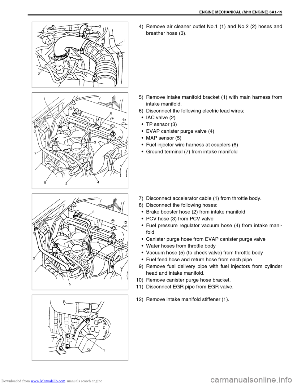
4) Remove air cleaner outlet No.1 (1) and No.2 (2) hoses and
breather hose (3).
5) Remove intake manifold bracket (1) with main harness from
intake manifold.
6) Disconnect the following electric lead wires:
IAC valve (2)
TP sensor (3)
EVAP canister purge valve (4)
MAP sensor (5)
Fuel injector wire harness at couplers (6)
Ground terminal (7) from intake manifold
7) Disconnect accelerator cable (1) from throttle body.
8) Disconnect the following hoses:
Brake booster hose (2) from intake manifold
PCV hose (3) from PCV valve
Fuel pressure regulator vacuum hose (4) from intake mani-
fold
Canister purge hose from EVAP canister purge valve
Water hoses from throttle body
Vacuum hose (5) (to check valve) from throttle body
Fuel feed hose and return hose from each pipe
9) Remove fuel delivery pipe with fuel injectors from cylinder
head and intake manifold.
10) Remove canister purge hose bracket.
11) Disconnect EGR pipe from EGR valve.
12) Remove intake manifold stiffener (1).
Page 501 of 687
Downloaded from www.Manualslib.com manuals search engine 6A1-20 ENGINE MECHANICAL (M13 ENGINE)
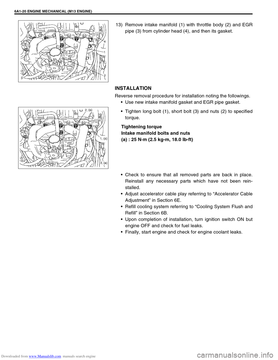
13) Remove intake manifold (1) with throttle body (2) and EGR
pipe (3) from cylinder head (4), and then its gasket.
INSTALLATION
Reverse removal procedure for installation noting the followings.
Use new intake manifold gasket and EGR pipe gasket.
Tighten long bolt (1), short bolt (3) and nuts (2) to specified
torque.
Tightening torque
Intake manifold bolts and nuts
(a) : 25 N·m (2.5 kg-m, 18.0 lb-ft)
Check to ensure that all removed parts are back in place.
Reinstall any necessary parts which have not been rein-
stalled.
Adjust accelerator cable play referring to “Accelerator Cable
Adjustment” in Section 6E.
Refill cooling system referring to “Cooling System Flush and
Refill” in Section 6B.
Upon completion of installation, turn ignition switch ON but
engine OFF and check for fuel leaks.
Finally, start engine and check for engine coolant leaks.
Page 530 of 687
Downloaded from www.Manualslib.com manuals search engine ENGINE MECHANICAL (M13 ENGINE) 6A1-49
REMOVAL
1) Relieve fuel pressure referring to “Fuel Pressure Relief Pro-
cedure” in Section 6.
2) Disconnect negative cable at battery.
3) Drain engine oil.
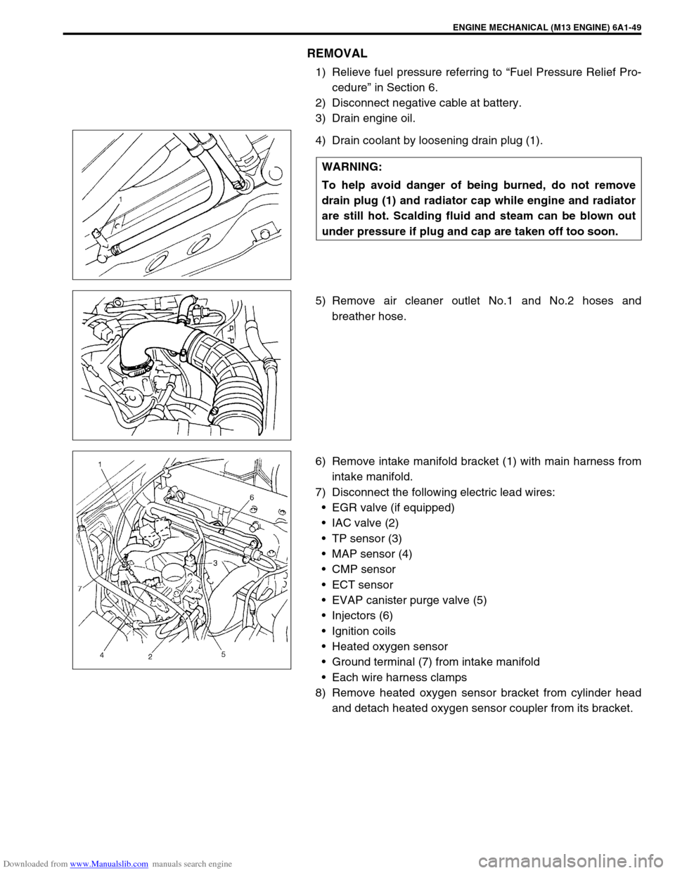
4) Drain coolant by loosening drain plug (1).
5) Remove air cleaner outlet No.1 and No.2 hoses and
breather hose.
6) Remove intake manifold bracket (1) with main harness from
intake manifold.
7) Disconnect the following electric lead wires:
EGR valve (if equipped)
IAC valve (2)
TP sensor (3)
MAP sensor (4)
CMP sensor
ECT sensor
EVAP canister purge valve (5)
Injectors (6)
Ignition coils
Heated oxygen sensor
Ground terminal (7) from intake manifold
Each wire harness clamps
8) Remove heated oxygen sensor bracket from cylinder head
and detach heated oxygen sensor coupler from its bracket. WARNING:
To help avoid danger of being burned, do not remove
drain plug (1) and radiator cap while engine and radiator
are still hot. Scalding fluid and steam can be blown out
under pressure if plug and cap are taken off too soon.
Page 536 of 687
Downloaded from www.Manualslib.com manuals search engine ENGINE MECHANICAL (M13 ENGINE) 6A1-55
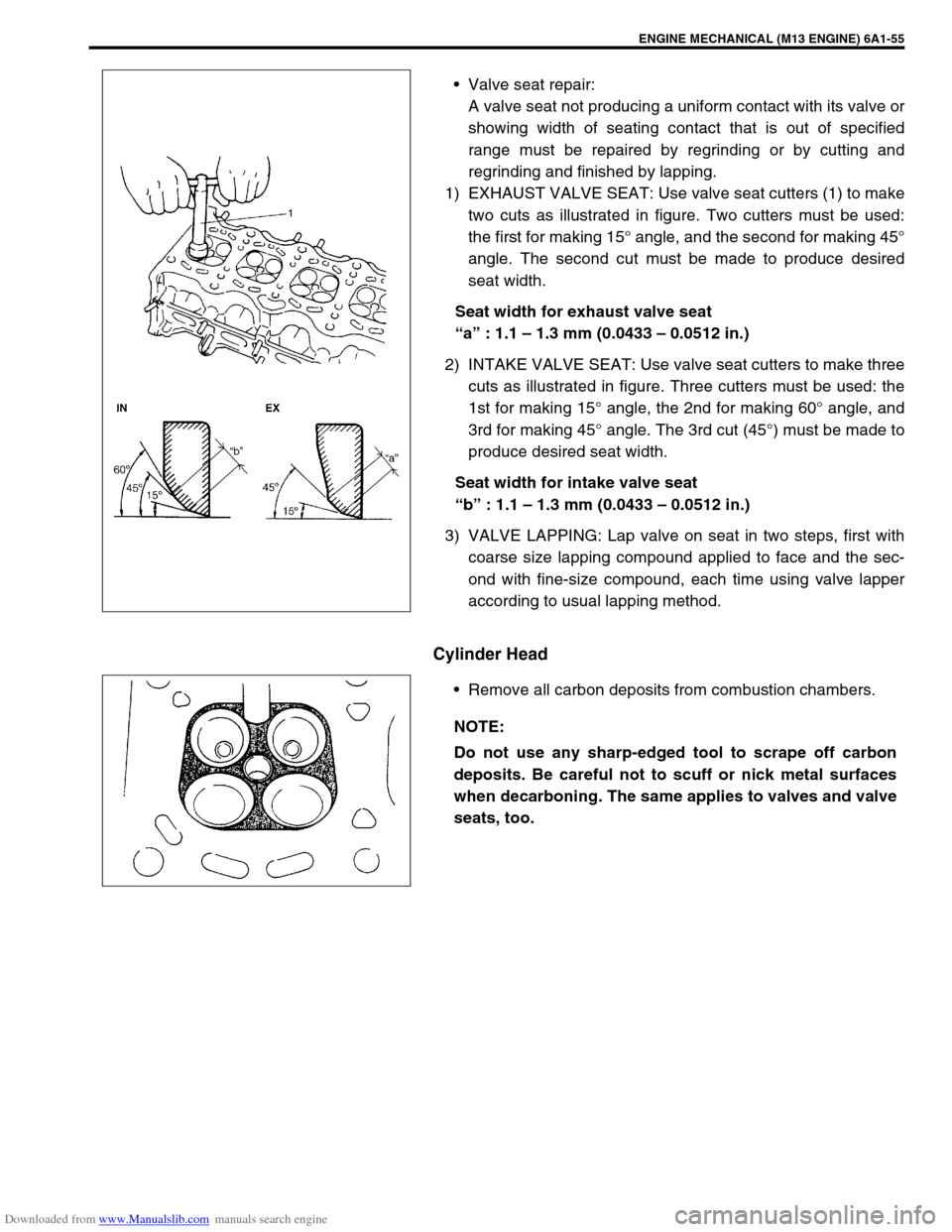
Valve seat repair:
A valve seat not producing a uniform contact with its valve or
showing width of seating contact that is out of specified
range must be repaired by regrinding or by cutting and
regrinding and finished by lapping.
1) EXHAUST VALVE SEAT: Use valve seat cutters (1) to make
two cuts as illustrated in figure. Two cutters must be used:
the first for making 15° angle, and the second for making 45°
angle. The second cut must be made to produce desired
seat width.
Seat width for exhaust valve seat
“a” : 1.1 – 1.3 mm (0.0433 – 0.0512 in.)
2) INTAKE VALVE SEAT: Use valve seat cutters to make three
cuts as illustrated in figure. Three cutters must be used: the
1st for making 15° angle, the 2nd for making 60° angle, and
3rd for making 45° angle. The 3rd cut (45°) must be made to
produce desired seat width.
Seat width for intake valve seat
“b” : 1.1 – 1.3 mm (0.0433 – 0.0512 in.)
3) VALVE LAPPING: Lap valve on seat in two steps, first with
coarse size lapping compound applied to face and the sec-
ond with fine-size compound, each time using valve lapper
according to usual lapping method.
Cylinder Head
Remove all carbon deposits from combustion chambers.
NOTE:
Do not use any sharp-edged tool to scrape off carbon
deposits. Be careful not to scuff or nick metal surfaces
when decarboning. The same applies to valves and valve
seats, too.
Page 548 of 687
Downloaded from www.Manualslib.com manuals search engine ENGINE MECHANICAL (M13 ENGINE) 6A1-67
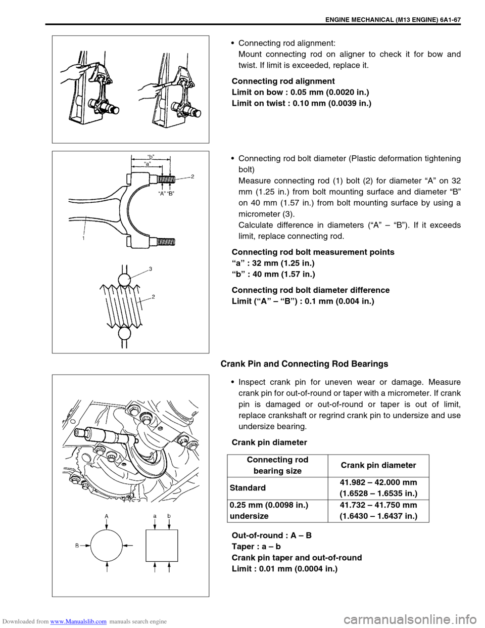
Connecting rod alignment:
Mount connecting rod on aligner to check it for bow and
twist. If limit is exceeded, replace it.
Connecting rod alignment
Limit on bow : 0.05 mm (0.0020 in.)
Limit on twist : 0.10 mm (0.0039 in.)
Connecting rod bolt diameter (Plastic deformation tightening
bolt)
Measure connecting rod (1) bolt (2) for diameter “A” on 32
mm (1.25 in.) from bolt mounting surface and diameter “B”
on 40 mm (1.57 in.) from bolt mounting surface by using a
micrometer (3).
Calculate difference in diameters (“A” – “B”). If it exceeds
limit, replace connecting rod.
Connecting rod bolt measurement points
“a” : 32 mm (1.25 in.)
“b” : 40 mm (1.57 in.)
Connecting rod bolt diameter difference
Limit (“A” – “B”) : 0.1 mm (0.004 in.)
Crank Pin and Connecting Rod Bearings
Inspect crank pin for uneven wear or damage. Measure
crank pin for out-of-round or taper with a micrometer. If crank
pin is damaged or out-of-round or taper is out of limit,
replace crankshaft or regrind crank pin to undersize and use
undersize bearing.
Crank pin diameter
Out-of-round : A – B
Taper : a – b
Crank pin taper and out-of-round
Limit : 0.01 mm (0.0004 in.)
Connecting rod
bearing sizeCrank pin diameter
Standard41.982 – 42.000 mm
(1.6528 – 1.6535 in.)
0.25 mm (0.0098 in.)
undersize41.732 – 41.750 mm
(1.6430 – 1.6437 in.)