throttle body SUZUKI JIMNY 2005 3.G Service Owner's Manual
[x] Cancel search | Manufacturer: SUZUKI, Model Year: 2005, Model line: JIMNY, Model: SUZUKI JIMNY 2005 3.GPages: 687, PDF Size: 13.38 MB
Page 625 of 687

Downloaded from www.Manualslib.com manuals search engine 6E-20 ENGINE AND EMISSION CONTROL SYSTEM
INSTALLATION
1) Clean mating surfaces and install throttle body gasket to
intake manifold.
Use new gasket.
2) Connect engine coolant hoses.
3) Install throttle body (1) to intake manifold.
4) Connect connectors to TP sensor (2) and IAC valve (3)
securely.
5) Install air cleaner outlet No.2 hose (1) and pipe.
6) Connect accelerator cable and adjust cable play to specifica-
tion.
7) Refill cooling system.
8) Connect negative cable at battery.
Page 626 of 687

Downloaded from www.Manualslib.com manuals search engine ENGINE AND EMISSION CONTROL SYSTEM 6E-21
Idle air control valve (IAC valve)
REMOVAL
1) Remove throttle body from intake manifold referring to
“Throttle Body” in this section for removal.
2) Remove IAC valve from throttle body.
INSPECTION
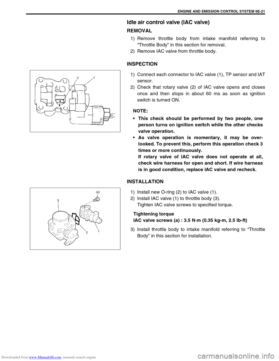
1) Connect each connector to IAC valve (1), TP sensor and IAT
sensor.
2) Check that rotary valve (2) of lAC valve opens and closes
once and then stops in about 60 ms as soon as ignition
switch is turned ON.
INSTALLATION
1) Install new O-ring (2) to IAC valve (1).
2) Install IAC valve (1) to throttle body (3).
Tighten IAC valve screws to specified torque.
Tightening torque
IAC valve screws (a) : 3.5 N·m (0.35 kg-m, 2.5 lb-ft)
3) Install throttle body to intake manifold referring to “Throttle
Body” in this section for installation. NOTE:
This check should be performed by two people, one
person turns on ignition switch while the other checks
valve operation.
As valve operation is momentary, it may be over-
looked. To prevent this, perform this operation check 3
times or more continuously.
If rotary valve of lAC valve does not operate at all,
check wire harness for open and short. If wire harness
is in good condition, replace lAC valve and recheck.
Page 635 of 687

Downloaded from www.Manualslib.com manuals search engine 6E-30 ENGINE AND EMISSION CONTROL SYSTEM
Throttle position sensor (TP sensor)
INSPECTION
1) Disconnect negative cable at battery and connector from TP
sensor.
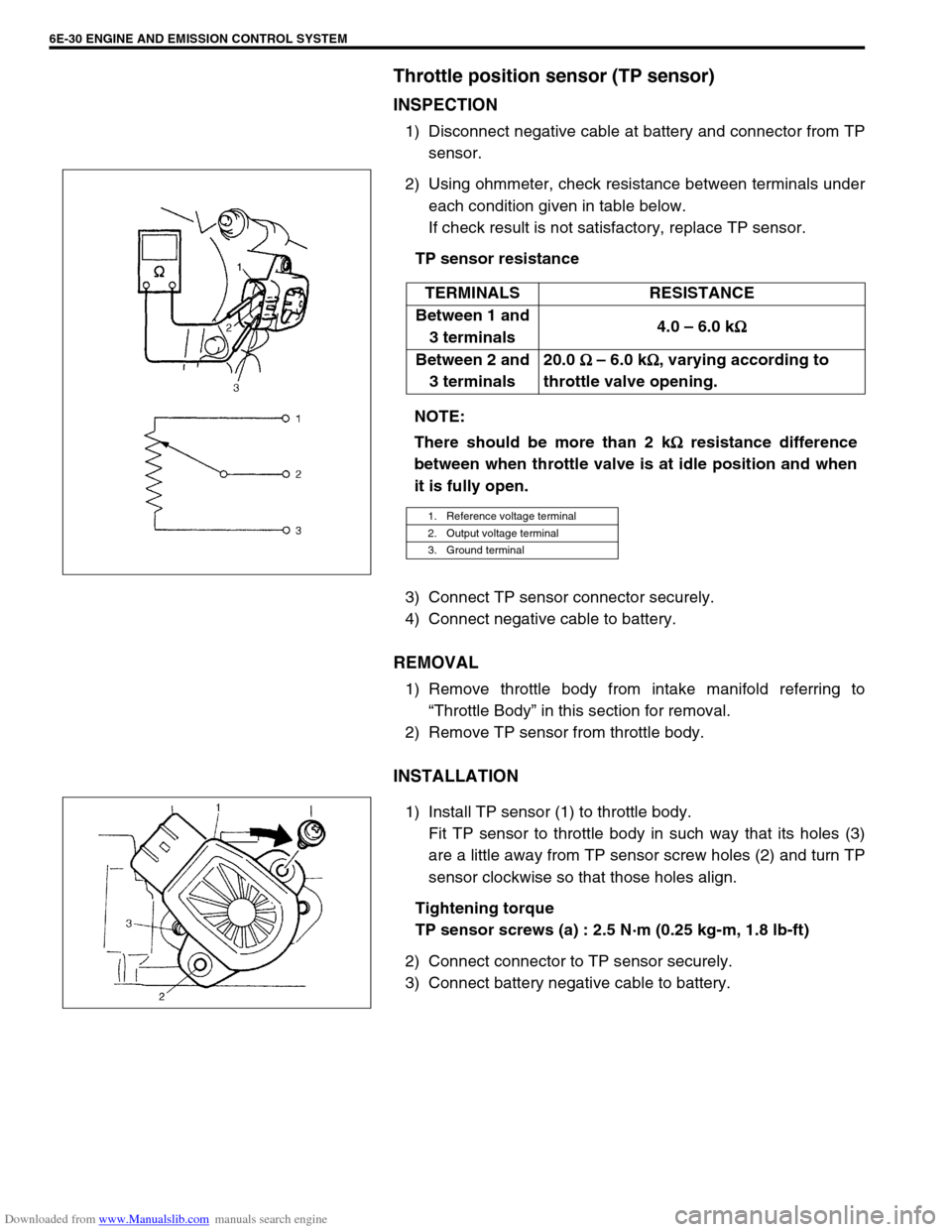
2) Using ohmmeter, check resistance between terminals under
each condition given in table below.
If check result is not satisfactory, replace TP sensor.
TP sensor resistance
3) Connect TP sensor connector securely.
4) Connect negative cable to battery.
REMOVAL
1) Remove throttle body from intake manifold referring to
“Throttle Body” in this section for removal.
2) Remove TP sensor from throttle body.
INSTALLATION
1) Install TP sensor (1) to throttle body.
Fit TP sensor to throttle body in such way that its holes (3)
are a little away from TP sensor screw holes (2) and turn TP
sensor clockwise so that those holes align.
Tightening torque
TP sensor screws (a) : 2.5 N·m (0.25 kg-m, 1.8 lb-ft)
2) Connect connector to TP sensor securely.
3) Connect battery negative cable to battery.TERMINALS RESISTANCE
Between 1 and
3 terminals4.0 – 6.0 k
Ω
ΩΩ Ω
Between 2 and
3 terminals20.0
Ω
ΩΩ Ω – 6.0 k
Ω
ΩΩ Ω, varying according to
throttle valve opening.
NOTE:
There should be more than 2 k
Ω
ΩΩ Ω resistance difference
between when throttle valve is at idle position and when
it is fully open.
1. Reference voltage terminal
2. Output voltage terminal
3. Ground terminal
Page 658 of 687

Downloaded from www.Manualslib.com manuals search engine IGNITION SYSTEM (ELECTRONIC IGNITION SYSTEM 6F-9
5) Fix ignition timing to initial one as follows.
a) When using SUZUKI scan tool:
Select “MISC” mode on SUZUKI scan tool and fix ignition
timing to initial one.
b) Without using SUZUKI scan tool: (vehicle without immobi-
lizer indicator lamp)
Disconnect scan tool from DLC, and connect D and E ter-
minals of monitor connector (1) or E to body ground by
using service wire so that ignition timing is fixed on initial
one.
6) Using timing light (1), check that ignition timing is within
specification.
Initial ignition timing (test switch terminal grounded or
fixed with SUZUKI scan tool)
5
± 3° BTDC at idle speed
Ignition order
1-3-4-2
7) If ignition timing is out of specification, check the followings:
CKP sensor
CKP sensor plate
TP sensor
Test switch signal circuit
VSS
Timing chain cover installation
8) After checking Initial Ignition Timing, release ignition timing
fixation by using SUZUKI scan tool or disconnect service
wire from monitor connector.
9) With engine idling (test switch terminal ungrounded, throttle
opening at closed position and car stopped), check that igni-
tion timing is about 7°–17° BTDC. (Constant variation within
a few degrees from 7°–17° indicates no abnormality but
proves operation of electronic timing control system.) Also,
check that increasing engine speed advances ignition timing.
If above check results are not satisfactory, check CKP sen-
sor, test switch terminal circuit and ECM.