wiring SUZUKI JIMNY 2005 3.G Service Owner's Manual
[x] Cancel search | Manufacturer: SUZUKI, Model Year: 2005, Model line: JIMNY, Model: SUZUKI JIMNY 2005 3.GPages: 687, PDF Size: 13.38 MB
Page 390 of 687

Downloaded from www.Manualslib.com manuals search engine ENGINE GENERAL INFORMATION AND DIAGNOSIS 6-33
Inspection of ECM and Its Circuits
ECM and its circuits can be checked at ECM wiring connectors by
measuring voltage and resistance.
VOLTAGE CHECK
1) Remove ECM from body referring to Section 6E.
2) Check voltage at each terminal of connectors connected.CAUTION:
ECM cannot be checked by itself. It is strictly prohibited
to connect voltmeter or ohmmeter to ECM with connector
disconnected from it.
NOTE:
As each terminal voltage is affected by the battery volt-
age, confirm that it is 11 V or more when ignition switch
is ON.
1. ECM
2. ECM connectors (Viewed from harness side)
Page 401 of 687

Downloaded from www.Manualslib.com manuals search engine 6-44 ENGINE GENERAL INFORMATION AND DIAGNOSIS
Table A-2 Malfunction Indicator Lamp Circuit Check - Lamp Remains “ON”
after Engine Starts
WIRING DIAGRAM / CIRCUIT DESCRIPTION
Refer to table A-1.
INSPECTION
2 ECM Power and Ground Circuit Check
Does engine start?Go to Step 3. Go to “Table A-5 ECM
Power and Ground Circuit
Check”.
If engine is not cranked,
go to “Diagnosis” in Sec-
tion 8G.
3 MIL Circuit Check
1) Turn ignition switch OFF and disconnect
connectors from ECM.
2) Check for proper connection to ECM at ter-
minal E18-2 (Case of TYPE A) (See NOTE)
or E17-9 (Case of TYPE B) (See NOTE).
3) If OK, then using service wire, ground termi-
nal E18-2 (Case of TYPE A) (See NOTE) or
E17-9 (Case of TYPE B) (See NOTE) in
connector disconnected.
Does MIL turn on at ignition switch ON?Substitute a known-good
ECM and recheck.Bulb burned out, “V/Y”
wire circuit open or “P”
wire shorted to ground. Step Action Yes No
Step Action Yes No
1 Diagnostic Trouble Code (DTC) check
1) Check DTC referring to DTC CHECK sec-
tion.
Is there any DTC(s)?Go to Step 2 of “Engine
Diag. Flow Table”.Go to Step 2.
2DTC check
1) Start engine and recheck DTC while engine
running.
Is there any DTC(s)?Go to Step 3.
3 MIL Circuit check
1) Turn OFF ignition switch.
2) Disconnect connectors from ECM.
Does MIL turn ON at ignition switch ON?“V/Y” wire circuit shorted
to ground.Substitute a known-good
ECM and recheck.
Page 402 of 687

Downloaded from www.Manualslib.com manuals search engine ENGINE GENERAL INFORMATION AND DIAGNOSIS 6-45
Table A-3 Malfunction Indicator Lamp Circuit Check - Mil Flashes at Ignition
Switch ON
WIRING DIAGRAM / CIRCUIT DESCRIPTION
Refer to table A-1.
INSPECTION
Table A-4 Malfunction Indicator Lamp Circuit Check - MIL Does Not Flash, Just
Remains ON or Just Remains OFF Even with Grounding Diagnosis Switch
Terminal
WIRING DIAGRAM / CIRCUIT DESCRIPTION
Refer to table A-1.
INSPECTION
Step Action Yes No
1 MIL flashing pattern check :
1) With the ignition switch ON position, check
MIL flashing pattern.
Does MIL flashing pattern indicate DTC (diag-
nostic trouble code)?Go to Step 2. Go to “Diagnosis” in Sec-
tion 8G.
2 Diagnosis switch terminal check :
1) With the ignition switch ON position, check
voltage between E18-14 terminal of ECM
coupler and ground.
Is voltage 4 – 5 V?Substitute a known-good
ECM and recheck.“W/Bl” wire (diagnosis
switch terminal) shorted
to ground circuit.
If OK, substitute a known-
good ECM and recheck.
Step Action Yes No
1 MIL flashing pattern check :
1) With grounding diagnosis switch terminal
and turn the ignition switch ON position,
check voltage between E18-14 terminal of
ECM connector and ground.
Is voltage 0 – 1 V?Go to Step 2.“W/Bl” wire (diagnosis
switch terminal), “B” wire
of monitor connector
open.
If OK, substitute a known-
good ECM and recheck.
2 Test switch terminal circuit check :
1) With the ignition switch ON position, check
voltage between E18-15 terminal of ECM
connector and ground.
Is voltage 4 – 5 V?Substitute a known-good
ECM and recheck.“P” wire (test switch termi-
nal) shorted to ground cir-
cuit.
If OK, substitute a known-
good ECM and recheck.
Page 414 of 687

Downloaded from www.Manualslib.com manuals search engine ENGINE GENERAL INFORMATION AND DIAGNOSIS 6-57
DTC P0121 Throttle Position Circuit Range / Performance Problem
WIRING DIAGRAM
Refer to DTC P0120 section.
CIRCUIT DESCRIPTION
DTC CONFIRMATION PROCEDURE
1) Turn ignition switch OFF. Clear DTC with ignition switch ON, check vehicle and environmental condition for :
–Altitude (barometric pressure) : 2400 m, 8000 ft or less (560 mmHg, 75 kPa or more)
–Ambient temp. : –10 °C, 14 °F or higher
–Intake air temp. : 70 °C, 158 °F or lower
–Engine coolant temp. : 70 °C, 158 °F or higher
2) Warm up engine to normal operating temperature.
3) Increase vehicle speed to 30 – 40 mph, 50 – 60 km/h in 3rd gear or “D” range and hold throttle valve at that
opening position for 1 min.
4) Stop vehicle.
5) Check DTC in “DTC” mode and pending DTC in “ON BOARD TEST” or “PENDING DTC” mode.
INSPECTION
DTC DETECTING CONDITION POSSIBLE CAUSE
After engine warmed up.
Difference between actual throttle opening (detected from TP sensor)
and opening calculated by ECM (Obtained on the basis of engine
speed and intake manifold pressure) in larger than specified value.
✱2 driving cycle detection logic, continuous monitoringTP sensor malfunction
High resistance in the circuit
ECM malfunction
WARNING:
When performing a road test, select a place where there is no traffic or possibility of a traffic acci-
dent and be very careful during testing to avoid occurrence of an accident.
Road test should be carried out with 2 persons, a driver and a tester, on a level road.
Step Action Yes No
1Was “Engine Diag. Flow Table” performed? Go to Step 2. Go to “Engine Diag. Flow
Table”.
2 Is SUZUKI scan tool available? Go to Step 3. Go to Step 4.
3 Check TP Sensor and Its Circuit.
1) Turn ignition switch OFF and connect
SUZUKI scan tool to DLC. See Fig. 1.
2) Turn ignition switch ON and check TP sen-
sor output voltage when throttle valve is at
idle position and fully opened. See Fig. 3.
Dose voltage vary within specified value linearly
as shown in figure?Substitute a known-good
ECM and recheck.Go to Step 5.
Page 418 of 687

Downloaded from www.Manualslib.com manuals search engine ENGINE GENERAL INFORMATION AND DIAGNOSIS 6-61
DTC P0133 Heated Oxygen Sensor (HO2S) Circuit Slow Response (Sensor-1)
WIRING DIAGRAM
Refer to DTC P0130 section.
CIRCUIT DESCRIPTION
Fig. 1
DTC CONFIRMATION PROCEDURE
Refer to DTC P0130 section.
INSPECTION
DTC DETECTING CONDITION POSSIBLE CAUSE
When running at specified idle speed after engine warmed up and
running at specified vehicle speed, response time (time to change
from lean to rich or from rich to lean) of HO2S-1 output voltage is
about 1 sec. at minimum or average time of 1 cycle is 5 sec. at
minimum. See. Fig. 1
✱
✱✱ ✱2 driving cycle detection logic, Monitoring once / 1 driving.Heated oxygen sensor-1 malfunction
Step Action Yes No
1Was “Engine Diag. Flow Table” performed? Go to Step 2. Go to “Engine Diag. Flow
Table”.
2 Is there DTC(s) other than HO2S-1 (DTC
P0133)?Go to applicable DTC
Diag. Flow Table.Replace HO2S-1.
Page 456 of 687

Downloaded from www.Manualslib.com manuals search engine ENGINE GENERAL INFORMATION AND DIAGNOSIS 6-99
DTC P1450 Barometric Pressure Sensor Low / High Input
DTC P1451 Barometric Pressure Sensor Performance Problem
WIRING DIAGRAM / CIRCUIT DESCRIPTION
Barometric pressure sensor is installed in ECM.
DTC CONFIRMATION PROCEDURE
1) Turn ignition switch OFF.
2) Clear DTC with ignition switch ON.
3) Turn ignition switch ON for 2 sec., crank engine for 2 sec. and run it at idle for 1 min.
4) Check pending DTC in “ON BOARD TEST” or “PENDING DTC” mode and DTC in “DTC” mode.
INSPECTION
DTC P1450 :
Substitute a known-good ECM and recheck.
DTC P1451 :
DTC DETECTING CONDITION POSSIBLE CAUSE
DTC P1450 :
Barometric pressure sensor voltage is 4.7 V or higher, or
1.6 V or lowerECM (barometric pressure sensor) malfunc-
tion
DTC P1451 :
Vehicle stopped
Engine cranking
Difference between barometric pressure and intake mani-
fold absolute pressure is 26 kPa, 200 mmHg or more.
Difference between intake manifold absolute pressure at
engine start and pressure after engine start is less than 1.3
kPa, 10 mmHg.
✱
✱✱ ✱2 driving cycle detection logic, monitoring once / 1 driving.ECM (barometric pressure sensor) malfunc-
tion
NOTE:
Note that atmospheric pressure varies depending on weather conditions as well as altitude.
Take that into consideration when performing these check.
Step Action Yes No
1Was “Engine Diag. Flow Table” performed? Go to Step 2. Go to “Engine Diag. Flow
Table”.
2 1) Connect scan tool to DLC with ignition
switch OFF. See Fig.1.
2) Turn ignition switch ON and select “DATA
LIST” mode on scan tool.
3) Check manifold absolute pressure.
Is it barometric pressure (approx. 100 kPa, 760
mmHg) at sea level?Substitute a known-good
ECM and recheck.Go to Step 3.
Page 482 of 687
Downloaded from www.Manualslib.com manuals search engine ENGINE MECHANICAL (M13 ENGINE) 6A1-1
6F1
6G
6H
6K
7A
7A1
7B1
7C1
7D
7E
7F
8A
8C
6A1
8E
9
9
10B
SECTION 6A1
ENGINE MECHANICAL (M13 ENGINE)
CONTENTS
General Description ......................................6A1-2
Engine ......................................................... 6A1-2
Engine Lubrication ...................................... 6A1-3
Diagnosis .......................................................6A1-4
Diagnosis Table .......................................... 6A1-4
Compression Check .................................... 6A1-4
Engine Vacuum Check ................................ 6A1-6
Oil Pressure Check ..................................... 6A1-7
Valve Lash (Clearance) ............................... 6A1-9
On-Vehicle Service......................................6A1-13
Air Cleaner Element .................................. 6A1-13
Air Cleaner Assembly ................................ 6A1-14
Knock Sensor ............................................ 6A1-14
Cylinder Head Cover ................................. 6A1-15
Throttle Body and Intake Manifold ............ 6A1-18
Exhaust Manifold ....................................... 6A1-21Oil Pan and Oil Pump Strainer .................. 6A1-24
Timing Chain Cover .................................. 6A1-28
Oil Pump ................................................... 6A1-33
Timing Chain and Chain Tensioner .......... 6A1-37
Camshaft, Tappet and Shim ..................... 6A1-42
Valves and Cylinder Head ........................ 6A1-48
Pistons, Piston Rings, Connecting
Rods and Cylinders................................... 6A1-62
Engine Mountings ..................................... 6A1-72
Unit Repair Overhaul .................................. 6A1-73
Engine Assembly ...................................... 6A1-73
Main Bearings, Crankshaft and Cylinder
Block ......................................................... 6A1-79
Required Service Material .......................... 6A1-93
Tightening Torque Specification ............... 6A1-93
Special Tool ................................................. 6A1-94
WARNING:
For vehicles equipped with Supplemental Restraint (Air Bag) System:
Service on and around the air bag system components or wiring must be performed only by an
authorized SUZUKI dealer. Refer to “Air Bag System Components and Wiring Location View” under
“General Description” in air bag system section in order to confirm whether you are performing ser-
vice on or near the air bag system components or wiring. Please observe all WARNINGS and “Ser-
vice Precautions” under “On-Vehicle Service” in air bag system section before performing service
on or around the air bag system components or wiring. Failure to follow WARNINGS could result in
unintentional activation of the system or could render the system inoperative. Either of these two
conditions may result in severe injury.
Technical service work must be started at least 90 seconds after the ignition switch is turned to the
“LOCK” position and the negative cable is disconnected from the battery. Otherwise, the system
may be activated by reserve energy in the Sensing and Diagnostic Module (SDM).
Page 606 of 687

Downloaded from www.Manualslib.com manuals search engine ENGINE AND EMISSION CONTROL SYSTEM 6E-1
6F1
6F2
6G
7C1
7D
7E
7A
7A1
7B1
7C1
7D
7E
7F
8A
8B
8C
8D
6H
6E
10
10A
10B
SECTION 6E
ENGINE AND EMISSION CONTROL SYSTEM
CONTENTS
General Description ....................................... 6E-3
Air Intake System ......................................... 6E-5
Fuel Delivery System ................................... 6E-6
Fuel pump ................................................ 6E-6
Electronic Control System ............................ 6E-7
Engine & emission control input / output
table.......................................................... 6E-8
On-Vehicle Service....................................... 6E-15
Accelerator cable adjustment ................. 6E-15
Idle speed / idle air control (IAC) duty
inspection ............................................... 6E-15
Idle mixture inspection / adjustment
(vehicle without heated oxygen
sensor) ................................................... 6E-17
Air Intake System ....................................... 6E-18
Throttle body .......................................... 6E-18
Idle air control valve (IAC valve)............. 6E-21
Fuel Delivery System ................................. 6E-22
Fuel pressure inspection ........................ 6E-22
Fuel pump .............................................. 6E-23
Fuel pressure regulator .......................... 6E-24
Fuel injector ............................................ 6E-25
Electronic Control System .......................... 6E-29Engine control module (ECM) ................ 6E-29
Manifold absolute pressure sensor (MAP
sensor) ................................................... 6E-29
Throttle position sensor (TP sensor) ...... 6E-30
Intake air temperature sensor
(IAT sensor) ........................................... 6E-31
Engine coolant temperature sensor
(ECT sensor) .......................................... 6E-32
Heated oxygen sensor
(Sensor-1 and sensor-2) ........................ 6E-33
Camshaft position sensor....................... 6E-34
Crankshaft position sensor..................... 6E-35
Vehicle speed sensor (VSS) .................. 6E-36
Fuel level sensor (GAUGE).................... 6E-36
Knock sensor ......................................... 6E-36
Main relay, fuel pump relay and A/C
condenser fan control relay .................... 6E-36
Fuel cut operation .................................. 6E-37
A/C condenser fan control system ......... 6E-37
A/C condenser fan ................................. 6E-37
Output signals of throttle valve opening
and engine coolant temp.
(Vehicle with A/T only) ........................... 6E-38
Emission Control System ........................... 6E-38 WARNING:
For vehicles equipped with Supplemental Restraint (Air Bag) System:
Service on and around the air bag system components or wiring must be performed only by an
authorized SUZUKI dealer. Refer to “Air Bag System Components and Wiring Location View” under
“General Description” in air bag system section in order to confirm whether you are performing ser-
vice on or near the air bag system components or wiring. Please observe all WARNINGS and “Ser-
vice Precautions” under “On-Vehicle Service” in air bag system section before performing service
on or around the air bag system components or wiring. Failure to follow WARNINGS could result in
unintentional activation of the system or could render the system inoperative. Either of these two
conditions may result in severe injury.
Technical service work must be started at least 90 seconds after the ignition switch is turned to the
“LOCK” position and the negative cable is disconnected from the battery. Otherwise, the system
may be activated by reserve energy in the Sensing and Diagnostic Module (SDM).
NOTE:
Whether following systems (parts) are used in the particular vehicle or not depends on specifications.
Be sure to bear this in mind when performing service work.
EGR valve
Heated oxygen sensor (s) or CO adjusting resistor
Three way catalytic converter (TWC) and warm up three-way catalytic converter (WU-TWC)
Page 650 of 687

Downloaded from www.Manualslib.com manuals search engine IGNITION SYSTEM (ELECTRONIC IGNITION SYSTEM) 6F-1
6G
6F2
6G
6H
7D
7E
7F
7A1
7A1
7D
7E
7F
8A
8B
8C
8D
8E
6K
6F
7A
10
10A
10B
SECTION 6F
IGNITION SYSTEM
(ELECTRONIC IGNITION SYSTEM)
CONTENTS
General Description ........................................ 6F-2
Diagnosis ......................................................... 6F-3
On-Vehicle Service.......................................... 6F-5
Ignition Spark Test ........................................ 6F-5
High-tension Cords ....................................... 6F-5
Spark Plugs ................................................... 6F-6Ignition Coil Assembly (Including Ignitor) ...... 6F-7
Crankshaft Position Sensor (CKP Sensor) ... 6F-8
Ignition Timing............................................... 6F-8
Special Tools ................................................. 6F-10
Tightening Torque Specification ................. 6F-10
WARNING:
For vehicles equipped with Supplemental Restraint (Air Bag) System:
Service on and around the air bag system components or wiring must be performed only by an
authorized SUZUKI dealer. Refer to “Air Bag System Components and Wiring Location View” under
“General Description” in air bag system section in order to confirm whether you are performing ser-
vice on or near the air bag system components or wiring. Please observe all WARNINGS and “Ser-
vice Precautions” under “On-Vehicle Service” in air bag system section before performing service
on or around the air bag system components or wiring. Failure to follow WARNINGS could result in
unintentional activation of the system or could render the system inoperative. Either of these two
conditions may result in severe injury.
Technical service work must be started at least 90 seconds after the ignition switch is turned to the
“LOCK” position and the negative cable is disconnected from the battery. Otherwise, the system
may be activated by reserve energy in the Sensing and Diagnostic Module (SDM).
Page 652 of 687
Downloaded from www.Manualslib.com manuals search engine IGNITION SYSTEM (ELECTRONIC IGNITION SYSTEM 6F-3
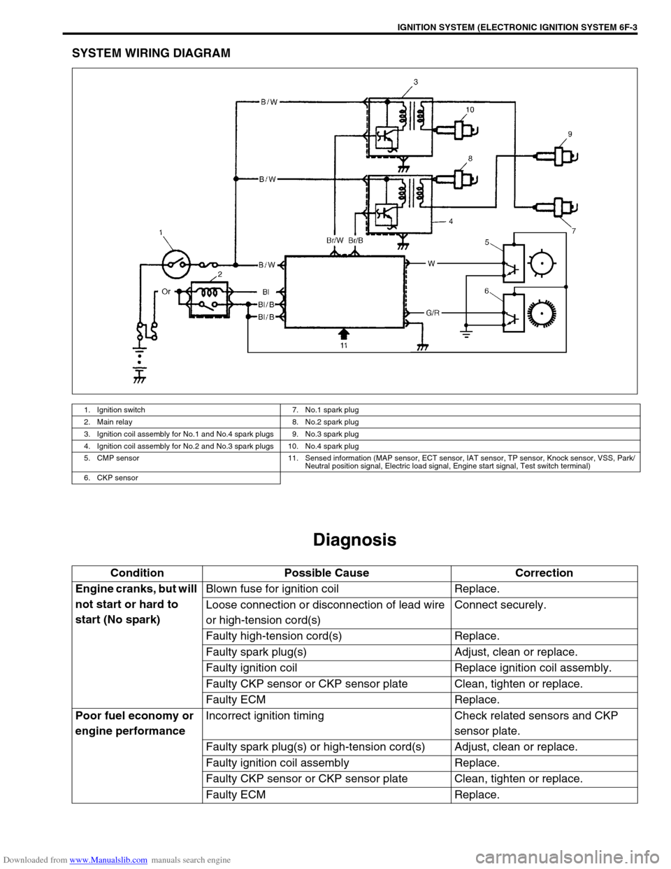
SYSTEM WIRING DIAGRAM
Diagnosis
1. Ignition switch 7. No.1 spark plug
2. Main relay 8. No.2 spark plug
3. Ignition coil assembly for No.1 and No.4 spark plugs 9. No.3 spark plug
4. Ignition coil assembly for No.2 and No.3 spark plugs 10. No.4 spark plug
5. CMP sensor 11. Sensed information (MAP sensor, ECT sensor, IAT sensor, TP sensor, Knock sensor, VSS, Park/
Neutral position signal, Electric load signal, Engine start signal, Test switch terminal)
6. CKP sensor
Condition Possible Cause Correction
Engine cranks, but will
not start or hard to
start (No spark)Blown fuse for ignition coil Replace.
Loose connection or disconnection of lead wire
or high-tension cord(s)Connect securely.
Faulty high-tension cord(s) Replace.
Faulty spark plug(s) Adjust, clean or replace.
Faulty ignition coil Replace ignition coil assembly.
Faulty CKP sensor or CKP sensor plate Clean, tighten or replace.
Faulty ECM Replace.
Poor fuel economy or
engine performanceIncorrect ignition timing Check related sensors and CKP
sensor plate.
Faulty spark plug(s) or high-tension cord(s) Adjust, clean or replace.
Faulty ignition coil assembly Replace.
Faulty CKP sensor or CKP sensor plate Clean, tighten or replace.
Faulty ECM Replace.