ect SUZUKI JIMNY 2005 3.G Service Workshop Manual
[x] Cancel search | Manufacturer: SUZUKI, Model Year: 2005, Model line: JIMNY, Model: SUZUKI JIMNY 2005 3.GPages: 687, PDF Size: 13.38 MB
Page 490 of 687
Downloaded from www.Manualslib.com manuals search engine ENGINE MECHANICAL (M13 ENGINE) 6A1-9
Valve Lash (Clearance)
1) Remove negative cable at battery.
2) Remove cylinder head cover referring to “Cylinder Head
Cover” in this section.
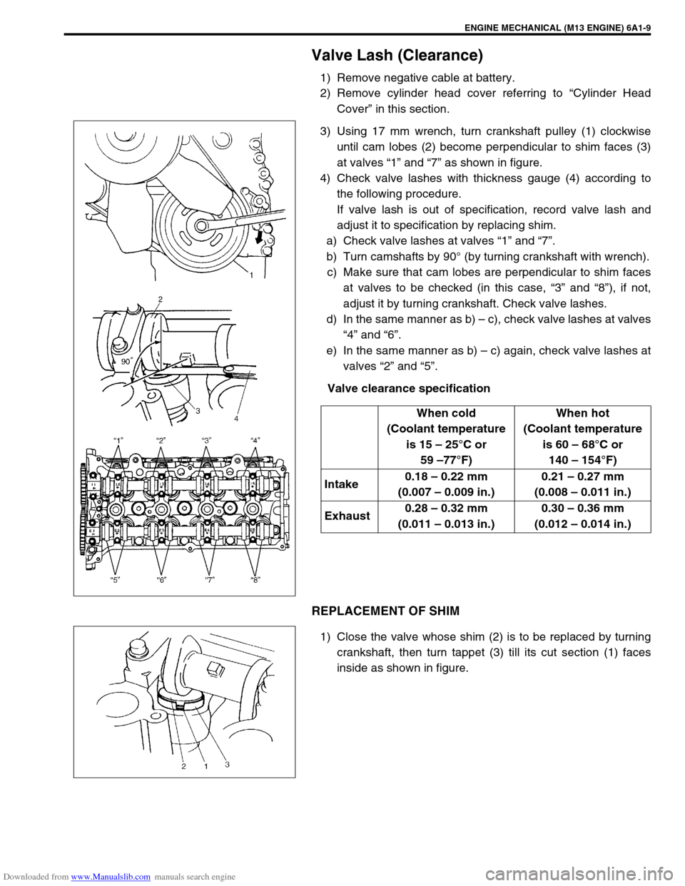
3) Using 17 mm wrench, turn crankshaft pulley (1) clockwise
until cam lobes (2) become perpendicular to shim faces (3)
at valves “1” and “7” as shown in figure.
4) Check valve lashes with thickness gauge (4) according to
the following procedure.
If valve lash is out of specification, record valve lash and
adjust it to specification by replacing shim.
a) Check valve lashes at valves “1” and “7”.
b) Turn camshafts by 90° (by turning crankshaft with wrench).
c) Make sure that cam lobes are perpendicular to shim faces
at valves to be checked (in this case, “3” and “8”), if not,
adjust it by turning crankshaft. Check valve lashes.
d) In the same manner as b) – c), check valve lashes at valves
“4” and “6”.
e) In the same manner as b) – c) again, check valve lashes at
valves “2” and “5”.
Valve clearance specification
REPLACEMENT OF SHIM
1) Close the valve whose shim (2) is to be replaced by turning
crankshaft, then turn tappet (3) till its cut section (1) faces
inside as shown in figure.When cold
(Coolant temperature
is 15 – 25°C or
59 –77°F)When hot
(Coolant temperature
is 60 – 68°C or
140 – 154°F)
Intake0.18 – 0.22 mm
(0.007 – 0.009 in.)0.21 – 0.27 mm
(0.008 – 0.011 in.)
Exhaust0.28 – 0.32 mm
(0.011 – 0.013 in.)0.30 – 0.36 mm
(0.012 – 0.014 in.)
Page 491 of 687
Downloaded from www.Manualslib.com manuals search engine 6A1-10 ENGINE MECHANICAL (M13 ENGINE)
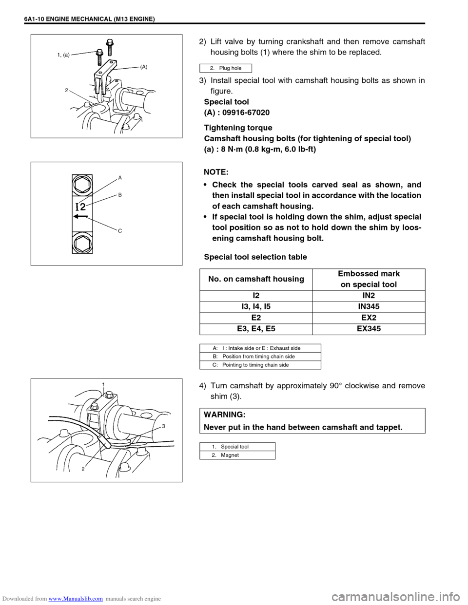
2) Lift valve by turning crankshaft and then remove camshaft
housing bolts (1) where the shim to be replaced.
3) Install special tool with camshaft housing bolts as shown in
figure.
Special tool
(A) : 09916-67020
Tightening torque
Camshaft housing bolts (for tightening of special tool)
(a) : 8 N·m (0.8 kg-m, 6.0 lb-ft)
Special tool selection table
4) Turn camshaft by approximately 90° clockwise and remove
shim (3).
2. Plug hole
NOTE:
Check the special tools carved seal as shown, and
then install special tool in accordance with the location
of each camshaft housing.
If special tool is holding down the shim, adjust special
tool position so as not to hold down the shim by loos-
ening camshaft housing bolt.
No. on camshaft housingEmbossed mark
on special tool
I2 IN2
I3, I4, I5 IN345
E2 EX2
E3, E4, E5 EX345
A: I : Intake side or E : Exhaust side
B: Position from timing chain side
C: Pointing to timing chain side
WARNING:
Never put in the hand between camshaft and tappet.
1. Special tool
2. Magnet
Page 492 of 687
Downloaded from www.Manualslib.com manuals search engine ENGINE MECHANICAL (M13 ENGINE) 6A1-11
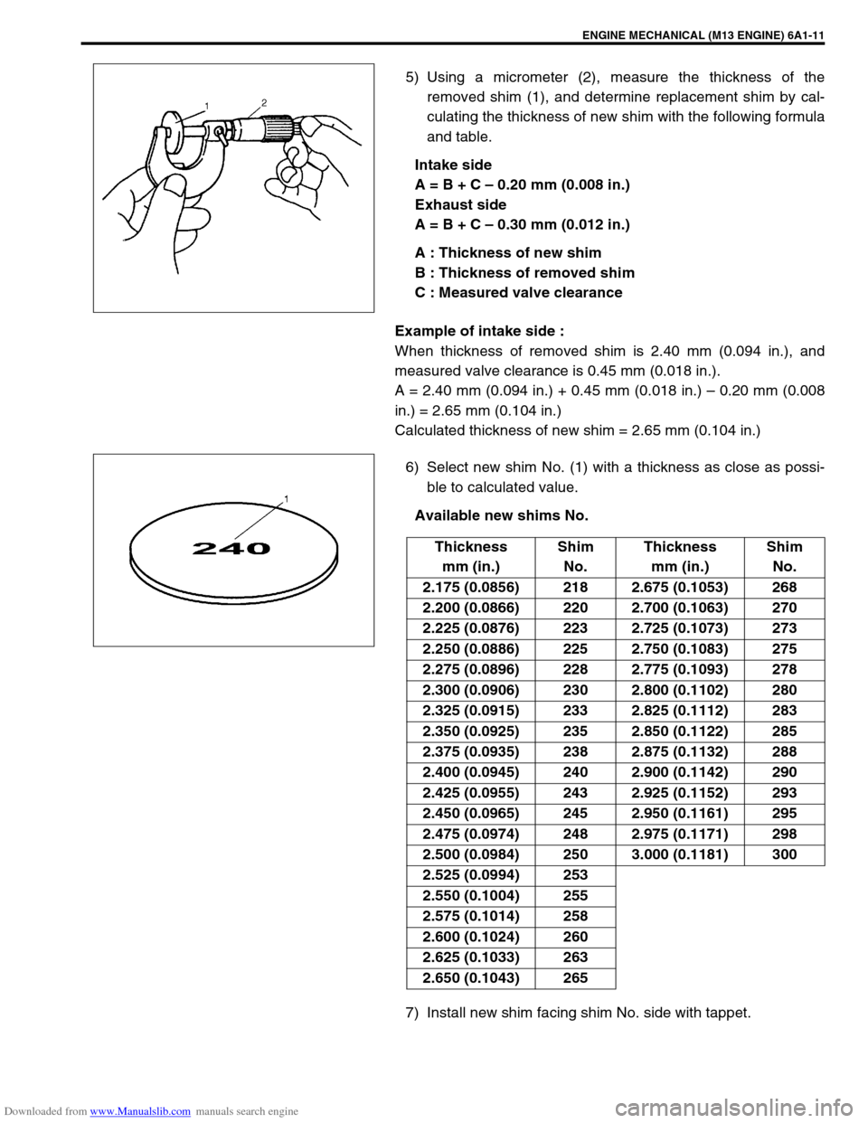
5) Using a micrometer (2), measure the thickness of the
removed shim (1), and determine replacement shim by cal-
culating the thickness of new shim with the following formula
and table.
Intake side
A = B + C – 0.20 mm (0.008 in.)
Exhaust side
A = B + C – 0.30 mm (0.012 in.)
A : Thickness of new shim
B : Thickness of removed shim
C : Measured valve clearance
Example of intake side :
When thickness of removed shim is 2.40 mm (0.094 in.), and
measured valve clearance is 0.45 mm (0.018 in.).
A = 2.40 mm (0.094 in.) + 0.45 mm (0.018 in.) – 0.20 mm (0.008
in.) = 2.65 mm (0.104 in.)
Calculated thickness of new shim = 2.65 mm (0.104 in.)
6) Select new shim No. (1) with a thickness as close as possi-
ble to calculated value.
Available new shims No.
7) Install new shim facing shim No. side with tappet.
Thickness
mm (in.)Shim
No.Thickness
mm (in.)Shim
No.
2.175 (0.0856) 218 2.675 (0.1053) 268
2.200 (0.0866) 220 2.700 (0.1063) 270
2.225 (0.0876) 223 2.725 (0.1073) 273
2.250 (0.0886) 225 2.750 (0.1083) 275
2.275 (0.0896) 228 2.775 (0.1093) 278
2.300 (0.0906) 230 2.800 (0.1102) 280
2.325 (0.0915) 233 2.825 (0.1112) 283
2.350 (0.0925) 235 2.850 (0.1122) 285
2.375 (0.0935) 238 2.875 (0.1132) 288
2.400 (0.0945) 240 2.900 (0.1142) 290
2.425 (0.0955) 243 2.925 (0.1152) 293
2.450 (0.0965) 245 2.950 (0.1161) 295
2.475 (0.0974) 248 2.975 (0.1171) 298
2.500 (0.0984) 250 3.000 (0.1181) 300
2.525 (0.0994) 253
2.550 (0.1004) 255
2.575 (0.1014) 258
2.600 (0.1024) 260
2.625 (0.1033) 263
2.650 (0.1043) 265
Page 493 of 687
Downloaded from www.Manualslib.com manuals search engine 6A1-12 ENGINE MECHANICAL (M13 ENGINE)
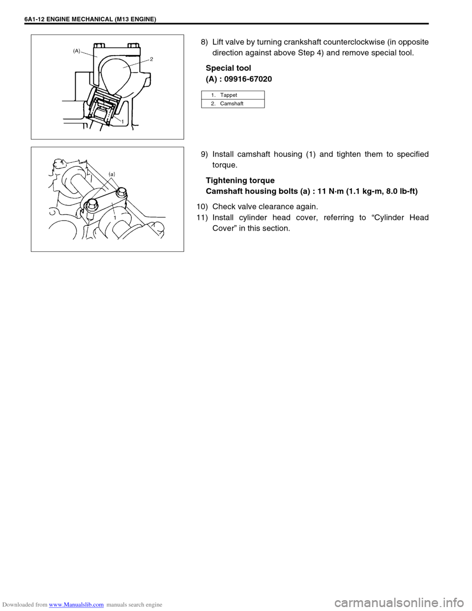
8) Lift valve by turning crankshaft counterclockwise (in opposite
direction against above Step 4) and remove special tool.
Special tool
(A) : 09916-67020
9) Install camshaft housing (1) and tighten them to specified
torque.
Tightening torque
Camshaft housing bolts (a) : 11 N·m (1.1 kg-m, 8.0 lb-ft)
10) Check valve clearance again.
11) Install cylinder head cover, referring to “Cylinder Head
Cover” in this section.
1. Tappet
2. Camshaft
Page 494 of 687
Downloaded from www.Manualslib.com manuals search engine ENGINE MECHANICAL (M13 ENGINE) 6A1-13
On-Vehicle Service
Air Cleaner Element
REMOVAL
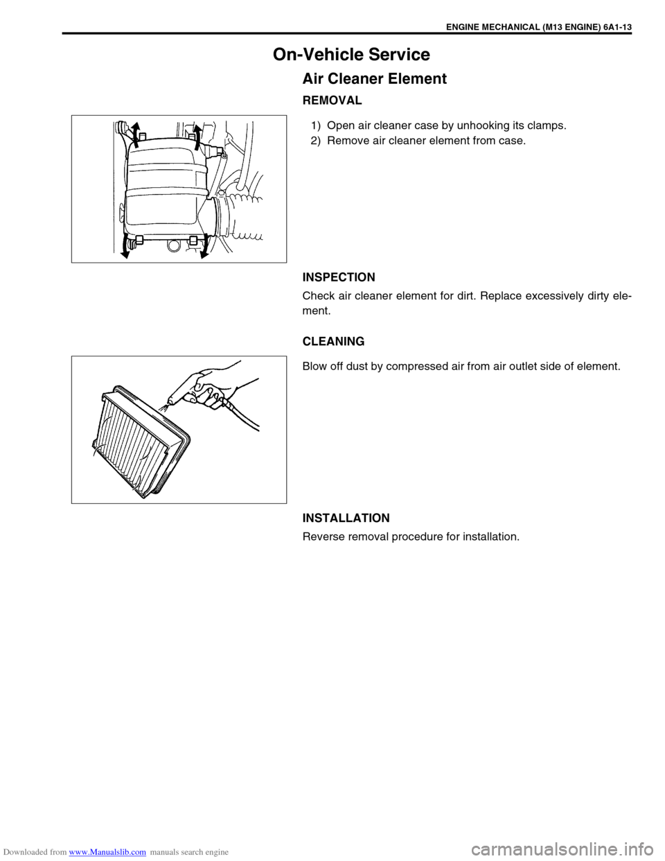
1) Open air cleaner case by unhooking its clamps.
2) Remove air cleaner element from case.
INSPECTION
Check air cleaner element for dirt. Replace excessively dirty ele-
ment.
CLEANING
Blow off dust by compressed air from air outlet side of element.
INSTALLATION
Reverse removal procedure for installation.
Page 495 of 687
Downloaded from www.Manualslib.com manuals search engine 6A1-14 ENGINE MECHANICAL (M13 ENGINE)
Air Cleaner Assembly
REMOVAL
1) Disconnect negative cable at battery.
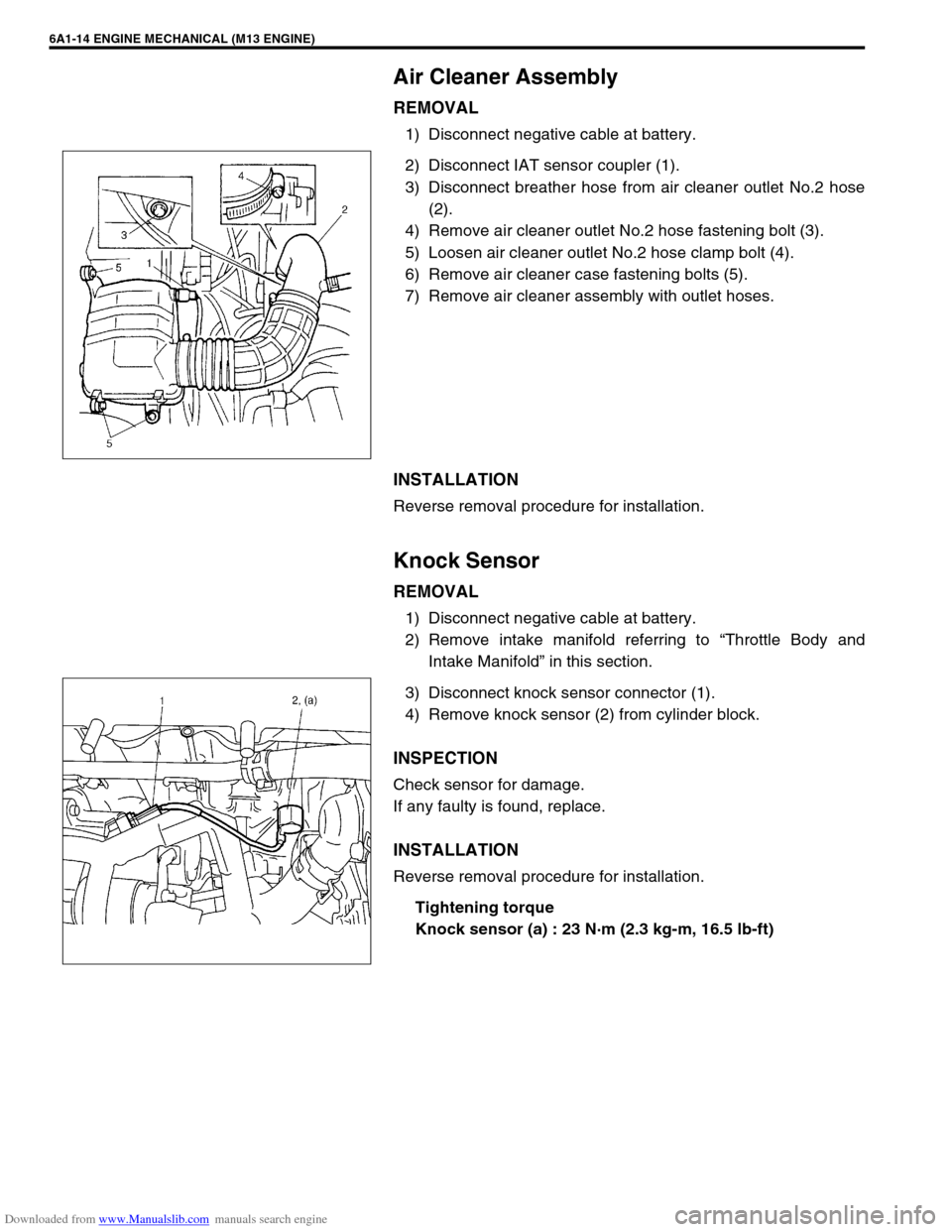
2) Disconnect IAT sensor coupler (1).
3) Disconnect breather hose from air cleaner outlet No.2 hose
(2).
4) Remove air cleaner outlet No.2 hose fastening bolt (3).
5) Loosen air cleaner outlet No.2 hose clamp bolt (4).
6) Remove air cleaner case fastening bolts (5).
7) Remove air cleaner assembly with outlet hoses.
INSTALLATION
Reverse removal procedure for installation.
Knock Sensor
REMOVAL
1) Disconnect negative cable at battery.
2) Remove intake manifold referring to “Throttle Body and
Intake Manifold” in this section.
3) Disconnect knock sensor connector (1).
4) Remove knock sensor (2) from cylinder block.
INSPECTION
Check sensor for damage.
If any faulty is found, replace.
INSTALLATION
Reverse removal procedure for installation.
Tightening torque
Knock sensor (a) : 23 N·m (2.3 kg-m, 16.5 lb-ft)
Page 496 of 687
Downloaded from www.Manualslib.com manuals search engine ENGINE MECHANICAL (M13 ENGINE) 6A1-15
Cylinder Head Cover
REMOVAL
1) Disconnect negative cable at battery.
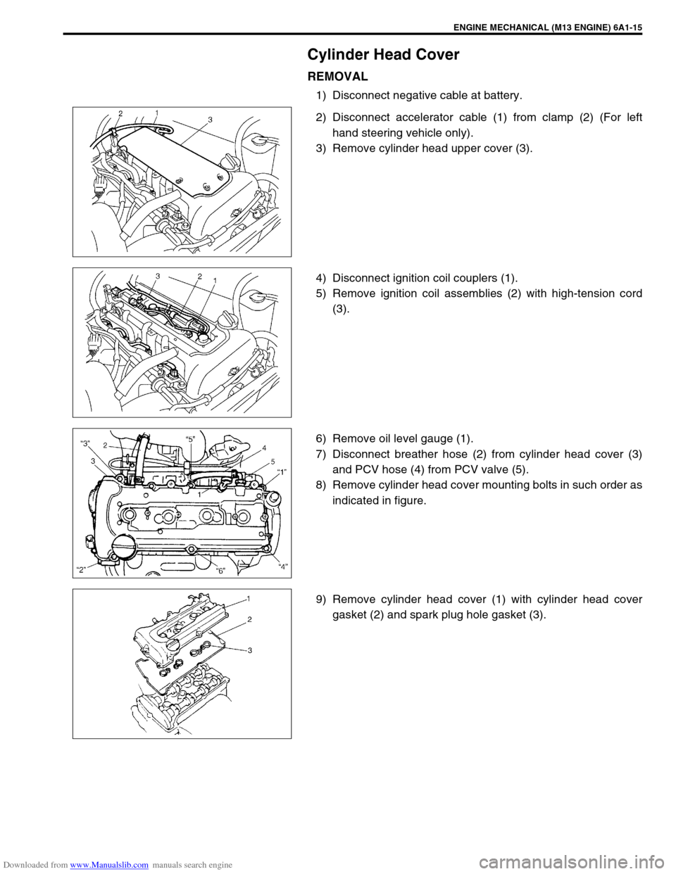
2) Disconnect accelerator cable (1) from clamp (2) (For left
hand steering vehicle only).
3) Remove cylinder head upper cover (3).
4) Disconnect ignition coil couplers (1).
5) Remove ignition coil assemblies (2) with high-tension cord
(3).
6) Remove oil level gauge (1).
7) Disconnect breather hose (2) from cylinder head cover (3)
and PCV hose (4) from PCV valve (5).
8) Remove cylinder head cover mounting bolts in such order as
indicated in figure.
9) Remove cylinder head cover (1) with cylinder head cover
gasket (2) and spark plug hole gasket (3).
Page 497 of 687
Downloaded from www.Manualslib.com manuals search engine 6A1-16 ENGINE MECHANICAL (M13 ENGINE)
INSTALLATION
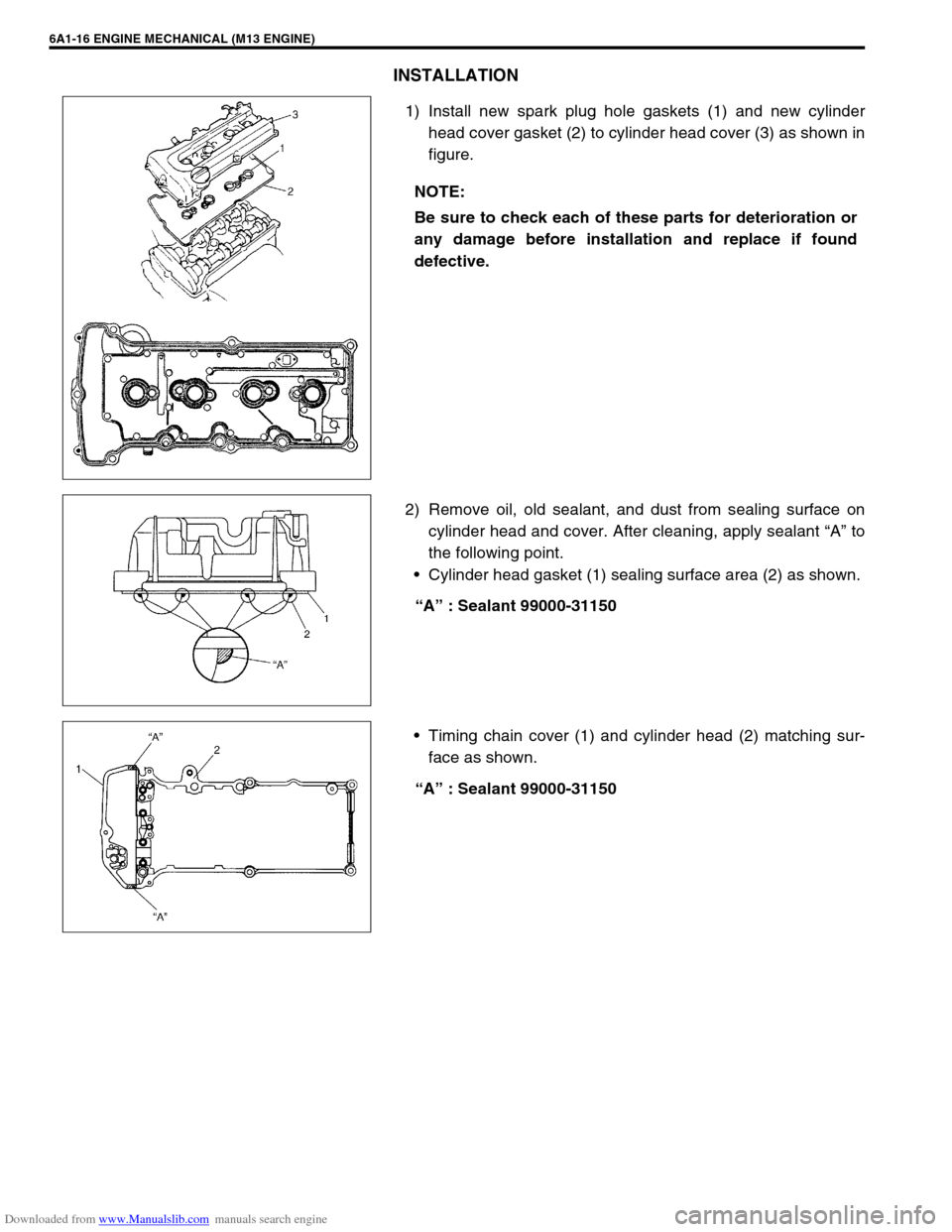
1) Install new spark plug hole gaskets (1) and new cylinder
head cover gasket (2) to cylinder head cover (3) as shown in
figure.
2) Remove oil, old sealant, and dust from sealing surface on
cylinder head and cover. After cleaning, apply sealant “A” to
the following point.
Cylinder head gasket (1) sealing surface area (2) as shown.
“A” : Sealant 99000-31150
Timing chain cover (1) and cylinder head (2) matching sur-
face as shown.
“A” : Sealant 99000-31150 NOTE:
Be sure to check each of these parts for deterioration or
any damage before installation and replace if found
defective.
Page 498 of 687
Downloaded from www.Manualslib.com manuals search engine ENGINE MECHANICAL (M13 ENGINE) 6A1-17
3) Install cylinder head cover to cylinder head.
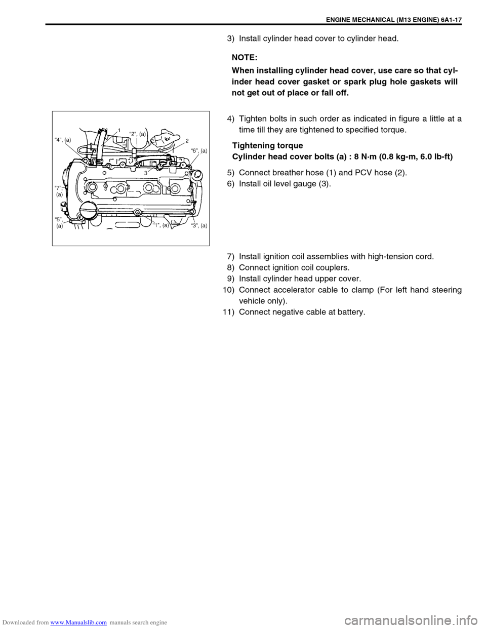
4) Tighten bolts in such order as indicated in figure a little at a
time till they are tightened to specified torque.
Tightening torque
Cylinder head cover bolts (a) : 8 N·m (0.8 kg-m, 6.0 lb-ft)
5) Connect breather hose (1) and PCV hose (2).
6) Install oil level gauge (3).
7) Install ignition coil assemblies with high-tension cord.
8) Connect ignition coil couplers.
9) Install cylinder head upper cover.
10) Connect accelerator cable to clamp (For left hand steering
vehicle only).
11) Connect negative cable at battery.NOTE:
When installing cylinder head cover, use care so that cyl-
inder head cover gasket or spark plug hole gaskets will
not get out of place or fall off.
Page 499 of 687
Downloaded from www.Manualslib.com manuals search engine 6A1-18 ENGINE MECHANICAL (M13 ENGINE)
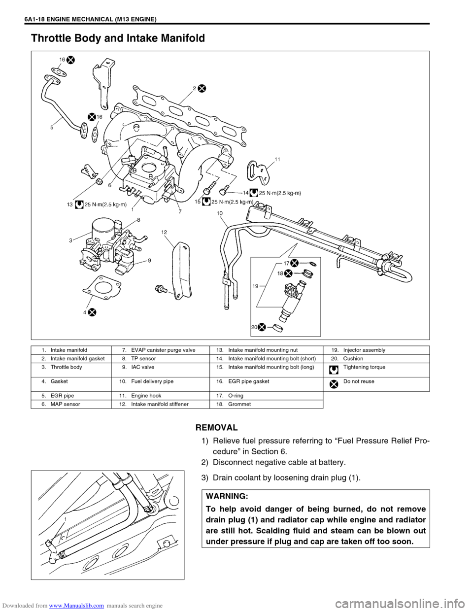
Throttle Body and Intake Manifold
REMOVAL
1) Relieve fuel pressure referring to “Fuel Pressure Relief Pro-
cedure” in Section 6.
2) Disconnect negative cable at battery.
3) Drain coolant by loosening drain plug (1).
1. Intake manifold 7. EVAP canister purge valve 13. Intake manifold mounting nut 19. Injector assembly
2. Intake manifold gasket 8. TP sensor 14. Intake manifold mounting bolt (short) 20. Cushion
3. Throttle body 9. IAC valve 15. Intake manifold mounting bolt (long) Tightening torque
4. Gasket 10. Fuel delivery pipe 16. EGR pipe gasket Do not reuse
5. EGR pipe 11. Engine hook 17. O-ring
6. MAP sensor 12. Intake manifold stiffener 18. Grommet
WARNING:
To help avoid danger of being burned, do not remove
drain plug (1) and radiator cap while engine and radiator
are still hot. Scalding fluid and steam can be blown out
under pressure if plug and cap are taken off too soon.