engine SUZUKI JIMNY 2005 3.G Service Workshop Manual
[x] Cancel search | Manufacturer: SUZUKI, Model Year: 2005, Model line: JIMNY, Model: SUZUKI JIMNY 2005 3.GPages: 687, PDF Size: 13.38 MB
Page 471 of 687

Downloaded from www.Manualslib.com manuals search engine 6-114 ENGINE GENERAL INFORMATION AND DIAGNOSIS
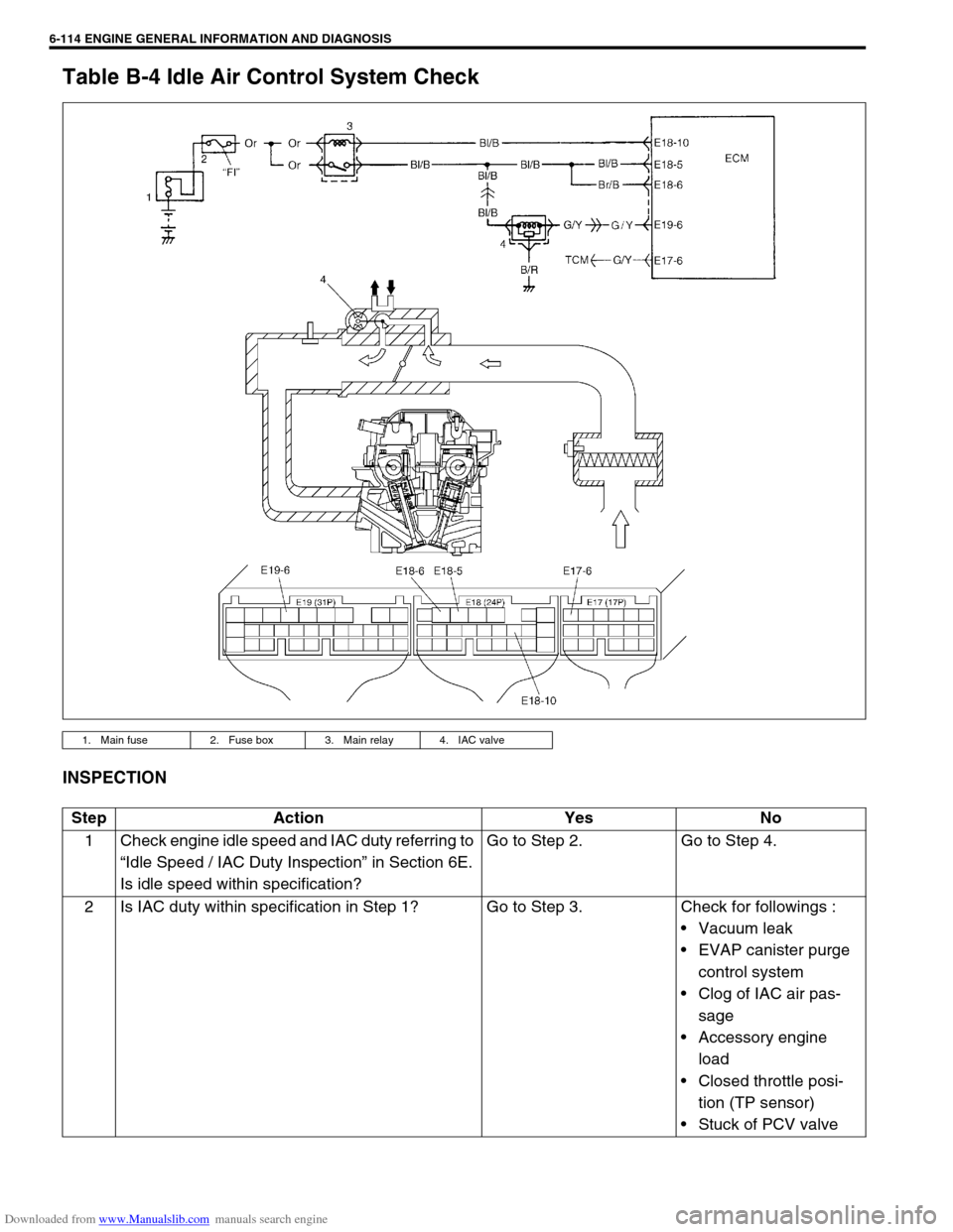
Table B-4 Idle Air Control System Check
INSPECTION
1. Main fuse 2. Fuse box 3. Main relay 4. IAC valve
Step Action Yes No
1 Check engine idle speed and IAC duty referring to
“Idle Speed / IAC Duty Inspection” in Section 6E.
Is idle speed within specification?Go to Step 2. Go to Step 4.
2 Is IAC duty within specification in Step 1? Go to Step 3. Check for followings :
Vacuum leak
EVAP canister purge
control system
Clog of IAC air pas-
sage
Accessory engine
load
Closed throttle posi-
tion (TP sensor)
Stuck of PCV valve
Page 472 of 687

Downloaded from www.Manualslib.com manuals search engine ENGINE GENERAL INFORMATION AND DIAGNOSIS 6-115
3 Is engine idle speed kept specified speed even
with headlight ON?System is in good condi-
tion.Check IAC system for
operation referring to
Step 3 or Step 4 of DTC
P0505 Diag. Flow Table.
4 Was idle speed higher than specification in Step
1?Go to Step 5. Go to Step 8.
5 Check A/C (input) signal circuit referring to Step 1
of Table B-5 A/C Signal Circuit Check, if
equipped. (A/C signal can be also checked by
using SUZUKI scan tool.)
Is it in good condition?Go to Step 6. Repair or replace A/C
signal circuit or A/C sys-
tem.
6 Check IAC system referring to Step 2 to Step 4 of
DTC P0505 Diag. Flow Table.
Is check result satisfactory?Go to Step 7. Go to Step 5 of DTC
P0505 Diag. Flow Table.
7 Was IAC duty less than about 3% (or more than
about 97% for OFF duty meter) in Step 1 of this
table?Check abnormal air
inhaling from air intake
system, PCV valve and
EVAP canister purge
control system.Check TP sensor
(closed throttle position)
and ECT sensor for per-
formance.
If sensors are OK, sub-
stitute a known-good
ECM.
8 Is SUZUKI scan tool available? Go to Step 9. Go to Step 10.
9 Check PNP signal (“D” range signal).
1) Connect SUZUKI scan tool to DLC with igni-
tion switch OFF.
2) Turn ignition switch ON and check PNP signal
(“P/N” and “D” range) on display when shifting
selector lever to each range. See Table 1.
Is check result satisfactory?Go to Step 11. Repair or replace.
10 Check PNP signal (“D” range signal).
1) Turn ignition switch ON.
2) Check voltage at terminal E17-6 of ECM con-
nector connected. See Fig. 1 and Table 1.
Is check result satisfactory?Go to Step 11. Repair or replace.
11 Check IAC system referring to Step 2 to Step 4 of
DTC P0505 Diag. Flow Table.
Is check result satisfactory?Go to Step 12. Go to Step 5 of DTC
P0505 Diag. Flow Table.
12 Was IAC duty more than about 30% or ✱40% (or
less than 70% or ✱60% for OFF duty meter) in
Step 1 of this table? See NOTE.Check parts or system
which can cause engine
low idle.
Accessory engine load
Clog of air passage
Etc.Substitute a known-good
ECM and recheck. Step Action Yes No
NOTE:
Duty value with (
✱
✱✱ ✱) are applicable to vehicle used at high altitude (higher than 2000 m or 6560 ft).
Page 473 of 687

Downloaded from www.Manualslib.com manuals search engine 6-116 ENGINE GENERAL INFORMATION AND DIAGNOSIS
Fig. 1 for Step 10
Table 1 for Step 9 and 10
Scan tool or voltmeter
SUZUKI SCAN TOOL
DISPLAYVOLTAGE AT E17-6
Selector lever
position“P” and “N” range P/N range 10 – 14V
“R”, “D”, “2” and “L” range D range 0 – 1V
Page 474 of 687

Downloaded from www.Manualslib.com manuals search engine ENGINE GENERAL INFORMATION AND DIAGNOSIS 6-117
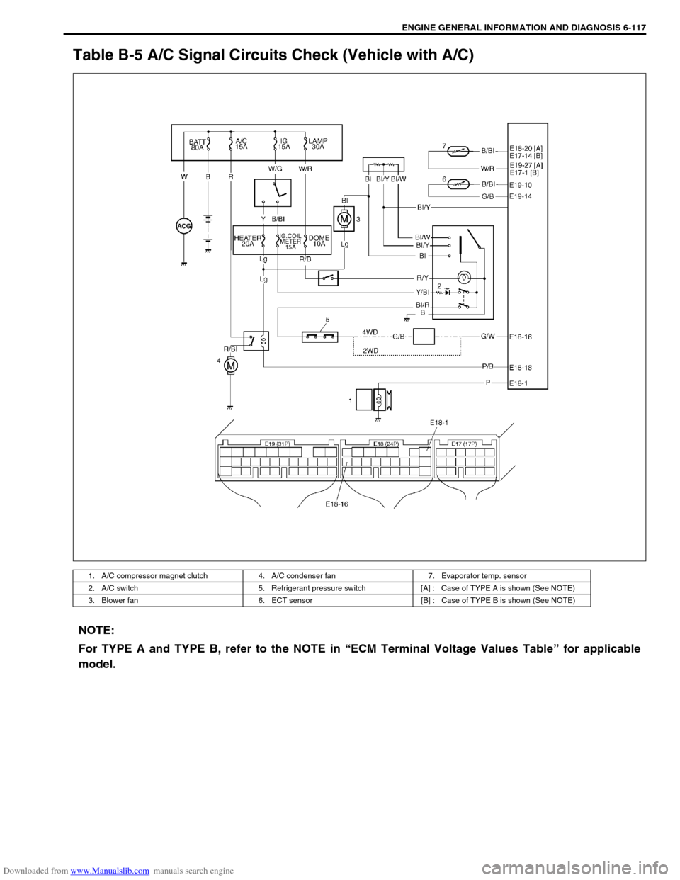
Table B-5 A/C Signal Circuits Check (Vehicle with A/C)
1. A/C compressor magnet clutch 4. A/C condenser fan 7. Evaporator temp. sensor
2. A/C switch 5. Refrigerant pressure switch [A] : Case of TYPE A is shown (See NOTE)
3. Blower fan 6. ECT sensor [B] : Case of TYPE B is shown (See NOTE)
NOTE:
For TYPE A and TYPE B, refer to the NOTE in “ECM Terminal Voltage Values Table” for applicable
model.
Page 475 of 687

Downloaded from www.Manualslib.com manuals search engine 6-118 ENGINE GENERAL INFORMATION AND DIAGNOSIS
INSPECTION
Fig. 1 for Step 1Step Action Yes No
1 Check evaporator temp. sensor.
1) Disconnect ECM connectors with ignition
switch at OFF position.
2) Check resistance between E19-14 terminal
and E19-10 terminal.
Reference value
(Refer to characteristic curve below)
ECT sensor resistance
At 0°C 6.3 – 6.9 k
Ω
ΩΩ Ω
At 25°C 1.8 – 2.2 k
Ω
ΩΩ Ω
Is it within specification?Go to Step 2. Faulty A/C evaporator
thermistor or its circuit.
2 Check A/C switch circuit.
1) Check voltage at E18-16 terminal under
each condition given below.
A/C switch signal specification
Ignition switch ON A/C switch OFF
: 10 – 14 V
Ignition switch ON A/C switch ON
: 0 – 1 V
Is check result satisfactory?Go to Step 3.“G/W” wire open or short
Poor E18-16 terminal con-
nection
If wire and connection are
OK, substitute a known-
good ECM and recheck.
Go to Step 3.
3 Check A/C compressor signal.
1) Check voltage at E18-1 terminal under each
condition given below. See NOTE.
A/C compressor signal specification
While engine running, A/C switch OFF
: 0 V
While engine running, A/C switch ON
: 10 – 14 V
Is check result satisfactory?A/C control system cir-
cuits are in good condi-
tion.“P” wire open or short
Poor E18-1 terminal con-
nection
If wire and connection are
OK, substitute a known-
good ECM and recheck.
NOTE:
When A/C evaporator thermistor temp. is below 2.5 °C (36.5 °F), A/C remain OFF (E18-1 terminal volt-
age become 0 – 1 V). This condition is not abnormal.
Page 476 of 687

Downloaded from www.Manualslib.com manuals search engine ENGINE GENERAL INFORMATION AND DIAGNOSIS 6-119
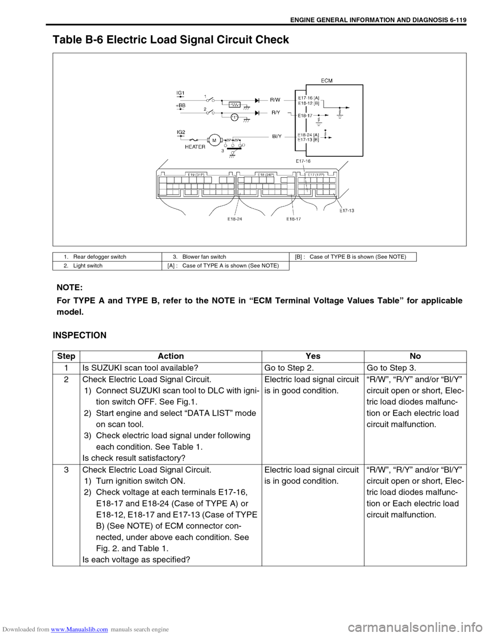
Table B-6 Electric Load Signal Circuit Check
INSPECTION
1. Rear defogger switch 3. Blower fan switch [B] : Case of TYPE B is shown (See NOTE)
2. Light switch [A] : Case of TYPE A is shown (See NOTE)
NOTE:
For TYPE A and TYPE B, refer to the NOTE in “ECM Terminal Voltage Values Table” for applicable
model.
Step Action Yes No
1 Is SUZUKI scan tool available? Go to Step 2. Go to Step 3.
2 Check Electric Load Signal Circuit.
1) Connect SUZUKI scan tool to DLC with igni-
tion switch OFF. See Fig.1.
2) Start engine and select “DATA LIST” mode
on scan tool.
3) Check electric load signal under following
each condition. See Table 1.
Is check result satisfactory?Electric load signal circuit
is in good condition.“R/W”, “R/Y” and/or “Bl/Y”
circuit open or short, Elec-
tric load diodes malfunc-
tion or Each electric load
circuit malfunction.
3 Check Electric Load Signal Circuit.
1) Turn ignition switch ON.
2) Check voltage at each terminals E17-16,
E18-17 and E18-24 (Case of TYPE A) or
E18-12, E18-17 and E17-13 (Case of TYPE
B) (See NOTE) of ECM connector con-
nected, under above each condition. See
Fig. 2. and Table 1.
Is each voltage as specified?Electric load signal circuit
is in good condition.“R/W”, “R/Y” and/or “Bl/Y”
circuit open or short, Elec-
tric load diodes malfunc-
tion or Each electric load
circuit malfunction.
Page 477 of 687
![SUZUKI JIMNY 2005 3.G Service Workshop Manual Downloaded from www.Manualslib.com manuals search engine 6-120 ENGINE GENERAL INFORMATION AND DIAGNOSIS
[A] Fig. 1 for Step 2 / [B] Fig. 2 for Step 3
Table 1 for Step 2 and 3
Scan tool or voltmeter
SU SUZUKI JIMNY 2005 3.G Service Workshop Manual Downloaded from www.Manualslib.com manuals search engine 6-120 ENGINE GENERAL INFORMATION AND DIAGNOSIS
[A] Fig. 1 for Step 2 / [B] Fig. 2 for Step 3
Table 1 for Step 2 and 3
Scan tool or voltmeter
SU](/img/20/7588/w960_7588-476.png)
Downloaded from www.Manualslib.com manuals search engine 6-120 ENGINE GENERAL INFORMATION AND DIAGNOSIS
[A] Fig. 1 for Step 2 / [B] Fig. 2 for Step 3
Table 1 for Step 2 and 3
Scan tool or voltmeter
SUZUKI
SCAN TOOLVOLTAGE
AT E18-17,
E17-16 or
E18-12VOLTAGE
AT E18-24 or
E17-13
Ignition switch ON, Small
light, heater blower fan and
rear defogger all turnedOFF OFF 0V 10 – 14V
ON ON 10 – 14V 0V
Page 478 of 687

Downloaded from www.Manualslib.com manuals search engine ENGINE GENERAL INFORMATION AND DIAGNOSIS 6-121
TAble B-7 A/C Condenser Fan Control System Check
INSPECTION
Step Action Yes No
1 Check Fan Control System.
1) Connect scan tool to DLC with ignition switch OFF. See
Fig. 1.
2) Start engine and select “DATA LIST” mode on scan tool.
3) Warm up engine until coolant temp. is 110 °C, 230 °F or
higher and A/C switch turn OFF. (If engine coolant temp.
does not rise, check engine cooling system or ECT sen-
sor.)
Is A/C condenser fan started when engine coolant temp.
reached above temp.?A/C condenser fan con-
trol system is in good
condition.Go to Step 2.
2 Check A/C Condenser Fan Relay and Its Circuit.
1) Check DTC and pending DTC with scan tool.
Is DTC P0481 displayed?Go to DTC P0481 Diag.
Flow Table.Go to Step 3.
3 Check A/C Condenser Fan Relay (1).
1) Turn ignition switch OFF and remove A/C condenser fan
relay.
2) Check for proper connection to relay at terminals “A”
and “B”.
3) If OK, check that there is continuity between “A” and “B”
when battery is connected to terminals “C” and “D”. See
Fig. 2.
Is check result satisfactory?Go to Step 4. Replace A/C
condenser fan
relay.
Page 479 of 687
![SUZUKI JIMNY 2005 3.G Service Workshop Manual Downloaded from www.Manualslib.com manuals search engine 6-122 ENGINE GENERAL INFORMATION AND DIAGNOSIS
[A] Fig. 1 for Step 1 / [B] Fig. 2 for Step 3
Fig. 3 for Step 44 Check A/C Condenser Fan (1).
1) SUZUKI JIMNY 2005 3.G Service Workshop Manual Downloaded from www.Manualslib.com manuals search engine 6-122 ENGINE GENERAL INFORMATION AND DIAGNOSIS
[A] Fig. 1 for Step 1 / [B] Fig. 2 for Step 3
Fig. 3 for Step 44 Check A/C Condenser Fan (1).
1)](/img/20/7588/w960_7588-478.png)
Downloaded from www.Manualslib.com manuals search engine 6-122 ENGINE GENERAL INFORMATION AND DIAGNOSIS
[A] Fig. 1 for Step 1 / [B] Fig. 2 for Step 3
Fig. 3 for Step 44 Check A/C Condenser Fan (1).
1) Turn ignition switch OFF.
2) Disconnect fan motor connector (2).
3) Check for proper connection to motor at “R/Bl” and “B”
terminals.
4) If OK, connect battery to motor and check for operation.
See Fig. 3.
Is it in good condition?“R”, “R/Bl” or “B” circuit
open.Replace A/C
condenser fan
motor. Step Action Yes No
Page 480 of 687

Downloaded from www.Manualslib.com manuals search engine ENGINE GENERAL INFORMATION AND DIAGNOSIS 6-123
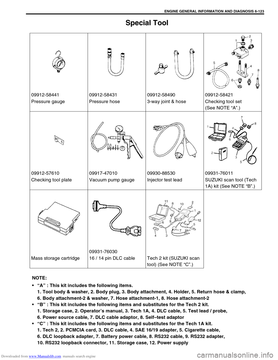
Special Tool
09912-58441 09912-58431 09912-58490 09912-58421
Pressure gauge Pressure hose 3-way joint & hose Checking tool set
(See NOTE “A”.)
09912-57610 09917-47010 09930-88530 09931-76011
Checking tool plate Vacuum pump gauge Injector test lead SUZUKI scan tool (Tech
1A) kit (See NOTE “B”.)
09931-76030
Mass storage cartridge 16 / 14 pin DLC cable Tech 2 kit (SUZUKI scan
tool) (See NOTE “C”.)
NOTE:
“A” : This kit includes the following items.
1. Tool body & washer, 2. Body plug, 3. Body attachment, 4. Holder, 5. Return hose & clamp,
6. Body attachment-2 & washer, 7. Hose attachment-1, 8. Hose attachment-2
“B” : This kit includes the following items and substitutes for the Tech 2 kit.
1. Storage case, 2. Operator’s manual, 3. Tech 1A, 4. DLC cable, 5. Test lead / probe,
6. Power source cable, 7. DLC cable adaptor, 8. Self–test adaptor
“C” : This kit includes the following items and substitutes for the Tech 1A kit.
1. Tech 2, 2. PCMCIA card, 3. DLC cable, 4. SAE 16/19 adapter, 5. Cigarette cable,
6. DLC loopback adapter, 7. Battery power cable, 8. RS232 cable, 9. RS232 adapter,
10. RS232 loopback connector, 11. Storage case, 12. Power supply