BOX SUZUKI JIMNY 2005 3.G Service Service Manual
[x] Cancel search | Manufacturer: SUZUKI, Model Year: 2005, Model line: JIMNY, Model: SUZUKI JIMNY 2005 3.GPages: 687, PDF Size: 13.38 MB
Page 356 of 687
Downloaded from www.Manualslib.com manuals search engine ANTILOCK BRAKE SYSTEM (ABS) 5E-39
G Sensor
REMOVAL
1) Turn ignition switch “OFF” and disconnect battery negative
cable.
2) Remove rear center console box.
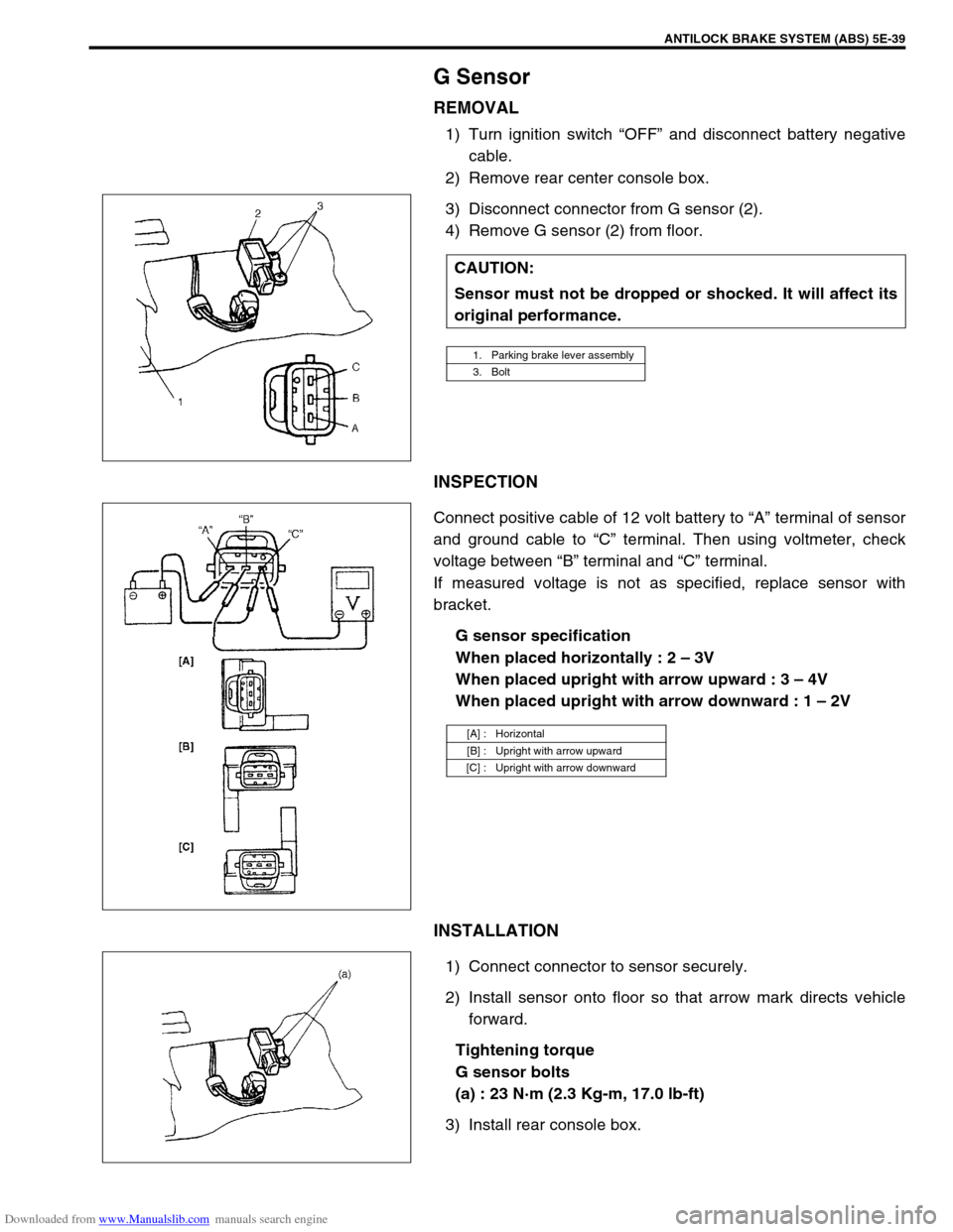
3) Disconnect connector from G sensor (2).
4) Remove G sensor (2) from floor.
INSPECTION
Connect positive cable of 12 volt battery to “A” terminal of sensor
and ground cable to “C” terminal. Then using voltmeter, check
voltage between “B” terminal and “C” terminal.
If measured voltage is not as specified, replace sensor with
bracket.
G sensor specification
When placed horizontally : 2 – 3V
When placed upright with arrow upward : 3 – 4V
When placed upright with arrow downward : 1 – 2V
INSTALLATION
1) Connect connector to sensor securely.
2) Install sensor onto floor so that arrow mark directs vehicle
forward.
Tightening torque
G sensor bolts
(a) : 23 N·m (2.3 Kg-m, 17.0 lb-ft)
3) Install rear console box.CAUTION:
Sensor must not be dropped or shocked. It will affect its
original performance.
1. Parking brake lever assembly
3. Bolt
[A] : Horizontal
[B] : Upright with arrow upward
[C] : Upright with arrow downward
Page 362 of 687
Downloaded from www.Manualslib.com manuals search engine ENGINE GENERAL INFORMATION AND DIAGNOSIS 6-5
Fuel pressure relief procedure
After making sure that engine is cold, release fuel pressure as fol-
lows.
1) Place transmission gear shift lever in “Neutral” (Shift selector
lever to “P” range for A/T model), set parking brake, and
block drive wheels.
2) Remove relay box cover.
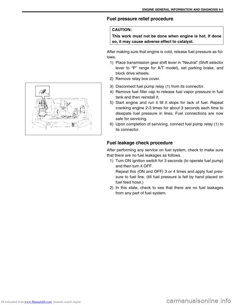
3) Disconnect fuel pump relay (1) from its connector.
4) Remove fuel filler cap to release fuel vapor pressure in fuel
tank and then reinstall it.
5) Start engine and run it till it stops for lack of fuel. Repeat
cranking engine 2-3 times for about 3 seconds each time to
dissipate fuel pressure in lines. Fuel connections are now
safe for servicing.
6) Upon completion of servicing, connect fuel pump relay (1) to
its connector.
Fuel leakage check procedure
After performing any service on fuel system, check to make sure
that there are no fuel leakages as follows.
1) Turn ON ignition switch for 3 seconds (to operate fuel pump)
and then turn it OFF.
Repeat this (ON and OFF) 3 or 4 times and apply fuel pres-
sure to fuel line. (till fuel pressure is felt by hand placed on
fuel feed hose.)
2) In this state, check to see that there are no fuel leakages
from any part of fuel system. CAUTION:
This work must not be done when engine is hot. If done
so, it may cause adverse effect to catalyst.
Page 400 of 687
Downloaded from www.Manualslib.com manuals search engine ENGINE GENERAL INFORMATION AND DIAGNOSIS 6-43
Table A-1 Malfunction Indicator Lamp Circuit Check - Lamp Does Not Come
“ON” at Ignition Switch ON (But Engine at Stop)
CIRCUIT DESCRIPTION
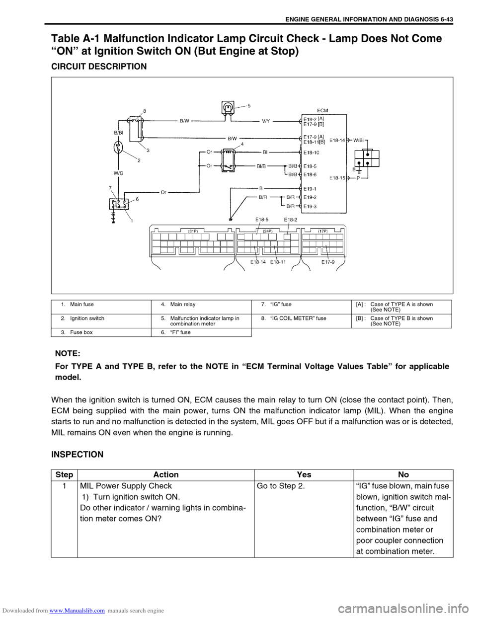
When the ignition switch is turned ON, ECM causes the main relay to turn ON (close the contact point). Then,
ECM being supplied with the main power, turns ON the malfunction indicator lamp (MIL). When the engine
starts to run and no malfunction is detected in the system, MIL goes OFF but if a malfunction was or is detected,
MIL remains ON even when the engine is running.
INSPECTION
1. Main fuse 4. Main relay 7.“IG” fuse [A] : Case of TYPE A is shown
(See NOTE)
2. Ignition switch 5. Malfunction indicator lamp in
combination meter8.“IG COIL METER” fuse [B] : Case of TYPE B is shown
(See NOTE)
3. Fuse box 6.“FI” fuse
NOTE:
For TYPE A and TYPE B, refer to the NOTE in “ECM Terminal Voltage Values Table” for applicable
model.
Step Action Yes No
1 MIL Power Supply Check
1) Turn ignition switch ON.
Do other indicator / warning lights in combina-
tion meter comes ON?Go to Step 2.“IG” fuse blown, main fuse
blown, ignition switch mal-
function, “B/W” circuit
between “IG” fuse and
combination meter or
poor coupler connection
at combination meter.
Page 403 of 687
Downloaded from www.Manualslib.com manuals search engine 6-46 ENGINE GENERAL INFORMATION AND DIAGNOSIS
Table A-5 ECM Power and Ground Circuit Check - MIL Doesn’t Light at Ignition
Switch ON and Engine Doesn’t Start Though It Is Cranked Up
CIRCUIT DESCRIPTION
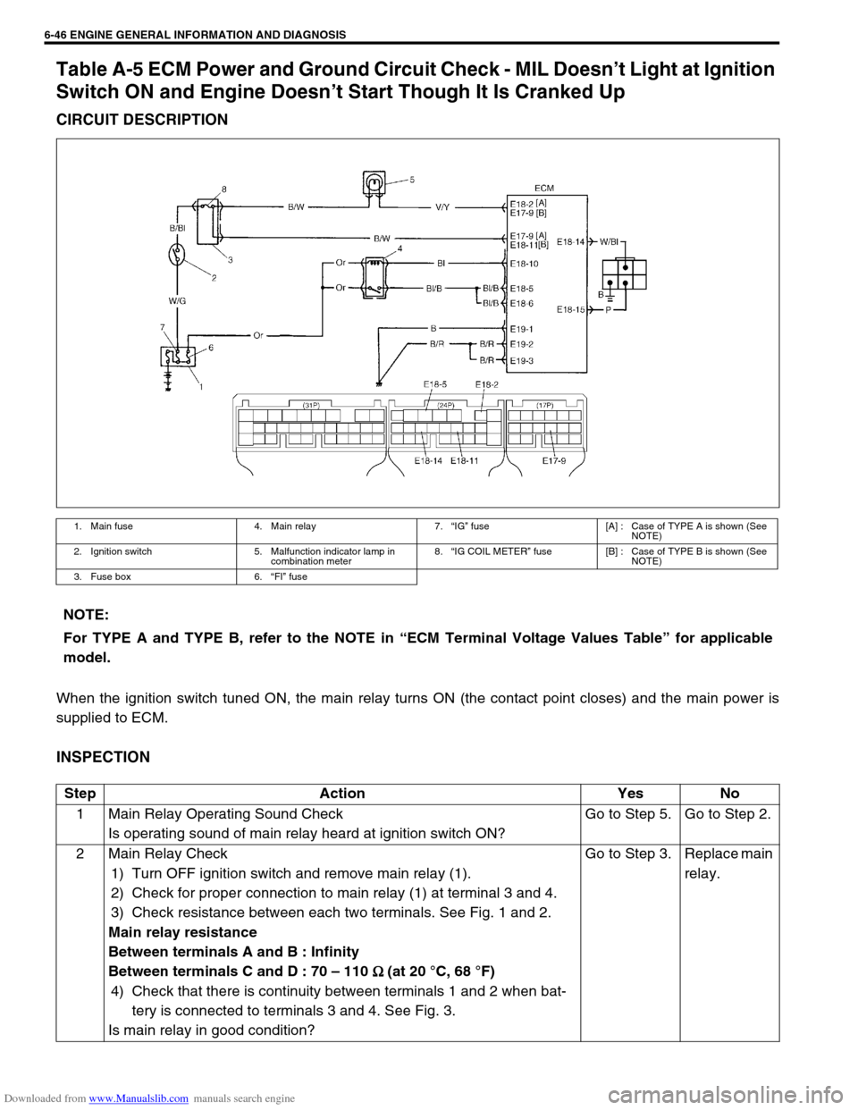
When the ignition switch tuned ON, the main relay turns ON (the contact point closes) and the main power is
supplied to ECM.
INSPECTION
1. Main fuse 4. Main relay 7.“IG” fuse [A] : Case of TYPE A is shown (See
NOTE)
2. Ignition switch 5. Malfunction indicator lamp in
combination meter8.“IG COIL METER” fuse [B] : Case of TYPE B is shown (See
NOTE)
3. Fuse box 6.“FI” fuse
NOTE:
For TYPE A and TYPE B, refer to the NOTE in “ECM Terminal Voltage Values Table” for applicable
model.
Step Action Yes No
1 Main Relay Operating Sound Check
Is operating sound of main relay heard at ignition switch ON?Go to Step 5. Go to Step 2.
2 Main Relay Check
1) Turn OFF ignition switch and remove main relay (1).
2) Check for proper connection to main relay (1) at terminal 3 and 4.
3) Check resistance between each two terminals. See Fig. 1 and 2.
Main relay resistance
Between terminals A and B : Infinity
Between terminals C and D : 70 – 110
Ω
Ω Ω Ω (at 20 °C, 68 °F)
4) Check that there is continuity between terminals 1 and 2 when bat-
tery is connected to terminals 3 and 4. See Fig. 3.
Is main relay in good condition?Go to Step 3. Replace main
relay.
Page 449 of 687
Downloaded from www.Manualslib.com manuals search engine 6-92 ENGINE GENERAL INFORMATION AND DIAGNOSIS
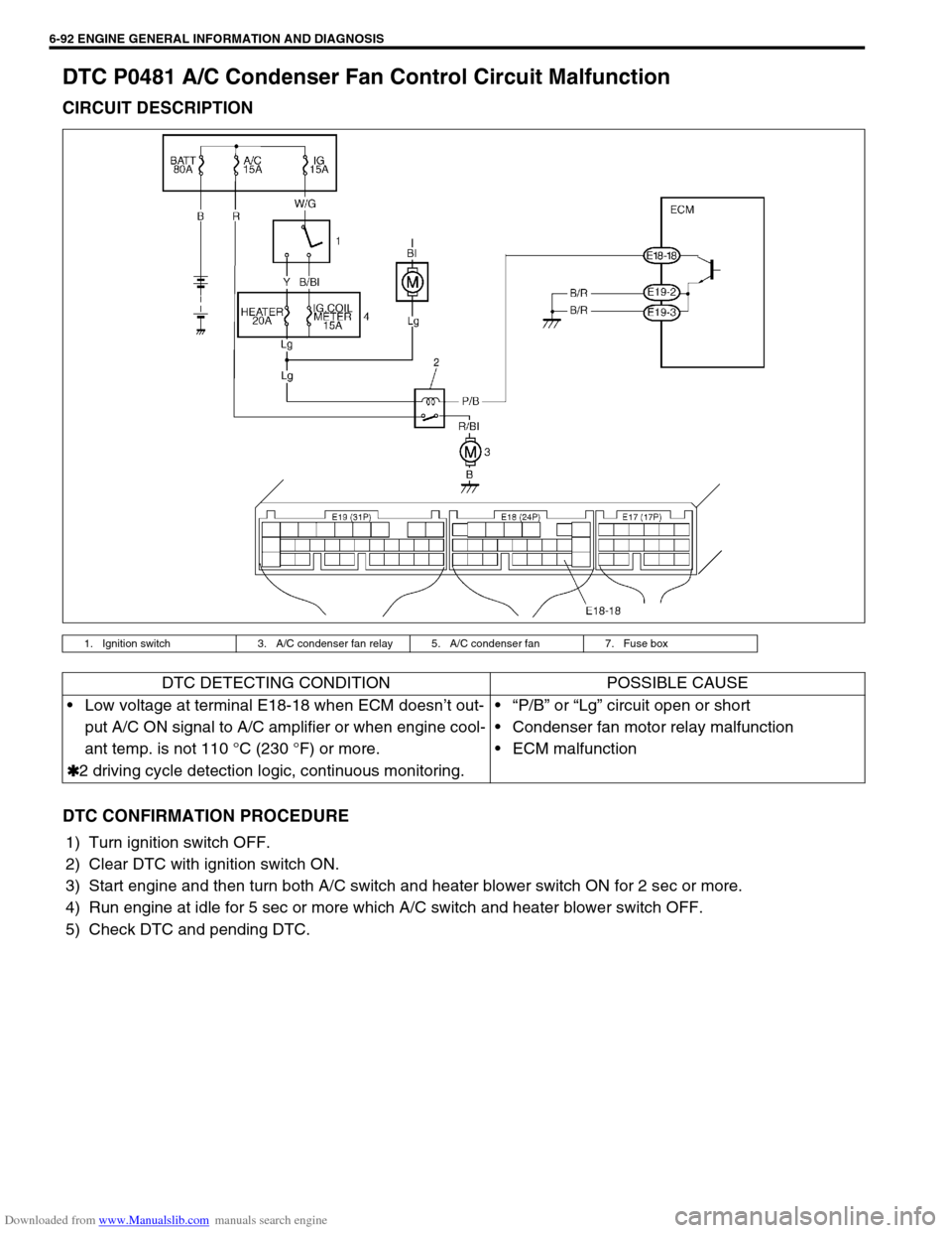
DTC P0481 A/C Condenser Fan Control Circuit Malfunction
CIRCUIT DESCRIPTION
DTC CONFIRMATION PROCEDURE
1) Turn ignition switch OFF.
2) Clear DTC with ignition switch ON.
3) Start engine and then turn both A/C switch and heater blower switch ON for 2 sec or more.
4) Run engine at idle for 5 sec or more which A/C switch and heater blower switch OFF.
5) Check DTC and pending DTC.
1. Ignition switch 3. A/C condenser fan relay 5. A/C condenser fan 7. Fuse box
DTC DETECTING CONDITION POSSIBLE CAUSE
Low voltage at terminal E18-18 when ECM doesn’t out-
put A/C ON signal to A/C amplifier or when engine cool-
ant temp. is not 110 °C (230 °F) or more.
✱
✱✱ ✱2 driving cycle detection logic, continuous monitoring.“P/B” or “Lg” circuit open or short
Condenser fan motor relay malfunction
ECM malfunction
Page 460 of 687
Downloaded from www.Manualslib.com manuals search engine ENGINE GENERAL INFORMATION AND DIAGNOSIS 6-103
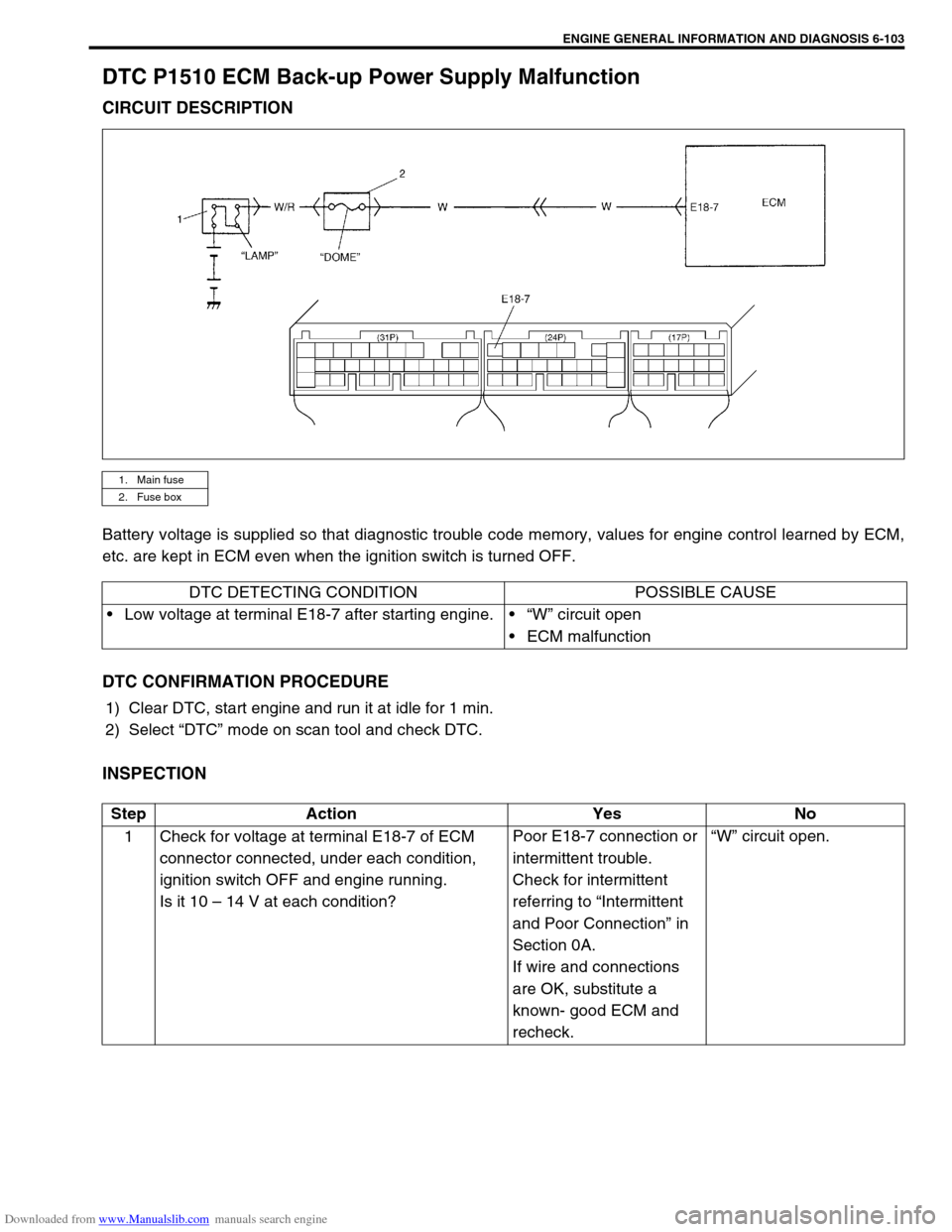
DTC P1510 ECM Back-up Power Supply Malfunction
CIRCUIT DESCRIPTION
Battery voltage is supplied so that diagnostic trouble code memory, values for engine control learned by ECM,
etc. are kept in ECM even when the ignition switch is turned OFF.
DTC CONFIRMATION PROCEDURE
1) Clear DTC, start engine and run it at idle for 1 min.
2) Select “DTC” mode on scan tool and check DTC.
INSPECTION
1. Main fuse
2. Fuse box
DTC DETECTING CONDITION POSSIBLE CAUSE
Low voltage at terminal E18-7 after starting engine.“W” circuit open
ECM malfunction
Step Action Yes No
1 Check for voltage at terminal E18-7 of ECM
connector connected, under each condition,
ignition switch OFF and engine running.
Is it 10 – 14 V at each condition?Poor E18-7 connection or
intermittent trouble.
Check for intermittent
referring to “Intermittent
and Poor Connection” in
Section 0A.
If wire and connections
are OK, substitute a
known- good ECM and
recheck.“W” circuit open.
Page 467 of 687
Downloaded from www.Manualslib.com manuals search engine 6-110 ENGINE GENERAL INFORMATION AND DIAGNOSIS
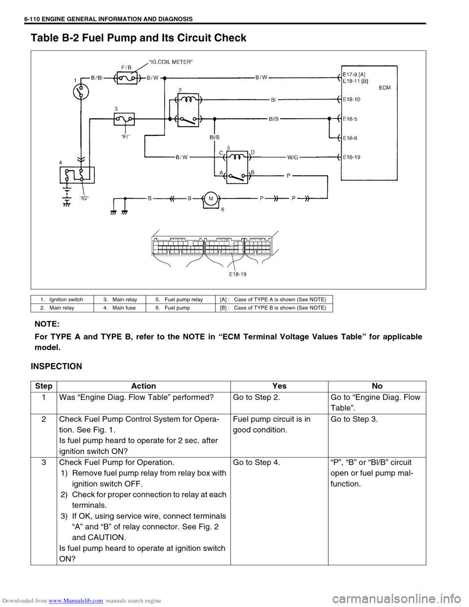
Table B-2 Fuel Pump and Its Circuit Check
INSPECTION
1. Ignition switch 3. Main relay 5. Fuel pump relay [A] : Case of TYPE A is shown (See NOTE)
2. Main relay 4. Main fuse 6. Fuel pump [B] : Case of TYPE B is shown (See NOTE)
NOTE:
For TYPE A and TYPE B, refer to the NOTE in “ECM Terminal Voltage Values Table” for applicable
model.
Step Action Yes No
1Was “Engine Diag. Flow Table” performed? Go to Step 2. Go to “Engine Diag. Flow
Table”.
2 Check Fuel Pump Control System for Opera-
tion. See Fig. 1.
Is fuel pump heard to operate for 2 sec. after
ignition switch ON?Fuel pump circuit is in
good condition.Go to Step 3.
3 Check Fuel Pump for Operation.
1) Remove fuel pump relay from relay box with
ignition switch OFF.
2) Check for proper connection to relay at each
terminals.
3) If OK, using service wire, connect terminals
“A” and “B” of relay connector. See Fig. 2
and CAUTION.
Is fuel pump heard to operate at ignition switch
ON?Go to Step 4.“P”, “B” or “Bl/B” circuit
open or fuel pump mal-
function.
Page 471 of 687
Downloaded from www.Manualslib.com manuals search engine 6-114 ENGINE GENERAL INFORMATION AND DIAGNOSIS
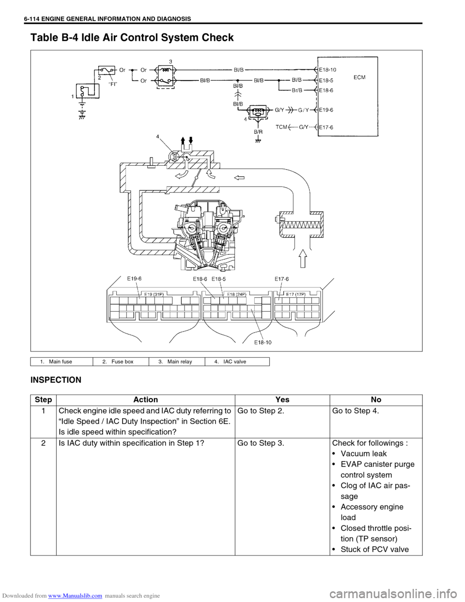
Table B-4 Idle Air Control System Check
INSPECTION
1. Main fuse 2. Fuse box 3. Main relay 4. IAC valve
Step Action Yes No
1 Check engine idle speed and IAC duty referring to
“Idle Speed / IAC Duty Inspection” in Section 6E.
Is idle speed within specification?Go to Step 2. Go to Step 4.
2 Is IAC duty within specification in Step 1? Go to Step 3. Check for followings :
Vacuum leak
EVAP canister purge
control system
Clog of IAC air pas-
sage
Accessory engine
load
Closed throttle posi-
tion (TP sensor)
Stuck of PCV valve
Page 634 of 687
Downloaded from www.Manualslib.com manuals search engine ENGINE AND EMISSION CONTROL SYSTEM 6E-29
Electronic Control System
Engine control module (ECM)
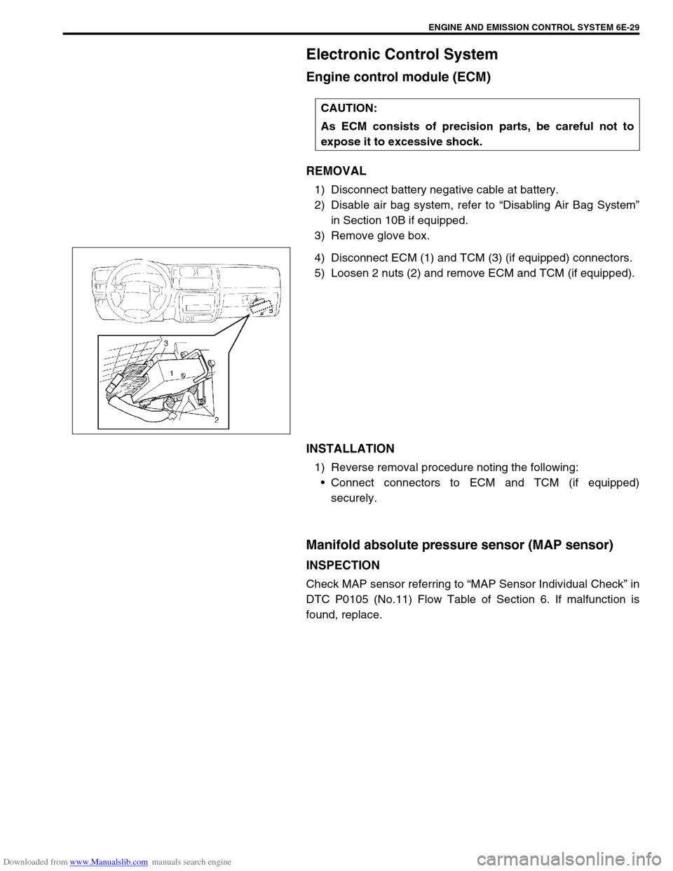
REMOVAL
1) Disconnect battery negative cable at battery.
2) Disable air bag system, refer to “Disabling Air Bag System”
in Section 10B if equipped.
3) Remove glove box.
4) Disconnect ECM (1) and TCM (3) (if equipped) connectors.
5) Loosen 2 nuts (2) and remove ECM and TCM (if equipped).
INSTALLATION
1) Reverse removal procedure noting the following:
Connect connectors to ECM and TCM (if equipped)
securely.
Manifold absolute pressure sensor (MAP sensor)
INSPECTION
Check MAP sensor referring to “MAP Sensor Individual Check” in
DTC P0105 (No.11) Flow Table of Section 6. If malfunction is
found, replace.CAUTION:
As ECM consists of precision parts, be careful not to
expose it to excessive shock.