cyl head SUZUKI JIMNY 2005 3.G Service Repair Manual
[x] Cancel search | Manufacturer: SUZUKI, Model Year: 2005, Model line: JIMNY, Model: SUZUKI JIMNY 2005 3.GPages: 687, PDF Size: 13.38 MB
Page 556 of 687
Downloaded from www.Manualslib.com manuals search engine ENGINE MECHANICAL (M13 ENGINE) 6A1-75
18) Remove heated oxygen sensor bracket from cylinder head
and detach No.1 heated oxygen sensor coupler from its
bracket.
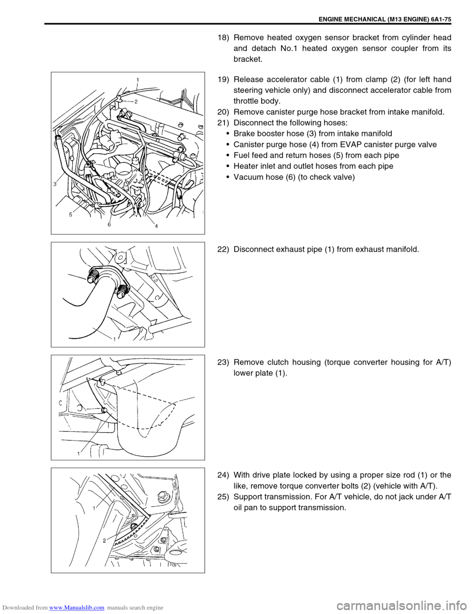
19) Release accelerator cable (1) from clamp (2) (for left hand
steering vehicle only) and disconnect accelerator cable from
throttle body.
20) Remove canister purge hose bracket from intake manifold.
21) Disconnect the following hoses:
Brake booster hose (3) from intake manifold
Canister purge hose (4) from EVAP canister purge valve
Fuel feed and return hoses (5) from each pipe
Heater inlet and outlet hoses from each pipe
Vacuum hose (6) (to check valve)
22) Disconnect exhaust pipe (1) from exhaust manifold.
23) Remove clutch housing (torque converter housing for A/T)
lower plate (1).
24) With drive plate locked by using a proper size rod (1) or the
like, remove torque converter bolts (2) (vehicle with A/T).
25) Support transmission. For A/T vehicle, do not jack under A/T
oil pan to support transmission.
Page 561 of 687

Downloaded from www.Manualslib.com manuals search engine 6A1-80 ENGINE MECHANICAL (M13 ENGINE)
REMOVAL
1) Remove engine assembly from vehicle as previously out-
lined.
2) Remove clutch cover, clutch disc and flywheel (drive plate
for A/T) by using special tool.
Special tool
(A) : 09924-17810
3) Remove the following parts from engine as previously out-
lined.
Oil pan and oil pump strainer
Intake manifold and exhaust manifold
Cylinder head cover
Timing chain cover
Timing chain guide, chain tensioner adjuster, chain ten-
sioner, timing chain and crankshaft timing sprocket
Camshaft, tappet and shim
Cylinder head assembly
Piston and connecting rod
4) Remove rear oil seal housing (1).
5) Loosen bearing cap No.1 and No.2 bolts in such order as
indicated in figure and remove them.
6) Remove crankshaft from cylinder block.
Page 573 of 687
Downloaded from www.Manualslib.com manuals search engine 6A1-92 ENGINE MECHANICAL (M13 ENGINE)
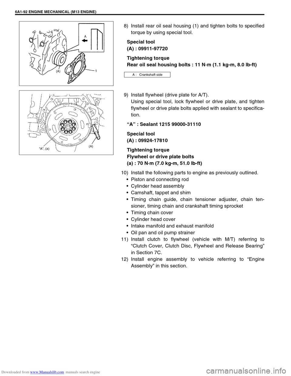
8) Install rear oil seal housing (1) and tighten bolts to specified
torque by using special tool.
Special tool
(A) : 09911-97720
Tightening torque
Rear oil seal housing bolts : 11 N·m (1.1 kg-m, 8.0 lb-ft)
9) Install flywheel (drive plate for A/T).
Using special tool, lock flywheel or drive plate, and tighten
flywheel or drive plate bolts applied with sealant to specifica-
tion.
“A” : Sealant 1215 99000-31110
Special tool
(A) : 09924-17810
Tightening torque
Flywheel or drive plate bolts
(a) : 70 N·m (7.0 kg-m, 51.0 lb-ft)
10) Install the following parts to engine as previously outlined.
Piston and connecting rod
Cylinder head assembly
Camshaft, tappet and shim
Timing chain guide, chain tensioner adjuster, chain ten-
sioner, timing chain and crankshaft timing sprocket
Timing chain cover
Cylinder head cover
Intake manifold and exhaust manifold
Oil pan and oil pump strainer
11) Install clutch to flywheel (vehicle with M/T) referring to
“Clutch Cover, Clutch Disc, Flywheel and Release Bearing”
in Section 7C.
12) Install engine assembly to vehicle referring to “Engine
Assembly” in this section.
A : Crankshaft side
Page 574 of 687

Downloaded from www.Manualslib.com manuals search engine ENGINE MECHANICAL (M13 ENGINE) 6A1-93
Required Service Material
Tightening Torque Specification
MaterialRecommended SUZUKI product
(Part Number)Use
Sealant SUZUKI BOND NO. 1207C
(99000-31150)To apply to mating surface of cylinder block and oil
pan.
To apply to mating surface of cylinder block and
timing chain cover.
To apply to sealing surface of cylinder head cover.
To apply to mating surface to rear oil seal housing.
SUZUKI BOND NO. 1207B
(99000-31140)To apply to mating surface of cylinder block, cylin-
der head and timing chain cover.
SUZUKI BOND NO. 1215
(99000-31110)To flywheel (M/T) or drive plate (A/T) bolts.
Fastening partTightening torque
Nm kg-m lb-ft
Oil pressure switch 14.0 1.4 10.5
Camshaft housing bolts
(for replacement of shim)8.0 0.8 6.0
Camshaft housing bolts 11.0 1.1 8.0
Cylinder head cover bolts 8.0 0.8 6.0
Intake manifold bolts and nuts 25.0 2.5 18.0
Exhaust manifold bolts and nuts 55.0 5.5 40.0
Exhaust pipe bolts 50.0 5.0 36.5
Exhaust manifold stiffener bolts 50.0 5.0 36.5
Oil pump strainer bolt 11.0 1.1 8.0
Oil pump strainer bracket bolt 11.0 1.1 8.0
Oil pan bolts and nuts 11.0 1.1 8.0
Oil pan drain plug 50.0 5.0 36.5
Timing chain cover bolts and nut 23.0 2.3 17.0
Crankshaft pulley bolt 150.0 15.0 108.5
Oil pump rotor plate bolts 11.0 1.1 8.0
Timing chain No.1 guide bolts 9.0 0.9 6.5
Timing chain tensioner adjuster bolts 11.0 1.1 8.0
Venturi plug 5.0 0.5 3.5
Cylinder head bolt for M8 22.0 2.2 16.0
Cylinder head bolts for M10 a) Tighten 40 N·m
b) Turn 60°
c) Turn 60°a) Tighten 4.0 kg-m
b) Turn 60°
c) Turn 60°a) Tighten 29.0 lb-ft
b) Turn 60°
c) Turn 60°
Connecting rod bearing cap nuts a) Tighten 15 N·m
b) Turn 45°
c) Turn 45°a) Tighten 1.5 kg-m
b) Turn 45°
c) Turn 45°a) Tighten 11.0 lb-ft
b) Turn 45°
c) Turn 45°
Engine mounting bolts 50.0 5.0 36.5
Page 579 of 687
Downloaded from www.Manualslib.com manuals search engine 6B-2 ENGINE COOLING
General Description
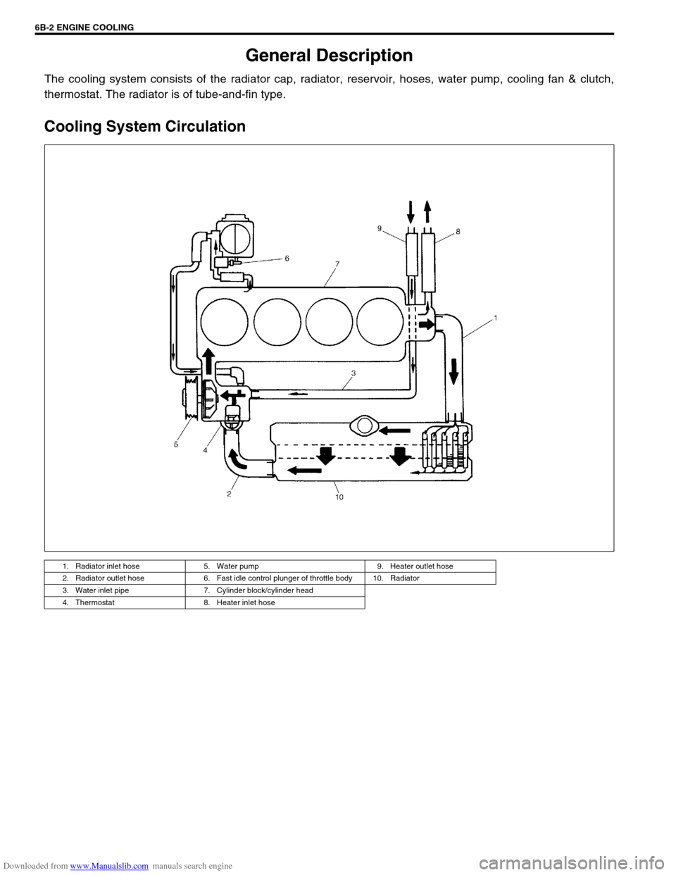
The cooling system consists of the radiator cap, radiator, reservoir, hoses, water pump, cooling fan & clutch,
thermostat. The radiator is of tube-and-fin type.
Cooling System Circulation
1. Radiator inlet hose 5. Water pump 9. Heater outlet hose
2. Radiator outlet hose 6. Fast idle control plunger of throttle body 10. Radiator
3. Water inlet pipe 7. Cylinder block/cylinder head
4. Thermostat 8. Heater inlet hose
Page 611 of 687
Downloaded from www.Manualslib.com manuals search engine 6E-6 ENGINE AND EMISSION CONTROL SYSTEM
Fuel Delivery System
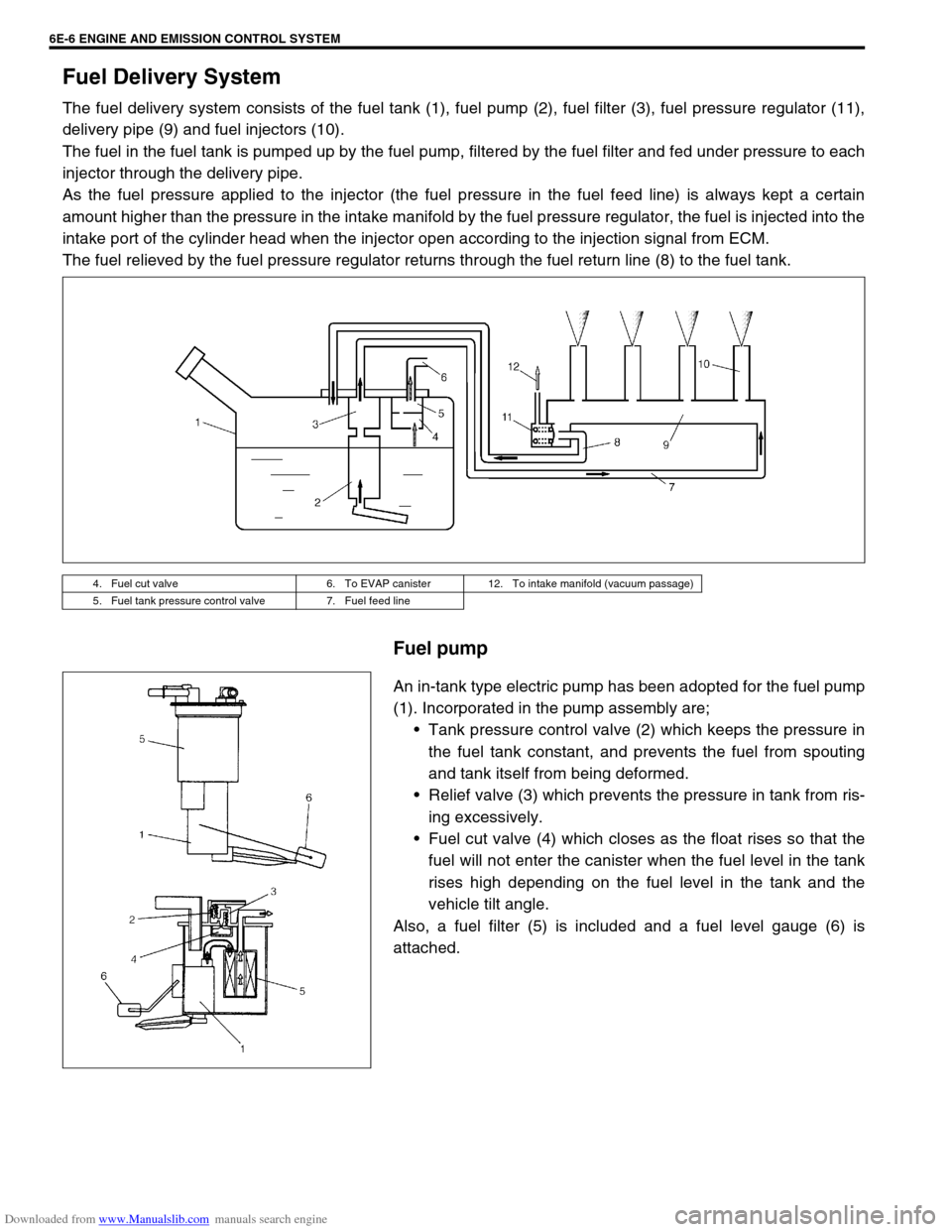
The fuel delivery system consists of the fuel tank (1), fuel pump (2), fuel filter (3), fuel pressure regulator (11),
delivery pipe (9) and fuel injectors (10).
The fuel in the fuel tank is pumped up by the fuel pump, filtered by the fuel filter and fed under pressure to each
injector through the delivery pipe.
As the fuel pressure applied to the injector (the fuel pressure in the fuel feed line) is always kept a certain
amount higher than the pressure in the intake manifold by the fuel pressure regulator, the fuel is injected into the
intake port of the cylinder head when the injector open according to the injection signal from ECM.
The fuel relieved by the fuel pressure regulator returns through the fuel return line (8) to the fuel tank.
Fuel pump
An in-tank type electric pump has been adopted for the fuel pump
(1). Incorporated in the pump assembly are;
Tank pressure control valve (2) which keeps the pressure in
the fuel tank constant, and prevents the fuel from spouting
and tank itself from being deformed.
Relief valve (3) which prevents the pressure in tank from ris-
ing excessively.
Fuel cut valve (4) which closes as the float rises so that the
fuel will not enter the canister when the fuel level in the tank
rises high depending on the fuel level in the tank and the
vehicle tilt angle.
Also, a fuel filter (5) is included and a fuel level gauge (6) is
attached.
4. Fuel cut valve 6. To EVAP canister 12. To intake manifold (vacuum passage)
5. Fuel tank pressure control valve 7. Fuel feed line
Page 639 of 687
Downloaded from www.Manualslib.com manuals search engine 6E-34 ENGINE AND EMISSION CONTROL SYSTEM
1) Disconnect negative cable at battery.
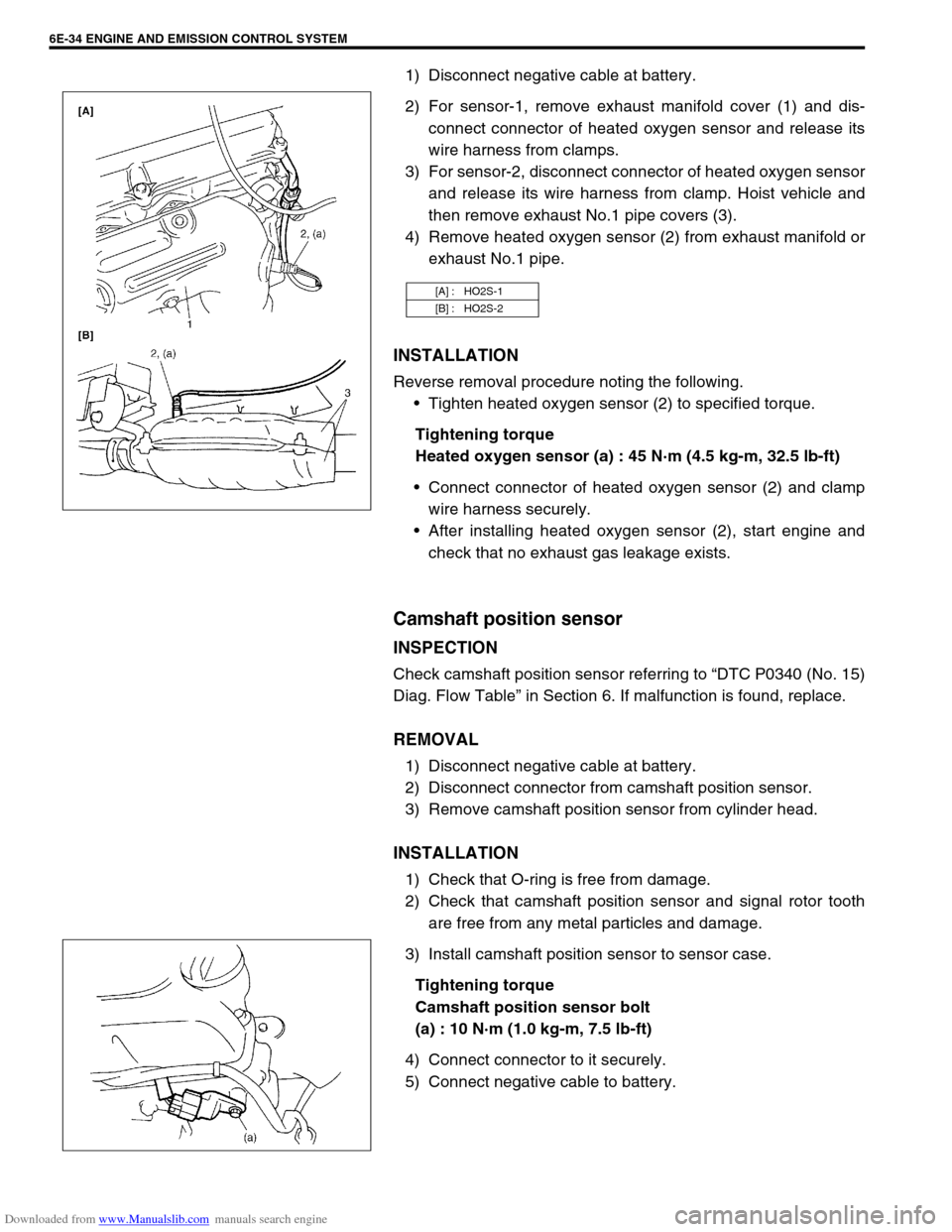
2) For sensor-1, remove exhaust manifold cover (1) and dis-
connect connector of heated oxygen sensor and release its
wire harness from clamps.
3) For sensor-2, disconnect connector of heated oxygen sensor
and release its wire harness from clamp. Hoist vehicle and
then remove exhaust No.1 pipe covers (3).
4) Remove heated oxygen sensor (2) from exhaust manifold or
exhaust No.1 pipe.
INSTALLATION
Reverse removal procedure noting the following.
Tighten heated oxygen sensor (2) to specified torque.
Tightening torque
Heated oxygen sensor (a) : 45 N·m (4.5 kg-m, 32.5 lb-ft)
Connect connector of heated oxygen sensor (2) and clamp
wire harness securely.
After installing heated oxygen sensor (2), start engine and
check that no exhaust gas leakage exists.
Camshaft position sensor
INSPECTION
Check camshaft position sensor referring to “DTC P0340 (No. 15)
Diag. Flow Table” in Section 6. If malfunction is found, replace.
REMOVAL
1) Disconnect negative cable at battery.
2) Disconnect connector from camshaft position sensor.
3) Remove camshaft position sensor from cylinder head.
INSTALLATION
1) Check that O-ring is free from damage.
2) Check that camshaft position sensor and signal rotor tooth
are free from any metal particles and damage.
3) Install camshaft position sensor to sensor case.
Tightening torque
Camshaft position sensor bolt
(a) : 10 N·m (1.0 kg-m, 7.5 lb-ft)
4) Connect connector to it securely.
5) Connect negative cable to battery.
[A] : HO2S-1
[B] : HO2S-2
Page 644 of 687
Downloaded from www.Manualslib.com manuals search engine ENGINE AND EMISSION CONTROL SYSTEM 6E-39
REMOVAL
1) Disconnect negative cable at battery.
2) Disconnect EGR valve connector.
3) Remove EGR pipe.
4) Remove EGR valve and gasket from cylinder head.
INSPECTION
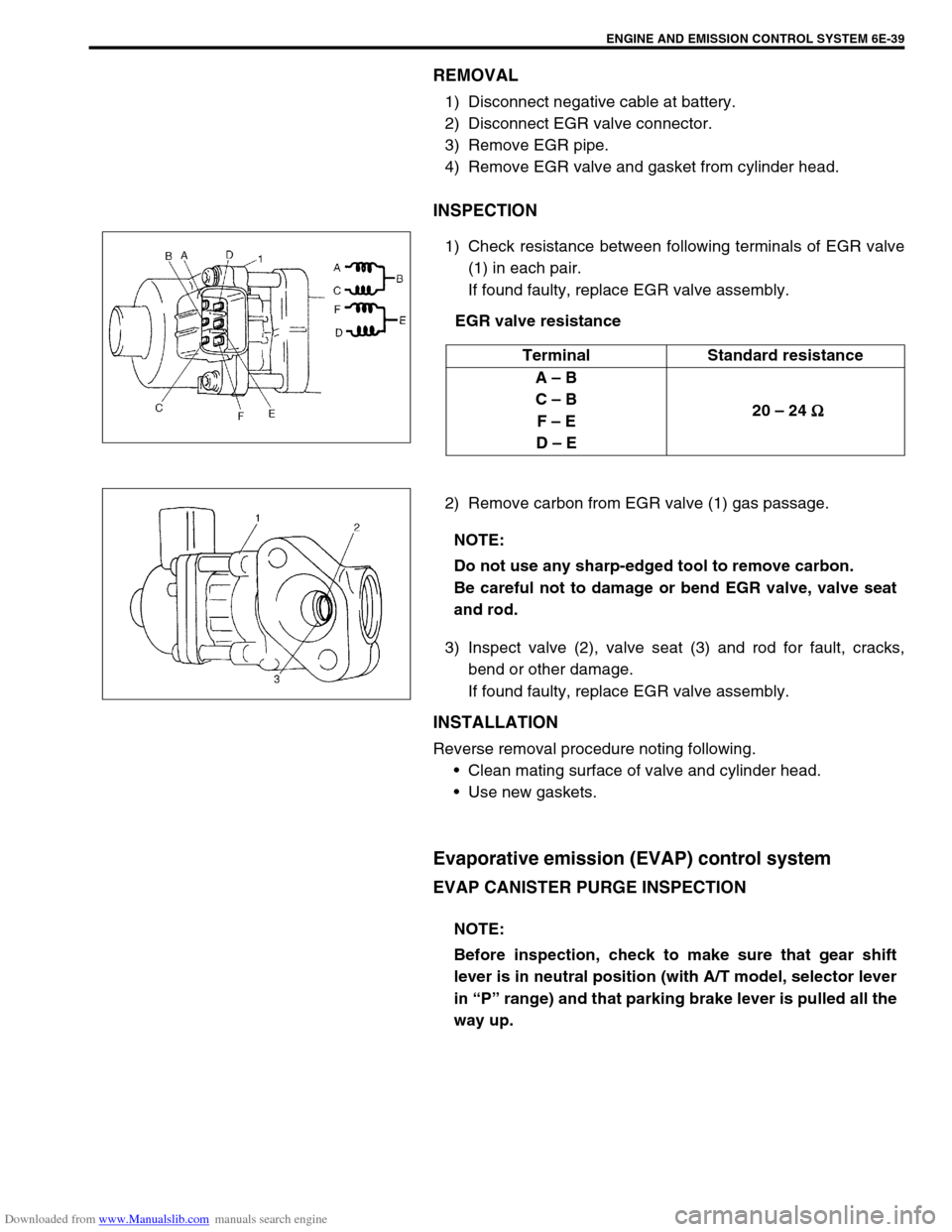
1) Check resistance between following terminals of EGR valve
(1) in each pair.
If found faulty, replace EGR valve assembly.
EGR valve resistance
2) Remove carbon from EGR valve (1) gas passage.
3) Inspect valve (2), valve seat (3) and rod for fault, cracks,
bend or other damage.
If found faulty, replace EGR valve assembly.
INSTALLATION
Reverse removal procedure noting following.
Clean mating surface of valve and cylinder head.
Use new gaskets.
Evaporative emission (EVAP) control system
EVAP CANISTER PURGE INSPECTION
Terminal Standard resistance
A – B
C – B
F – E
D – E 20 – 24
Ω
ΩΩ Ω
NOTE:
Do not use any sharp-edged tool to remove carbon.
Be careful not to damage or bend EGR valve, valve seat
and rod.
NOTE:
Before inspection, check to make sure that gear shift
lever is in neutral position (with A/T model, selector lever
in “P” range) and that parking brake lever is pulled all the
way up.
Page 646 of 687
Downloaded from www.Manualslib.com manuals search engine ENGINE AND EMISSION CONTROL SYSTEM 6E-41
EVAP CANISTER INSPECTION
1) Check outside of EVAP canister visually.
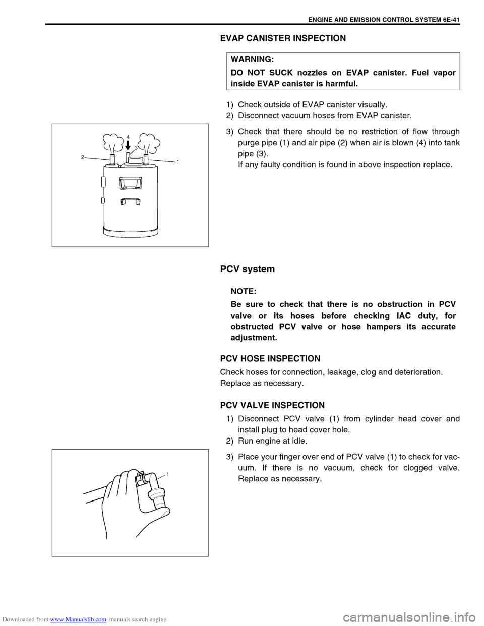
2) Disconnect vacuum hoses from EVAP canister.
3) Check that there should be no restriction of flow through
purge pipe (1) and air pipe (2) when air is blown (4) into tank
pipe (3).
If any faulty condition is found in above inspection replace.
PCV system
PCV HOSE INSPECTION
Check hoses for connection, leakage, clog and deterioration.
Replace as necessary.
PCV VALVE INSPECTION
1) Disconnect PCV valve (1) from cylinder head cover and
install plug to head cover hole.
2) Run engine at idle.
3) Place your finger over end of PCV valve (1) to check for vac-
uum. If there is no vacuum, check for clogged valve.
Replace as necessary. WARNING:
DO NOT SUCK nozzles on EVAP canister. Fuel vapor
inside EVAP canister is harmful.
NOTE:
Be sure to check that there is no obstruction in PCV
valve or its hoses before checking IAC duty, for
obstructed PCV valve or hose hampers its accurate
adjustment.
Page 654 of 687
Downloaded from www.Manualslib.com manuals search engine IGNITION SYSTEM (ELECTRONIC IGNITION SYSTEM 6F-5
On-Vehicle Service
Ignition Spark Test
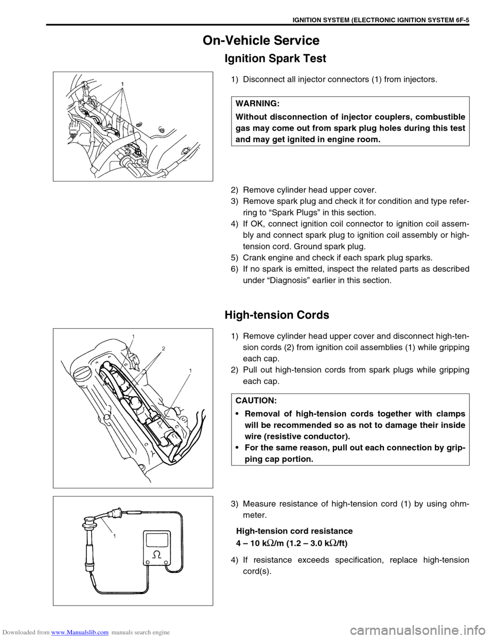
1) Disconnect all injector connectors (1) from injectors.
2) Remove cylinder head upper cover.
3) Remove spark plug and check it for condition and type refer-
ring to “Spark Plugs” in this section.
4) If OK, connect ignition coil connector to ignition coil assem-
bly and connect spark plug to ignition coil assembly or high-
tension cord. Ground spark plug.
5) Crank engine and check if each spark plug sparks.
6) If no spark is emitted, inspect the related parts as described
under “Diagnosis” earlier in this section.
High-tension Cords
1) Remove cylinder head upper cover and disconnect high-ten-
sion cords (2) from ignition coil assemblies (1) while gripping
each cap.
2) Pull out high-tension cords from spark plugs while gripping
each cap.
3) Measure resistance of high-tension cord (1) by using ohm-
meter.
High-tension cord resistance
4 – 10 k
Ω/m (1.2 – 3.0 kΩ/ft)
4) If resistance exceeds specification, replace high-tension
cord(s). WARNING:
Without disconnection of injector couplers, combustible
gas may come out from spark plug holes during this test
and may get ignited in engine room.
CAUTION:
Removal of high-tension cords together with clamps
will be recommended so as not to damage their inside
wire (resistive conductor).
For the same reason, pull out each connection by grip-
ping cap portion.