air condition SUZUKI JIMNY 2005 3.G Service Manual Online
[x] Cancel search | Manufacturer: SUZUKI, Model Year: 2005, Model line: JIMNY, Model: SUZUKI JIMNY 2005 3.GPages: 687, PDF Size: 13.38 MB
Page 268 of 687

Downloaded from www.Manualslib.com manuals search engine BRAKES 5-7
Brake warning light
turns on when brake
is appliedBrake fluid leaking from brake line Investigate leaky point, correct it
and add brake fluid.
Insufficient amount of brake fluid Add brake fluid.
Faulty P & Differential valve (Differential switch) Replace.
Brake warning light
fails to turn on even
when parking brake is
appliedBulb burnt out Replace bulb.
Brake warning light circuit open Repair circuit.
ABS warning light
does not turn on for 2
sec. after ignition
switch has turned ON.Bulb burnt out Replace bulb.
ABS warning light circuit open, if equipped with
ABS (including check relay)Check system referring to “TABLE-
A” in Section 5E.
ABS warning light
remains on after igni-
tion switch has turned
on for 2 sec.Malfunctioning ABS, if equipped with ABS Check system referring to “TABLE-
B” in Section 5E. Condition Possible Cause Correction
Page 273 of 687

Downloaded from www.Manualslib.com manuals search engine 5-12 BRAKES
If number of notches is out of specification, adjust cable by refer-
ring to adjustment procedure described on the following so as to
obtain specified parking brake stroke.
ADJUSTMENT
After confirming that above 5 conditions are all satisfied, adjust
parking brake lever stroke by loosening or tightening adjusting nut
(3) indicated in figure.
Parking brake stroke (when lever is pulled up at 200 N (20
kg, 44 Ibs) : 6 – 8 notches
Booster Operation Check
There are two ways to perform this inspection, with and without a
tester. Ordinarily, it is possible to roughly determine its condition
without using a tester.NOTE:
Check tooth tip of each notch for damage or wear. If any
damage or wear is found, replace parking brake lever.
NOTE:
Make sure for following conditions before cable adjust-
ment.
No air is trapped in brake system.
Brake pedal travel is proper.
Brake pedal has been depressed a few times with
about 30 kg (66 Ibs) load.
Parking brake lever (1) has been pulled up a few times
with about 20 kg force.
Rear brake shoes are not worn beyond limit, and self
adjusting mechanism operates properly.
NOTE:
Check brake drum for dragging after adjustment.
2. Brake cable
NOTE:
For this check, make sure that no air is in hydraulic line.
Page 275 of 687

Downloaded from www.Manualslib.com manuals search engine 5-14 BRAKES
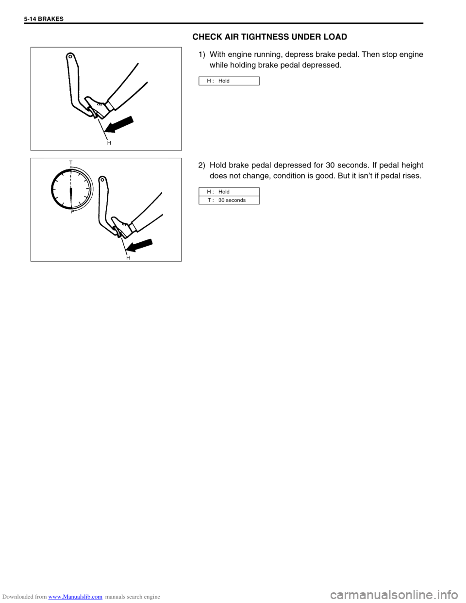
CHECK AIR TIGHTNESS UNDER LOAD
1) With engine running, depress brake pedal. Then stop engine
while holding brake pedal depressed.
2) Hold brake pedal depressed for 30 seconds. If pedal height
does not change, condition is good. But it isn’t if pedal rises.
H : Hold
H : Hold
T : 30 seconds
Page 279 of 687

Downloaded from www.Manualslib.com manuals search engine 5-18 BRAKES
4) When fluid pressure in the cylinder is almost depleted,
retighten bleeder plug.
5) Repeat this operation until there are no more air bubbles in
hydraulic line.
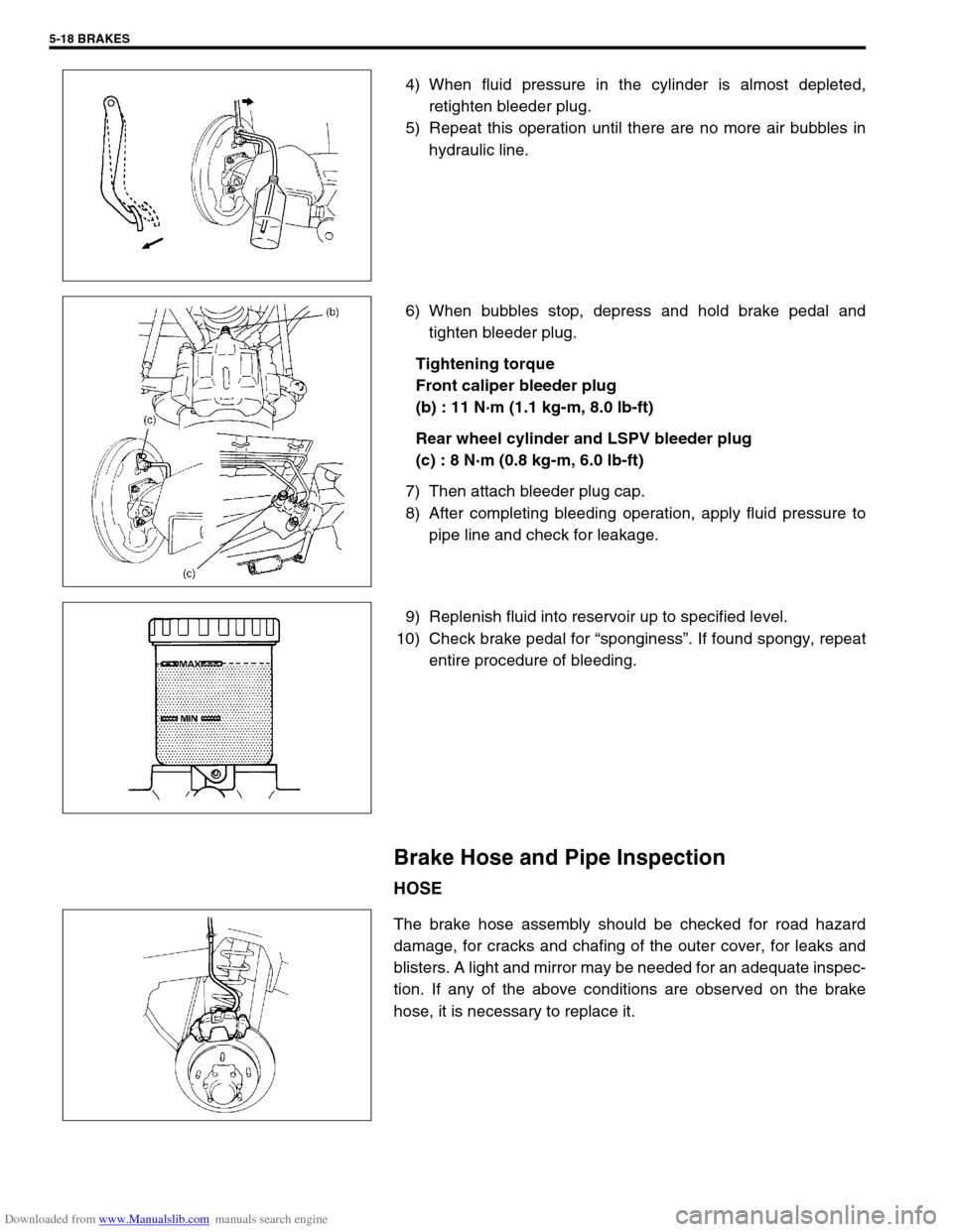
6) When bubbles stop, depress and hold brake pedal and
tighten bleeder plug.
Tightening torque
Front caliper bleeder plug
(b) : 11 N·m (1.1 kg-m, 8.0 lb-ft)
Rear wheel cylinder and LSPV bleeder plug
(c) : 8 N·m (0.8 kg-m, 6.0 lb-ft)
7) Then attach bleeder plug cap.
8) After completing bleeding operation, apply fluid pressure to
pipe line and check for leakage.
9) Replenish fluid into reservoir up to specified level.
10) Check brake pedal for “sponginess”. If found spongy, repeat
entire procedure of bleeding.
Brake Hose and Pipe Inspection
HOSE
The brake hose assembly should be checked for road hazard
damage, for cracks and chafing of the outer cover, for leaks and
blisters. A light and mirror may be needed for an adequate inspec-
tion. If any of the above conditions are observed on the brake
hose, it is necessary to replace it.
Page 325 of 687

Downloaded from www.Manualslib.com manuals search engine 5E-8 ANTILOCK BRAKE SYSTEM (ABS)
2) DRIVING TEST
Test drive the vehicle at 40 km/h for more than a minute and check if any trouble symptom (such as abnor-
mal lighting of “ABS” warning lamp) exists.
If the malfunction DTC is confirmed again at ignition switch ON, driving test as described in above is not nec-
essary. Proceed to Step 3.
3) DIAGNOSTIC TROUBLE CODE CHECK
Recheck diagnostic trouble code referring to “DTC Check” in this section.
4) DIAGNOSTIC TROUBLE CODE FLOW TABLE
According to Diagnostic Flow Table for the diagnostic trouble code confirmed in Step 3, locate the cause of
the trouble, namely in a sensor, switch, wire harness, connector, actuator, ABS control module or other part
and repair or replace faulty parts.
5)“DIAGNOSIS TABLE” IN SECTION 5
Check the parts or system suspected as a possible cause referring to “Diagnosis Table” in Section 5 and
based on symptoms appearing on the vehicle (symptoms obtained through Step 1)-a, 1)-b and 2) and repair
or replace faulty parts, if any.
6) CHECK FOR INTERMITTENT PROBLEM
Check parts where an intermittent trouble is easy to occur (e.g., wire harness, connector, etc.), referring to
Intermittent Trouble in Section 0A and related circuit of trouble code recorded in Step 1)-c.
7) FINAL CONFIRMATION TEST
Confirm that the problem symptom has gone and the ABS is free from any abnormal conditions. If what has
been repaired is related to the malfunction DTC, clear the DTC once and perform test driving and confirm
that a normal code is indicated.
Page 332 of 687

Downloaded from www.Manualslib.com manuals search engine ANTILOCK BRAKE SYSTEM (ABS) 5E-15
Table – B “ABS” Warning Lamp Circuit Check – Lamp Comes “ON” Steady
Refer to TABLE – A for System Circuit Diagram and Circuit Description.
INSPECTION
3 1) Remove combination meter.
Is bulb of ABS warning lamp in good condition?“R/Bl” circuit shorted to ground.
If OK, replace ABS warning cir-
cuit (lamp driver module).Replace bulb.
4 Is IG fuse in good condition? Open in “B/W” wire to combina-
tion meter or poor connection.Repair and replace. Step Action Yes No
Step Action Yes No
1 Perform diagnostic trouble code check. Is there
any DTC (including code No.12, NO CODES on
SUZUKI scan tool) exists?Go to step 2. Go to step 3.
2 Is malfunction DTC (other than code No.12)
exists at step 1?Go to step 7 of ABS diag-
nostic flow table in this
section.Go to step 3.
3 1) Disconnect ABS hydraulic unit / control
module connector.
2) Check for proper connection to ABS hydrau-
lic unit / control module connector at termi-
nals “A14” and “A18”.
3) If OK, turn ignition switch “ON” and mea-
sure voltage at terminal “A18” of connector.
Is it 10 – 14 V?Go to step 4.“B/W” circuit open.
4 1) With ABS control module connector discon-
nected, turn ignition switch ON and light
ABS warning lamp.
2) Connect terminal “A14” of disconnected
connector to ground using service wire.
Does “ABS warning lamp” turn off?Go to step 5.“R/Bl” circuit open.
If wire and connection are
OK, replace ABS lamp
driver module.
5 1) Measure resistance from connector termi-
nal “A24” to body ground.
Is continuity indicated?Substitute a known-good
ABS hydraulic unit / con-
trol module assembly and
recheck.“B” circuit open.
Page 334 of 687

Downloaded from www.Manualslib.com manuals search engine ANTILOCK BRAKE SYSTEM (ABS) 5E-17
Table – D Code (DTC) is Not Outputted Even With Diag. Switch Terminal Con-
nected to Ground.
CIRCUIT DESCRIPTION
When the diag. switch terminal is connected to the ground with the ignition switch turned ON, the ABS control
module outputs a diagnostic trouble code by flashing “ABS” warning lamp.
INSPECTION
1.“ABS” warning lamp in combination meter 3-1. Diag. switch terminal 4-1. Lock position
2. ABS hydraulic unit / control module assembly 3-2. Diag. ground terminal 4-2. Unlock position
3. Monitor connector 4. ABS hydraulic unit / control module connector of harness
Step Action Yes No
1 Is it shorted diag. switch terminal and ground
terminal by service wire properly?Go to step 2. Connect service wire
securely.
2 1) Disconnect service wire.
2) Disconnect ABS hydraulic unit / control
module connector.
3) Measure resistance between diag. switch
terminal and connector terminal “A12”.
Is it infinite (∞)?“P/B” circuit open. Go to step 3.
3 1) Measure resistance between ground termi-
nal of monitor connector and body ground.
Is continuity indicated?Go to step 4.“B” circuit open or poor
connection.
4 1) Check for proper connection to ABS hydrau-
lic unit / control module at terminal “A12”
and “A24”.
2) If OK, then check “ABS” warning lamp cir-
cuit referring to TABLE A, B and C.
Is it in good condition?Substitute a known-good
ABS hydraulic unit / con-
trol module assembly and
recheck.Repair “ABS” warning
lamp circuit.
Page 338 of 687

Downloaded from www.Manualslib.com manuals search engine ANTILOCK BRAKE SYSTEM (ABS) 5E-21
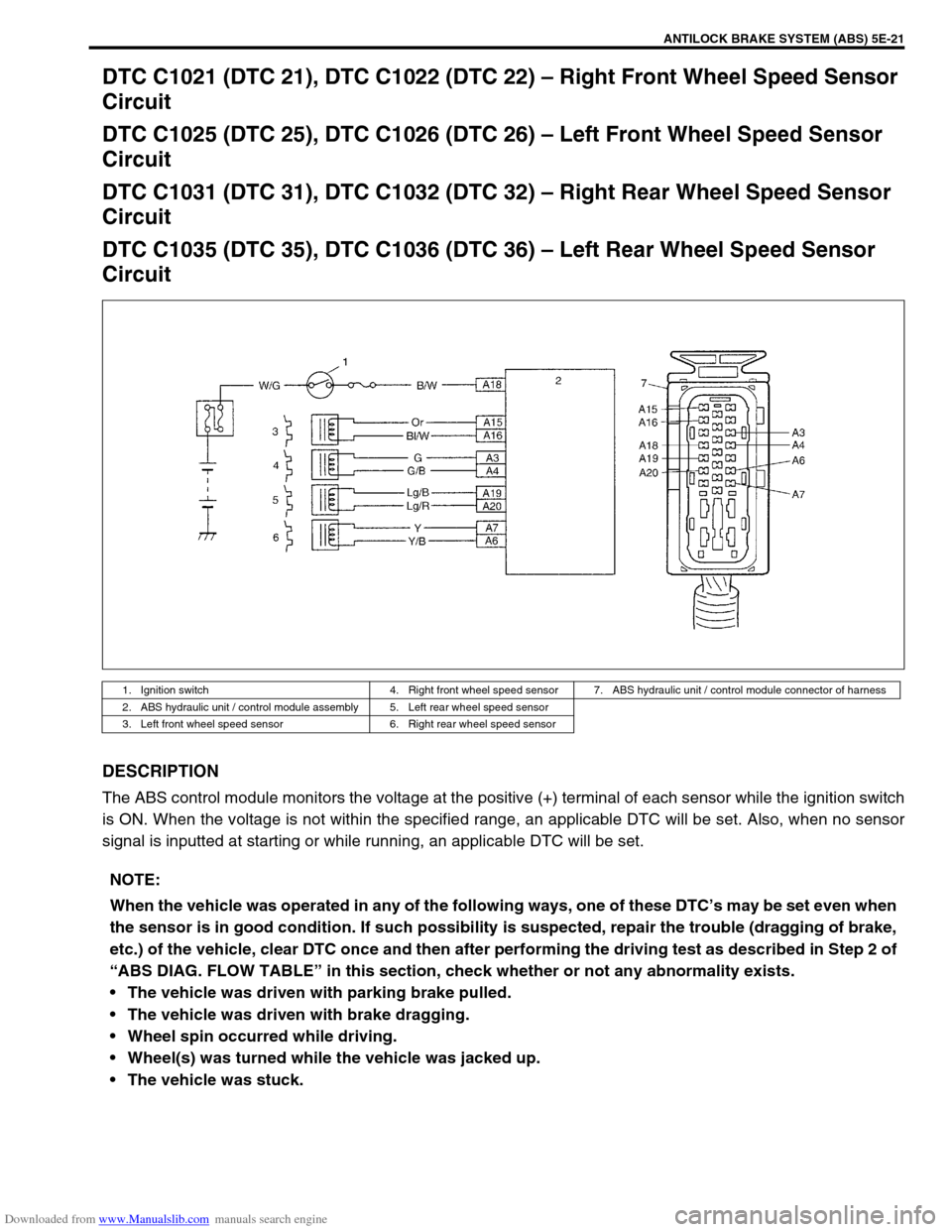
DTC C1021 (DTC 21), DTC C1022 (DTC 22) – Right Front Wheel Speed Sensor
Circuit
DTC C1025 (DTC 25), DTC C1026 (DTC 26) – Left Front Wheel Speed Sensor
Circuit
DTC C1031 (DTC 31), DTC C1032 (DTC 32) – Right Rear Wheel Speed Sensor
Circuit
DTC C1035 (DTC 35), DTC C1036 (DTC 36) – Left Rear Wheel Speed Sensor
Circuit
DESCRIPTION
The ABS control module monitors the voltage at the positive (+) terminal of each sensor while the ignition switch
is ON. When the voltage is not within the specified range, an applicable DTC will be set. Also, when no sensor
signal is inputted at starting or while running, an applicable DTC will be set.
1. Ignition switch 4. Right front wheel speed sensor 7. ABS hydraulic unit / control module connector of harness
2. ABS hydraulic unit / control module assembly 5. Left rear wheel speed sensor
3. Left front wheel speed sensor 6. Right rear wheel speed sensor
NOTE:
When the vehicle was operated in any of the following ways, one of these DTC’s may be set even when
the sensor is in good condition. If such possibility is suspected, repair the trouble (dragging of brake,
etc.) of the vehicle, clear DTC once and then after performing the driving test as described in Step 2 of
“ABS DIAG. FLOW TABLE” in this section, check whether or not any abnormality exists.
The vehicle was driven with parking brake pulled.
The vehicle was driven with brake dragging.
Wheel spin occurred while driving.
Wheel(s) was turned while the vehicle was jacked up.
The vehicle was stuck.
Page 339 of 687

Downloaded from www.Manualslib.com manuals search engine 5E-22 ANTILOCK BRAKE SYSTEM (ABS)
INSPECTION
Step Action Yes No
1 1) Disconnect the applicable sensor connector with ignition
switch OFF.
2) Measure resistance between sensor terminals.
Resistance of wheel speed sensor: 1.4 – 1.8 kΩ (at
20°C, 68°F)
3) Measure resistance between each terminal and body
ground.
Insulation resistance: 1MΩ or higher
Were measured resistance values in step 2) and 3) as spec-
ified? (See [A])Go to step 2. Replace sensor.
2 1) Ignition switch OFF.
2) Disconnect connector from ABS hydraulic unit / control
module assembly. (See [B])
3) Check for proper connection to ABS hydraulic unit / con-
trol module assembly at each sensor terminal.
4) If OK, then turn ignition switch ON and measure voltage
between sensor positive terminal of module connector
and body ground.
Is it 0V?Go to step 3. Sensor positive cir-
cuit shorted to
power.
3 1) Ignition switch OFF.
2) Connect connector to sensor.
3) Measure resistance between sensor terminals at mod-
ule connector.
4) Measure resistance between sensor positive terminal
and negative terminal of module connector, between
positive terminal and body ground.
Are measured resistance values within each specified range
described in above step 1?Go to step 4. Circuit open or
shorted to ground.
4 1) Remove wheel speed sensor.
2) Check sensor for damage or foreign material being
attached.
Is it in good condition? (See [C])Go to step 5. Clean or replace
sensor.
5 Check visually through wheel speed sensor installation hole
for following.
Ring serration (teeth) neither missing or damaged.
No foreign material being attached.
Ring not being eccentric.
Wheel bearing free from excessive play.
Are they in good condition? (See [D])Go to step 6. Clean, repair or
replace.
6 1) Install sensor to knuckle or axle housing.
2) Tighten sensor bolt to specified torque and check that
there is not any clearance between sensor and knuckle
or axle housing. (See [E])
Replace sensor if any.
Referring to “Front Wheel Speed Sensor” in this section,
check output voltage or waveform of sensor. Is proper out-
put voltage or waveform obtained?Substitute a known-
good ABS hydraulic
unit / control module
assembly and
recheck.Replace sensor and
recheck.
Page 342 of 687

Downloaded from www.Manualslib.com manuals search engine ANTILOCK BRAKE SYSTEM (ABS) 5E-25
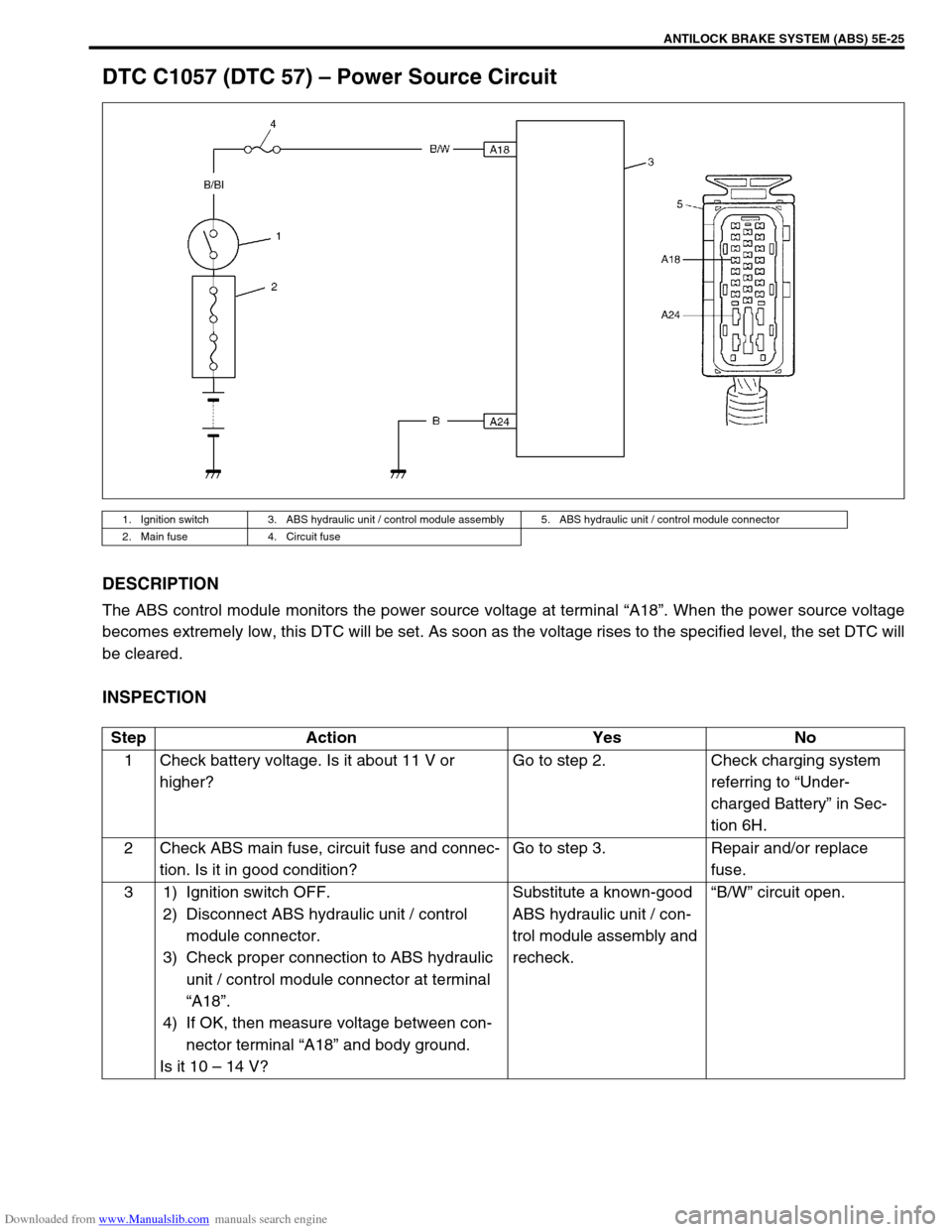
DTC C1057 (DTC 57) – Power Source Circuit
DESCRIPTION
The ABS control module monitors the power source voltage at terminal “A18”. When the power source voltage
becomes extremely low, this DTC will be set. As soon as the voltage rises to the specified level, the set DTC will
be cleared.
INSPECTION
1. Ignition switch 3. ABS hydraulic unit / control module assembly 5. ABS hydraulic unit / control module connector
2. Main fuse 4. Circuit fuse
Step Action Yes No
1 Check battery voltage. Is it about 11 V or
higher?Go to step 2. Check charging system
referring to “Under-
charged Battery” in Sec-
tion 6H.
2 Check ABS main fuse, circuit fuse and connec-
tion. Is it in good condition?Go to step 3. Repair and/or replace
fuse.
3 1) Ignition switch OFF.
2) Disconnect ABS hydraulic unit / control
module connector.
3) Check proper connection to ABS hydraulic
unit / control module connector at terminal
“A18”.
4) If OK, then measure voltage between con-
nector terminal “A18” and body ground.
Is it 10 – 14 V?Substitute a known-good
ABS hydraulic unit / con-
trol module assembly and
recheck.“B/W” circuit open.