Cluster SUZUKI JIMNY 2005 3.G Service Workshop Manual
[x] Cancel search | Manufacturer: SUZUKI, Model Year: 2005, Model line: JIMNY, Model: SUZUKI JIMNY 2005 3.GPages: 687, PDF Size: 13.38 MB
Page 58 of 687

Downloaded from www.Manualslib.com manuals search engine HEATER AND VENTILATION 1A-5
Heater Blower Resistor
REMOVAL
1) Disconnect negative (–) cable at battery.
2) Disable air bag system, if equipped.
Refer to “Disabling Air Bag System” in Section 10B.
3) Disconnect resistor coupler.
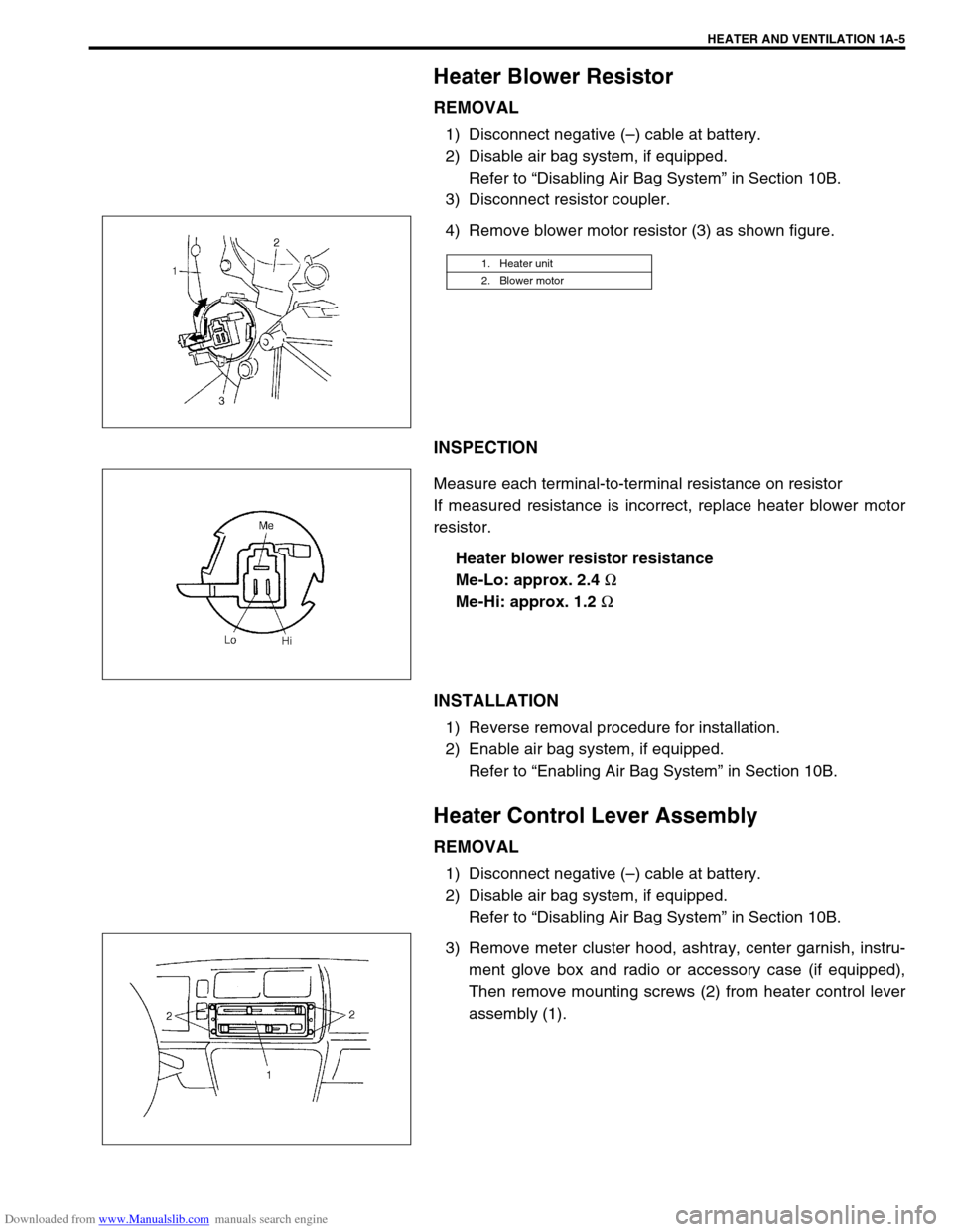
4) Remove blower motor resistor (3) as shown figure.
INSPECTION
Measure each terminal-to-terminal resistance on resistor
If measured resistance is incorrect, replace heater blower motor
resistor.
Heater blower resistor resistance
Me-Lo: approx. 2.4
Ω
Me-Hi: approx. 1.2
Ω
INSTALLATION
1) Reverse removal procedure for installation.
2) Enable air bag system, if equipped.
Refer to “Enabling Air Bag System” in Section 10B.
Heater Control Lever Assembly
REMOVAL
1) Disconnect negative (–) cable at battery.
2) Disable air bag system, if equipped.
Refer to “Disabling Air Bag System” in Section 10B.
3) Remove meter cluster hood, ashtray, center garnish, instru-
ment glove box and radio or accessory case (if equipped),
Then remove mounting screws (2) from heater control lever
assembly (1).
1. Heater unit
2. Blower motor
Page 363 of 687

Downloaded from www.Manualslib.com manuals search engine 6-6 ENGINE GENERAL INFORMATION AND DIAGNOSIS
Engine Diagnosis
General Description
This vehicle is equipped with an engine and emission control system which are under control of ECM.
The engine and emission control system in this vehicle are controlled by ECM. ECM has an On-Board Diagnos-
tic system which detects a malfunction in this system and abnormality of those parts that influence the engine
exhaust emission. When diagnosing engine troubles, be sure to have full understanding of the outline of “On-
Board Diagnostic System” and each item in “Precaution in Diagnosing Trouble” and execute diagnosis accord-
ing to “ENGINE DIAGNOSTIC FLOW TABLE”.
There is a close relationship between the engine mechanical, engine cooling system, ignition system, exhaust
system, etc. and the engine and emission control system in their structure and operation. In case of an engine
trouble, even when the malfunction indicator lamp (MIL) doesn’t turn ON, it should be diagnosed according to
this flow table.
On-Board Diagnostic System (Vehicle with
Immobilizer Indicator Lamp)
ECM in this vehicle has following functions.
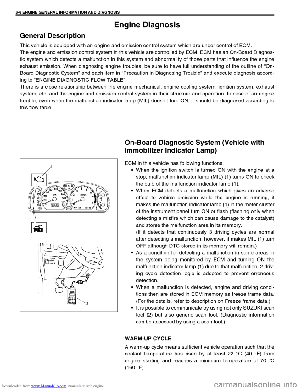
When the ignition switch is turned ON with the engine at a
stop, malfunction indicator lamp (MIL) (1) turns ON to check
the bulb of the malfunction indicator lamp (1).
When ECM detects a malfunction which gives an adverse
effect to vehicle emission while the engine is running, it
makes the malfunction indicator lamp (1) in the meter cluster
of the instrument panel turn ON or flash (flashing only when
detecting a misfire which can cause damage to the catalyst)
and stores the malfunction area in its memory.
(If it detects that continuously 3 driving cycles are normal
after detecting a malfunction, however, it makes MIL (1) turn
OFF although DTC stored in its memory will remain.)
As a condition for detecting a malfunction in some areas in
the system being monitored by ECM and turning ON the
malfunction indicator lamp (1) due to that malfunction, 2 driv-
ing cycle detection logic is adopted to prevent erroneous
detection.
When a malfunction is detected, engine and driving condi-
tions then are stored in ECM memory as freeze frame data.
(For the details, refer to description on Freeze frame data.)
It is possible to communicate by using not only SUZUKI scan
tool (2) but also generic scan tool. (Diagnostic information
can be accessed by using a scan tool.)
WARM-UP CYCLE
A warm-up cycle means sufficient vehicle operation such that the
coolant temperature has risen by at least 22 °C (40 °F) from
engine starting and reaches a minimum temperature of 70 °C
(160 °F).
Page 581 of 687

Downloaded from www.Manualslib.com manuals search engine 6B-4 ENGINE COOLING
Water Pump
The centrifugal type water pump is used in the cooling system.
The pump impeller is supported by a totally sealed bearing.
The water pump can not be disassembled.
Thermostat
A wax pellet type thermostat is used in the cooling system.
The temperature at which the valve begins to open is stamped on
thermostat.
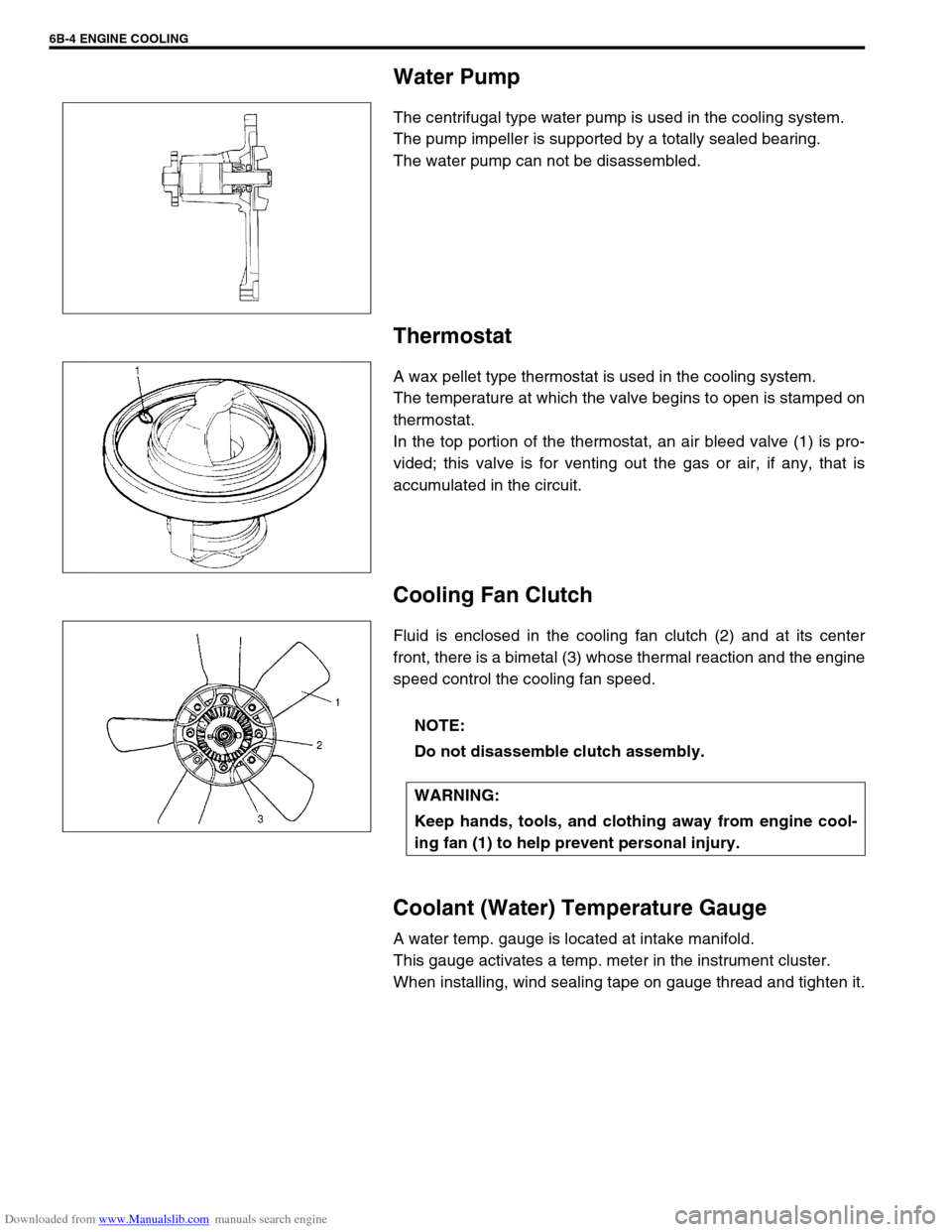
In the top portion of the thermostat, an air bleed valve (1) is pro-
vided; this valve is for venting out the gas or air, if any, that is
accumulated in the circuit.
Cooling Fan Clutch
Fluid is enclosed in the cooling fan clutch (2) and at its center
front, there is a bimetal (3) whose thermal reaction and the engine
speed control the cooling fan speed.
Coolant (Water) Temperature Gauge
A water temp. gauge is located at intake manifold.
This gauge activates a temp. meter in the instrument cluster.
When installing, wind sealing tape on gauge thread and tighten it.
NOTE:
Do not disassemble clutch assembly.
WARNING:
Keep hands, tools, and clothing away from engine cool-
ing fan (1) to help prevent personal injury.