Speed sensor SUZUKI JIMNY 2005 3.G Service Workshop Manual
[x] Cancel search | Manufacturer: SUZUKI, Model Year: 2005, Model line: JIMNY, Model: SUZUKI JIMNY 2005 3.GPages: 687, PDF Size: 13.38 MB
Page 26 of 687

Downloaded from www.Manualslib.com manuals search engine GENERAL INFORMATION 0A-21
Abbreviations May Be Used In This Manual
Abbreviations
AABC
ATDC
API
ATF
ALR
AC
A/T
A/C
ABDC
A/F
A-ELRAnti-lock Brake System
After Top Dead Center
American Petroleum Institute
Automatic Transmission Fluid
Automatic Locking Retractor
Alternating Current
Automatic Transmission
Air Conditioning
After Bottom Dead Center
Air Fuel Mixture Ratio
Automatic-Emergency
Locking RetractorEEBCM
ECM
ECT Sensor
EGR
EGRT Sensor
EFE Heater
ELR
EPS
EVAP
EVAP CanisterElectronic Brake Control Module,
ABS Control Module
Engine Control Module
Engine Coolant Temperature
Sensor (Water Temp. Sensor,
WTS)
Exhaust Gas Recirculation
EGR Temperature Sensor
(Recirculated Exhaust Gas Temp.
Sensor, REGTS)
Early Fuel Evaporation
Heater (Positive Temperature
Coefficient, PTC Heater)
Emergency Locking Retractor
Electronic Power Steering
Evaporative Emission
Evaporative Emission Canister
(Charcoal Canister) BB+
BTDC
BBDCBattery Positive Voltage
Before Top Dead Center
Before Bottom Dead Center
CCKT
CMP Sensor
CO
CPP Switch
CPU
CRSCircuit
Camshaft Position Sensor
(Crank Angle Sensor, CAS)
Carbon Monoxide
Clutch Pedal Position Switch
(Clutch Switch, Clutch Start
Switch)
Central Processing Unit
Child Restraint SystemF 4WD 4 Wheel Drive
GGEN
GNDGenerator
Ground
HHC
HO2SHydrocarbons
Heated Oxygen Sensor
DDC
DLC
DOHC
DOJ
DRL
DTCDirect Current
Data Link Connector
(Assembly Line Diag. Link, ALDL,
Serial Data Link, SDL)
Double Over Head Camshaft
Double Offset Joint
Daytime Running Light
Diagnostic Trouble Code
(Diagnostic Code)IIAC Valve
IAT Sensor
ICM
IG
ISC ActuatorIdle Air Control Valve (Idle Speed
Control Solenoid Valve, ISC
Solenoid Valve)
Intake Air Temperature Sensor
(Air temperature Sensor, ATS)
Immobilizer Control Module
Ignition
Idle Speed Control Actuator
(Motor)
Page 27 of 687

Downloaded from www.Manualslib.com manuals search engine 0A-22 GENERAL INFORMATION
LLH
LSPVLeft Hand
Load Sensing Proportioning Valve
TTBI
TCC
TCM
TP Sensor
TVV
TWC
2WDThrottle Body Fuel Injection
(Single-Point Fuel Injection, SPI)
Torque Converter Clutch
Transmission Control Module
(A/T Controller, A/T Control Mod-
ule)
Throttle Position Sensor
Thermal Vacuum Valve
(Thermal Vacuum Switching Valve,
TVSV, Bimetal Vacuum Switching
Valve, BVSV)
Three Way Catalytic Converter
(Three Way Catalyst)
2 Wheel Drive MMAF Sensor
MAP Sensor
Max
MFI
Min
MIL
M/TMass Air Flow Sensor
(Air Flow Sensor, AFS, Air Flow
Meter, AFM)
Manifold Absolute Pressure
Sensor (Pressure Sensor, PS)
Maximum
Multiport Fuel Injection
(Multipoint Fuel Injection)
Minimum
Malfunction Indicator Lamp
(“CHECK ENGINE” Light)
Manual Transmission
N NOx Nitrogen Oxides VVIN
VSSVehicle Identification Number
Vehicle Speed Sensor
OOBD
O/D
OHCOn-Board Diagnostic System
(Self-Diagnosis Function)
Overdrive
Over Head CamshaftWWU-OC
WU-TWCWarm Up Oxidation Catalytic
Converter
Warm Up Three Way Catalytic
Converter
PPNP
P/S
PSP Switch
PCM
PCVPark/Neutral Position
Power Steering
Power Steering Pressure Switch
(P/S Pressure Switch)
Powertrain Control Module
Positive Crankcase Ventilation
R RH Right Hand
SSAE
SDM
SFI
SOHCSociety of Automotive Engineers
Sensing and Diagnostic Module
(Air bag controller, Air bag control
module)
Sequential Multiport Fuel Injection
Single Over Head Camshaft
Page 80 of 687

Downloaded from www.Manualslib.com manuals search engine AIR CONDITIONING (OPTIONAL) 1B-19
ECM VOLTAGE VALUES TABLE FOR RELATION OF A/C CONTROL
Terminal Wire CircuitMeasurement
groundNormal value Condition
E18-1 PCompressor
magnet clutch
outputGround to
engine (Fig B)10 – 14 voltBlower fan motor switch and A/C
switch ON with engine running
0 – 1 voltsExcept the above-mentioned condi-
tion with engine running
E18-5 Bl/BMain power sup-
ply for ECMGround to
engine (Fig B)10 – 14 voltsIgnition switch ON with engine
stopped
E18-6 Bl/BMain power sup-
ply for ECMGround to
engine (Fig B)10 – 14 voltsIgnition switch ON with engine
stopped
E18-10 Bl Main relay driveGround to
engine (Fig B)0.5 – 1.2 voltIgnition switch ON with engine
stopped
0 volts Ignition switch OFF
E18-16 G/W A/C switch inputGround to
engine (Fig B)12 – 15 voltsBlower fan motor switch or A/C switch
OFF with engine running
0 – 1 voltBlower fan motor switch and A/C
switch ON with engine running
12 – 15 voltsWithin several seconds after operate
transfer lever between 2WD and 4WD
with above condition
E18-18 P/BCompressor
cooling fan relay
outputGround to
engine (Fig B)0 – 1 voltBlower fan motor switch and A/C
switch ON or engine coolant tempera-
ture at more than 110 °C (230 °F) with
engine running.
12 – 15 voltsExcept the above-mentioned condi-
tion with engine running
E18-20 B/BlSensor ground
for A/C evapora-
torGround to
body (Fig A)–0.5 – 0 volt Engine running
E18-24 Bl/YBlower fan
speed inputGround to
engine (Fig B)0 – 1 voltBlower fan motor switch 2nd or 3rd
with engine running
4 – 7 voltsBlower fan motor switch 1st with
engine running
12 – 15 voltsBlower fan motor switch and A/C
switch OFF with engine running
E19-1 BMain ground for
ECMGround to
engine (Fig A)–0.5 – 1 volt Engine running
E19-2 B/RECM ground for
power circuitGround to
engine (Fig A)–0.5 – 1 volt Engine running
E19-3 B/RECM ground for
power circuitGround to
engine (Fig A)–0.5 – 1 volt Engine running
E19-10 B/BlSensor ground
for ECT sensorGround to
body (Fig A)–0.5 – 1 volt Engine running
Page 192 of 687
Downloaded from www.Manualslib.com manuals search engine FRONT SUSPENSION 3D-19
Front Shock Absorber
REMOVAL
1) Hoist vehicle.
2) Support front axle housing by using floor jack to prevent it
from lowering, refer to “When Using Floor Jack” under “Vehi-
cle Lifting Points” in Section 0A.
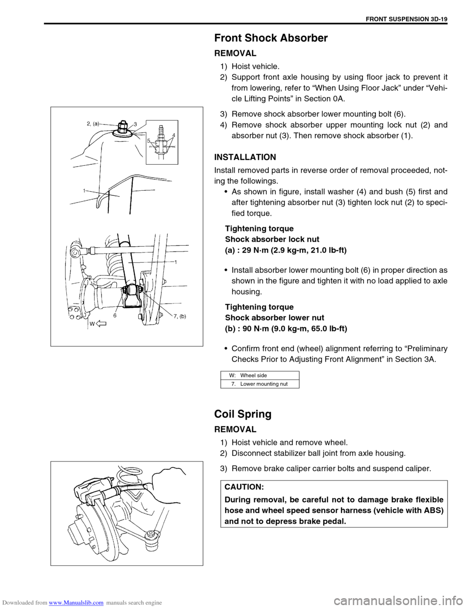
3) Remove shock absorber lower mounting bolt (6).
4) Remove shock absorber upper mounting lock nut (2) and
absorber nut (3). Then remove shock absorber (1).
INSTALLATION
Install removed parts in reverse order of removal proceeded, not-
ing the followings.
As shown in figure, install washer (4) and bush (5) first and
after tightening absorber nut (3) tighten lock nut (2) to speci-
fied torque.
Tightening torque
Shock absorber lock nut
(a) : 29 N·m (2.9 kg-m, 21.0 lb-ft)
Install absorber lower mounting bolt (6) in proper direction as
shown in the figure and tighten it with no load applied to axle
housing.
Tightening torque
Shock absorber lower nut
(b) : 90 N·m (9.0 kg-m, 65.0 lb-ft)
Confirm front end (wheel) alignment referring to “Preliminary
Checks Prior to Adjusting Front Alignment” in Section 3A.
Coil Spring
REMOVAL
1) Hoist vehicle and remove wheel.
2) Disconnect stabilizer ball joint from axle housing.
3) Remove brake caliper carrier bolts and suspend caliper.
W: Wheel side
7. Lower mounting nut
CAUTION:
During removal, be careful not to damage brake flexible
hose and wheel speed sensor harness (vehicle with ABS)
and not to depress brake pedal.
Page 211 of 687
Downloaded from www.Manualslib.com manuals search engine 3D-38 FRONT SUSPENSION
Front Axle Housing
REMOVAL
1) Hoist vehicle.
2) Remove front wheels.
3) Drain front differential gear oil (for 4WD).
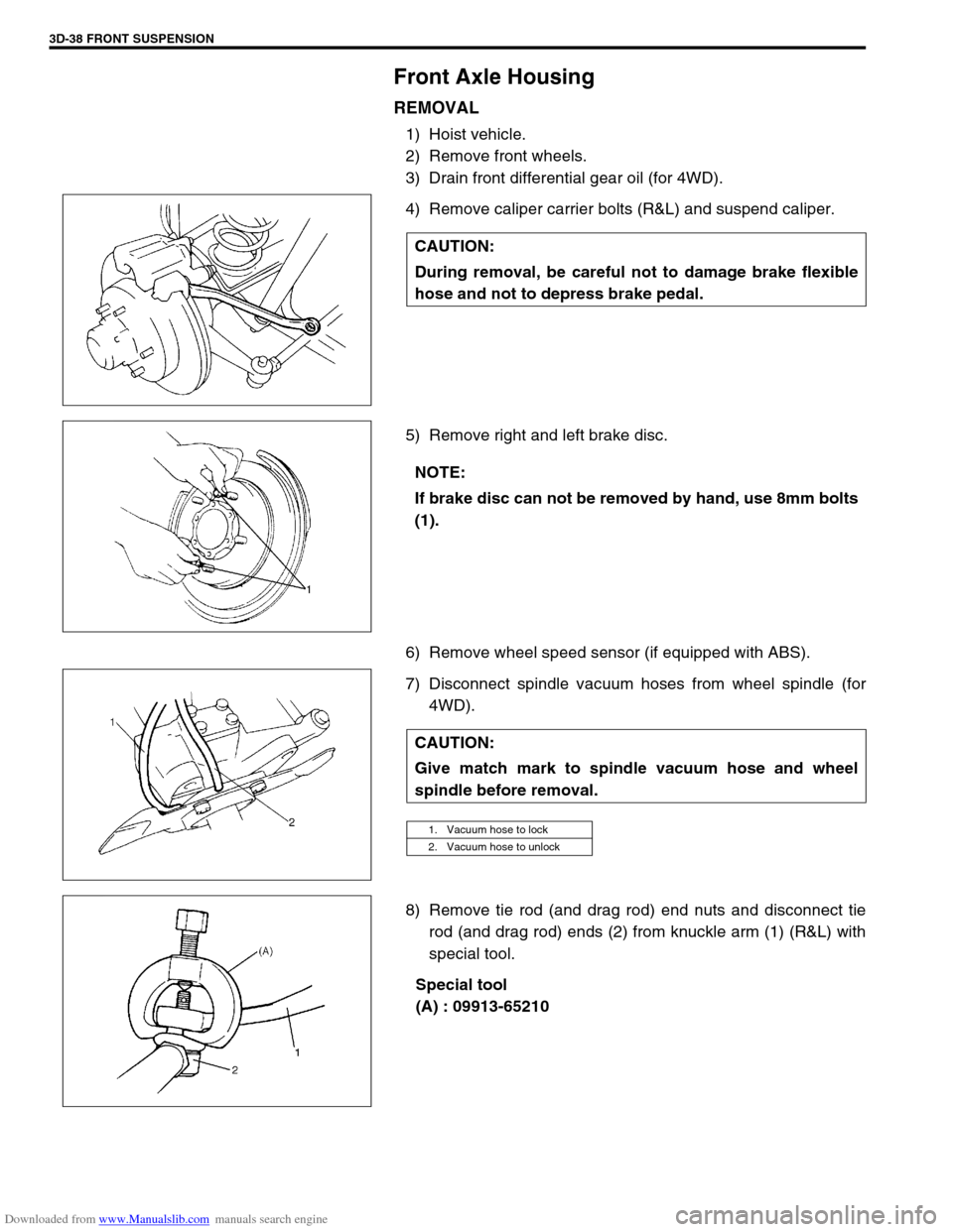
4) Remove caliper carrier bolts (R&L) and suspend caliper.
5) Remove right and left brake disc.
6) Remove wheel speed sensor (if equipped with ABS).
7) Disconnect spindle vacuum hoses from wheel spindle (for
4WD).
8) Remove tie rod (and drag rod) end nuts and disconnect tie
rod (and drag rod) ends (2) from knuckle arm (1) (R&L) with
special tool.
Special tool
(A) : 09913-65210 CAUTION:
During removal, be careful not to damage brake flexible
hose and not to depress brake pedal.
NOTE:
If brake disc can not be removed by hand, use 8mm bolts
(1).
CAUTION:
Give match mark to spindle vacuum hose and wheel
spindle before removal.
1. Vacuum hose to lock
2. Vacuum hose to unlock
Page 229 of 687
Downloaded from www.Manualslib.com manuals search engine 3E-10 REAR SUSPENSION
INSTALLATION
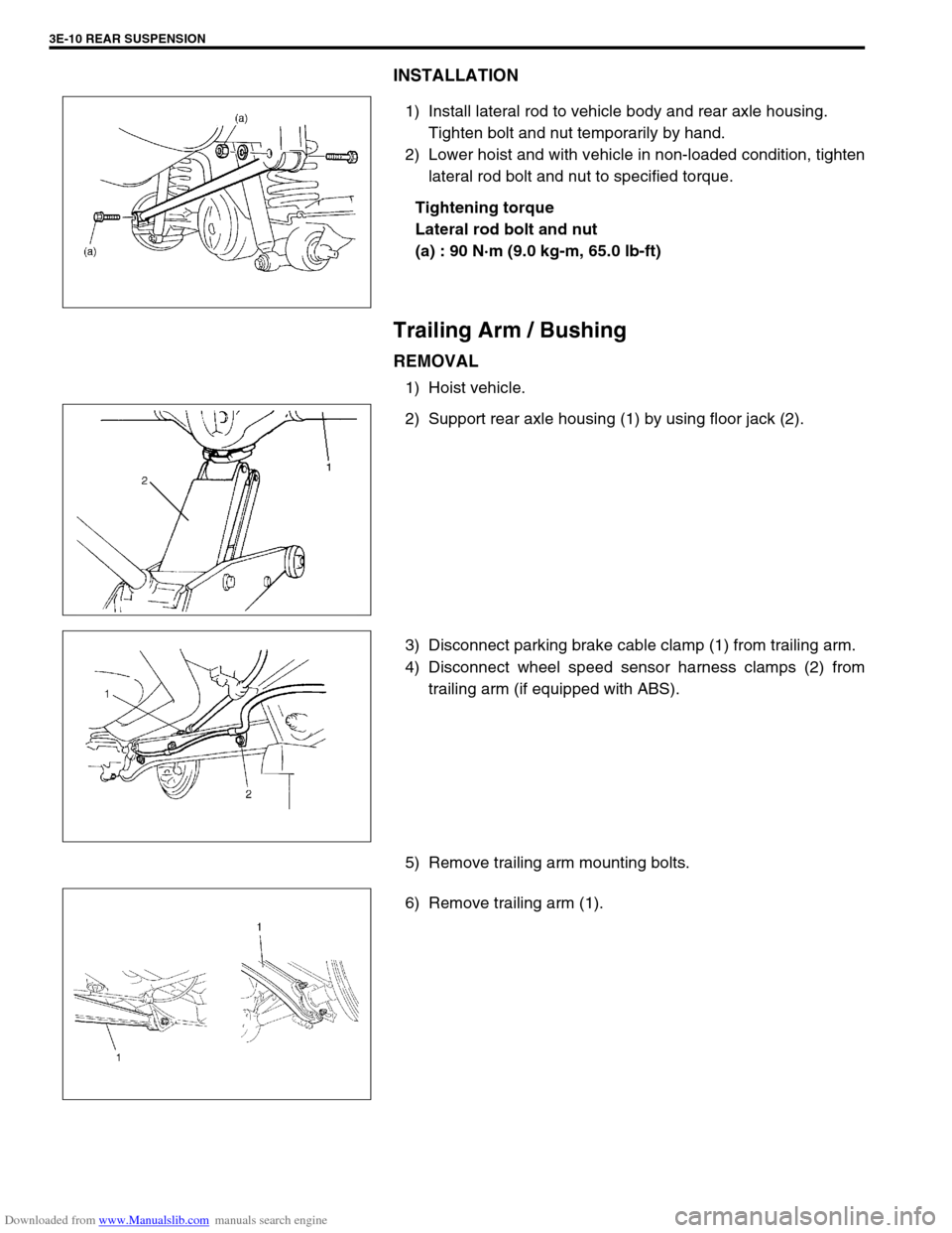
1) Install lateral rod to vehicle body and rear axle housing.
Tighten bolt and nut temporarily by hand.
2) Lower hoist and with vehicle in non-loaded condition, tighten
lateral rod bolt and nut to specified torque.
Tightening torque
Lateral rod bolt and nut
(a) : 90 N·m (9.0 kg-m, 65.0 lb-ft)
Trailing Arm / Bushing
REMOVAL
1) Hoist vehicle.
2) Support rear axle housing (1) by using floor jack (2).
3) Disconnect parking brake cable clamp (1) from trailing arm.
4) Disconnect wheel speed sensor harness clamps (2) from
trailing arm (if equipped with ABS).
5) Remove trailing arm mounting bolts.
6) Remove trailing arm (1).
Page 231 of 687
Downloaded from www.Manualslib.com manuals search engine 3E-12 REAR SUSPENSION
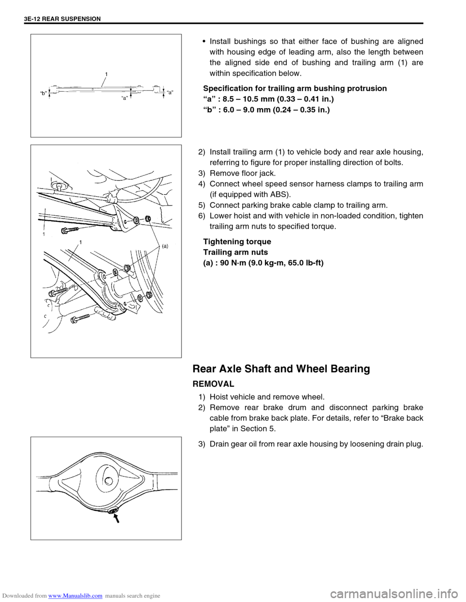
Install bushings so that either face of bushing are aligned
with housing edge of leading arm, also the length between
the aligned side end of bushing and trailing arm (1) are
within specification below.
Specification for trailing arm bushing protrusion
“a” : 8.5 – 10.5 mm (0.33 – 0.41 in.)
“b” : 6.0 – 9.0 mm (0.24 – 0.35 in.)
2) Install trailing arm (1) to vehicle body and rear axle housing,
referring to figure for proper installing direction of bolts.
3) Remove floor jack.
4) Connect wheel speed sensor harness clamps to trailing arm
(if equipped with ABS).
5) Connect parking brake cable clamp to trailing arm.
6) Lower hoist and with vehicle in non-loaded condition, tighten
trailing arm nuts to specified torque.
Tightening torque
Trailing arm nuts
(a) : 90 N·m (9.0 kg-m, 65.0 lb-ft)
Rear Axle Shaft and Wheel Bearing
REMOVAL
1) Hoist vehicle and remove wheel.
2) Remove rear brake drum and disconnect parking brake
cable from brake back plate. For details, refer to “Brake back
plate” in Section 5.
3) Drain gear oil from rear axle housing by loosening drain plug.
Page 232 of 687
Downloaded from www.Manualslib.com manuals search engine REAR SUSPENSION 3E-13
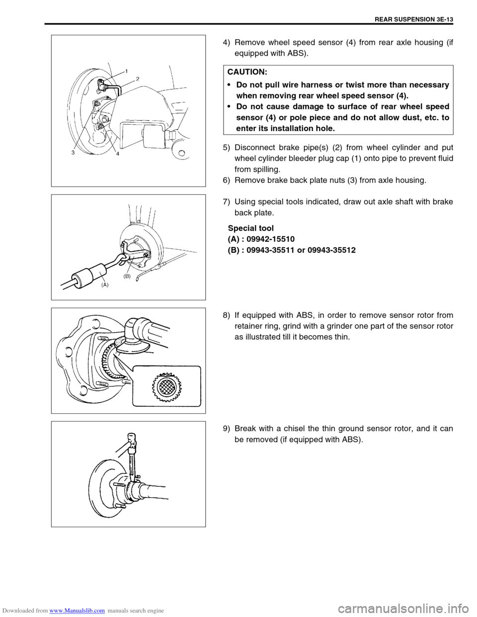
4) Remove wheel speed sensor (4) from rear axle housing (if
equipped with ABS).
5) Disconnect brake pipe(s) (2) from wheel cylinder and put
wheel cylinder bleeder plug cap (1) onto pipe to prevent fluid
from spilling.
6) Remove brake back plate nuts (3) from axle housing.
7) Using special tools indicated, draw out axle shaft with brake
back plate.
Special tool
(A) : 09942-15510
(B) : 09943-35511 or 09943-35512
8) If equipped with ABS, in order to remove sensor rotor from
retainer ring, grind with a grinder one part of the sensor rotor
as illustrated till it becomes thin.
9) Break with a chisel the thin ground sensor rotor, and it can
be removed (if equipped with ABS). CAUTION:
Do not pull wire harness or twist more than necessary
when removing rear wheel speed sensor (4).
Do not cause damage to surface of rear wheel speed
sensor (4) or pole piece and do not allow dust, etc. to
enter its installation hole.
Page 235 of 687
Downloaded from www.Manualslib.com manuals search engine 3E-16 REAR SUSPENSION
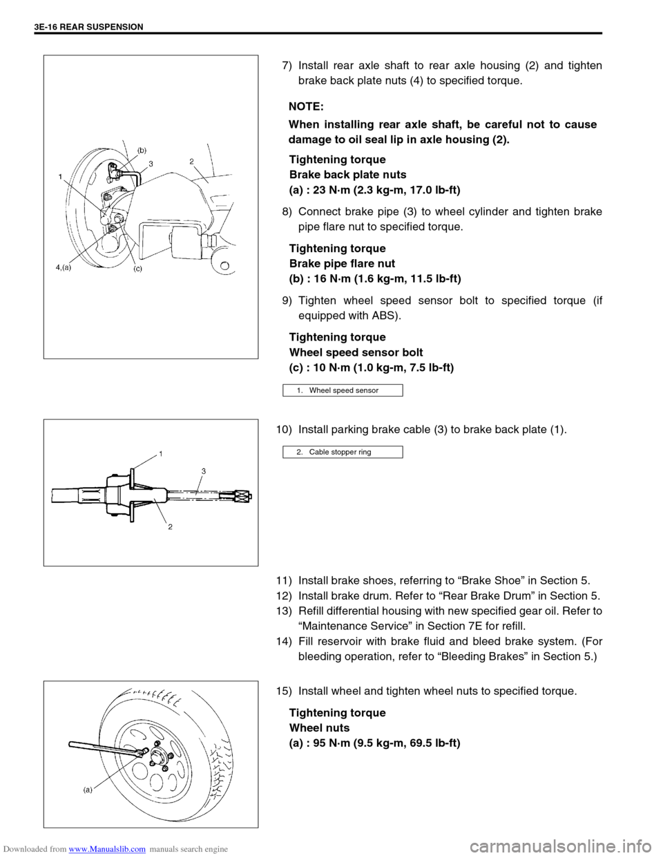
7) Install rear axle shaft to rear axle housing (2) and tighten
brake back plate nuts (4) to specified torque.
Tightening torque
Brake back plate nuts
(a) : 23 N·m (2.3 kg-m, 17.0 lb-ft)
8) Connect brake pipe (3) to wheel cylinder and tighten brake
pipe flare nut to specified torque.
Tightening torque
Brake pipe flare nut
(b) : 16 N·m (1.6 kg-m, 11.5 lb-ft)
9) Tighten wheel speed sensor bolt to specified torque (if
equipped with ABS).
Tightening torque
Wheel speed sensor bolt
(c) : 10 N·m (1.0 kg-m, 7.5 lb-ft)
10) Install parking brake cable (3) to brake back plate (1).
11) Install brake shoes, referring to “Brake Shoe” in Section 5.
12) Install brake drum. Refer to “Rear Brake Drum” in Section 5.
13) Refill differential housing with new specified gear oil. Refer to
“Maintenance Service” in Section 7E for refill.
14) Fill reservoir with brake fluid and bleed brake system. (For
bleeding operation, refer to “Bleeding Brakes” in Section 5.)
15) Install wheel and tighten wheel nuts to specified torque.
Tightening torque
Wheel nuts
(a) : 95 N·m (9.5 kg-m, 69.5 lb-ft) NOTE:
When installing rear axle shaft, be careful not to cause
damage to oil seal lip in axle housing (2).
1. Wheel speed sensor
2. Cable stopper ring
Page 241 of 687

Downloaded from www.Manualslib.com manuals search engine 3E-22 REAR SUSPENSION
Tightening Torque Specifications
Required Service Materials
Fastening portionTightening torque
Nm kg-m lb-ft
Shock absorber upper and lower bolt 85 8.5 61.5
Bump stopper 50 5.0 36.5
Lateral rod bolt and nut
90 9.0 65.0
Trailing arm nut (Front and Rear)
Brake back plate nut 23 2.3 17.0
Brake pipe flare nut 16 1.6 11.5
Rear differential carrier bolt 23 2.3 17.0
Rear propeller shaft bolt (Differential case side) 50 5.0 36.5
Rear propeller shaft bolt (Shaft No.3 transfer case side) 33 3.3 24.0
Wheel nut 95 9.5 69.0
Wheel speed sensor bolt and harness clamp bolt 10 1.0 7.5
MaterialRecommended SUZUKI product
(Part Number)Use
Lithium greaseSUZUKI SUPER GREASE A
(99000-25010)Oil seal lip
SealantSUZUKI BOND NO. 1215
(99000-31110)Joint seam of differential carrier and
axle housing
Water tight sealantSEALING COMPOUND 366E
(99000-31090)To apply to mating surfaces of brake
back plate and rear axle.
Gear oilFor gear oil information, refer to “Mainte-
nance Service” in Section 7E of this manual.Differential gear
(Rear axle housing)