change wheel SUZUKI JIMNY 2005 3.G Service Workshop Manual
[x] Cancel search | Manufacturer: SUZUKI, Model Year: 2005, Model line: JIMNY, Model: SUZUKI JIMNY 2005 3.GPages: 687, PDF Size: 13.38 MB
Page 34 of 687

Downloaded from www.Manualslib.com manuals search engine MAINTENANCE AND LUBRICATION 0B-3
IntervalKm (x 1,000) 153045607590
Miles (x 1,000) 9 18 27 36 45 54
Months 12 24 36 48 60 72
CHASSIS AND BODY
Clutch (pedal height and travel)–I–I–I
Brake discs and pads (thickness, wear, damage) I I I I I I
Brake drums and shoes (wear, damage)–I–I–I
Brake hoses and pipes (leakage, damage, clamp)–I–I–I
Brake fluid–R–R–R
Brake lever and cable (damage, stroke, operation) Inspect at first 15,000 km (9,000 miles) only.
Tires (wear, damage, rotation) I I I I I I
Wheel discs (damage) I I I I I I
Suspension system (tightness, damage, rattle, breakage)–I–I–I
Propeller shafts––I––I
Manual transmission oil (leakage, level) (I: 1st 15,000 km only) I–R––R
Automatic transmission Fluid level–I–I–I
Fluid change Replace every 165,000 km (99,000 miles).
Fluid hose–––R––
Transfer oil (leakage, level) I–I–I–
Differential oil (leakage, level) (R: 1st 15,000 km only) R or I–I–I–
Steering system (tightness, damage, breakage, rattle)–I–I–I
Power steering (if equipped) I I I I I I
All latches, hinges and locks–I–I–I
NOTE:
“R”: Replace or change
“I”: Inspect and correct, replace or lubricate if necessary
Page 35 of 687

Downloaded from www.Manualslib.com manuals search engine 0B-4 MAINTENANCE AND LUBRICATION
Maintenance Recommended Under Severe Driving Conditions
If the vehicle is usually used under the conditions corresponding to any severe condition code given below, it is
recommended that applicable maintenance operation be performed at the particular interval as shown in the fol-
lowing table.
Severe condition code
A : Repeated short trips
B : Driving on rough and/or muddy roads
C : Driving on dusty roads
D : Driving in extremely cold weather and/or salted roads
E : Repeated short trips in extremely cold weather
F : Leaded fuel use
G : – – – – –
H : Trailer towing (if admitted)
Severe
Condition CodeMaintenanceMaintenance
OperationMaintenance Interval
– B C D – – – –Drive belt (V-rib belt)IEvery 15,000 km
(9,000 miles) or 12 months
REvery 45,000 km
(27,000 miles) or 36 months
A – C D E F – H Engine oil and oil filter R Every 5,000 km (3,000 miles) or 4 months
– B – – – – – –Exhaust pipe mountings IEvery 15,000 km
(9,000 miles) or 12 months
– – C – – – – –Air cleaner filter ✱1I Every 2,500 km (1,500 miles)
REvery 30,000 km
(18,000 miles) or 24 months
A B C – E F – H Spark plugsNickel spark plug R Every 10,000 km (6,000 miles) or 8 months
Iridium spark plug
REvery 30,000 km
(18,000 miles) or 24 months
– B C D – – – H Wheel bearing IEvery 15,000 km
(9,000 miles) or 12 months
– B – – – – – –Suspension bolts and nuts TEvery 15,000 km
(9,000 miles) or 12 months
– B – D E – – H Propeller shafts IEvery 15,000 km
(9,000 miles) or 12 months
– B – – E – – HManual transmission,
transfer and differential oilRFirst time only:
15,000 km (9,000 miles) or 12 months
Second time and after: Every 30,000 km
(18,000 miles) or 24 months reckoning from
0 km (0 mile) or 0 month
– B – – E – – H Automatic transmission fluid REvery 30,000 km
(18,000 miles) or 24 months
– B C D – – – –Steering knuckle seal IEvery 15,000 km
(9,000 miles) or 12 months
NOTE:
“I”: Inspect and correct, replace or lubricate if necessary
“R”: Replace or change
“T”: Tighten to the specified torque
✱
✱✱ ✱1: Inspect or replace more frequently if necessary
Page 43 of 687

Downloaded from www.Manualslib.com manuals search engine 0B-12 MAINTENANCE AND LUBRICATION
Brake Drums and Shoes
INSPECTION
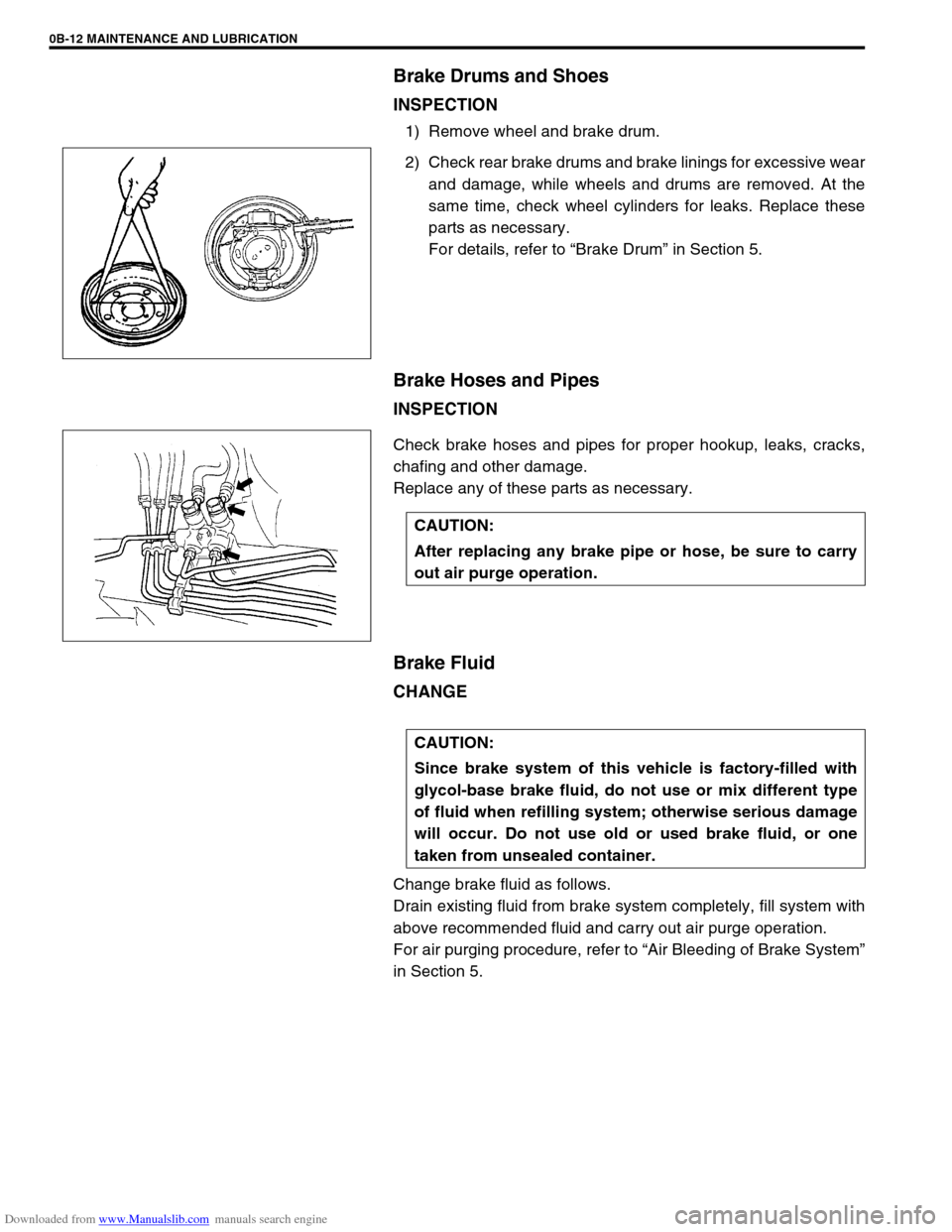
1) Remove wheel and brake drum.
2) Check rear brake drums and brake linings for excessive wear
and damage, while wheels and drums are removed. At the
same time, check wheel cylinders for leaks. Replace these
parts as necessary.
For details, refer to “Brake Drum” in Section 5.
Brake Hoses and Pipes
INSPECTION
Check brake hoses and pipes for proper hookup, leaks, cracks,
chafing and other damage.
Replace any of these parts as necessary.
Brake Fluid
CHANGE
Change brake fluid as follows.
Drain existing fluid from brake system completely, fill system with
above recommended fluid and carry out air purge operation.
For air purging procedure, refer to “Air Bleeding of Brake System”
in Section 5.
CAUTION:
After replacing any brake pipe or hose, be sure to carry
out air purge operation.
CAUTION:
Since brake system of this vehicle is factory-filled with
glycol-base brake fluid, do not use or mix different type
of fluid when refilling system; otherwise serious damage
will occur. Do not use old or used brake fluid, or one
taken from unsealed container.
Page 121 of 687

Downloaded from www.Manualslib.com manuals search engine 3A-4 FRONT WHEEL ALIGNMENT
Camber And Caster Check And Adjustment
Should camber or caster be found out of specifications upon
inspection, locate its cause first. If it is in damaged, loose, bent,
dented or worn suspension parts and axle housing, they should
be replaced. If it is in vehicle body, repair it so as to attain specifi-
cations.
Steering Angle Check And Adjustment
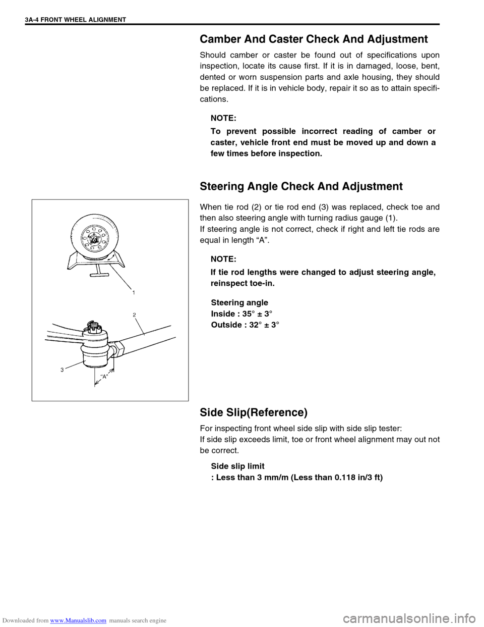
When tie rod (2) or tie rod end (3) was replaced, check toe and
then also steering angle with turning radius gauge (1).
If steering angle is not correct, check if right and left tie rods are
equal in length “A”.
Steering angle
Inside : 35° ± 3°
Outside : 32° ± 3°
Side Slip(Reference)
For inspecting front wheel side slip with side slip tester:
If side slip exceeds limit, toe or front wheel alignment may out not
be correct.
Side slip limit
: Less than 3 mm/m (Less than 0.118 in/3 ft) NOTE:
To prevent possible incorrect reading of camber or
caster, vehicle front end must be moved up and down a
few times before inspection.
NOTE:
If tie rod lengths were changed to adjust steering angle,
reinspect toe-in.
Page 134 of 687

Downloaded from www.Manualslib.com manuals search engine POWER STEERING (P/S) SYSTEM (If equipped) 3B1-3
Diagnosis
Diagnosis Table
Condition Possible Cause Correction
Steering wheel feels
heavy
(at low speed)Fluid deteriorated, low viscosity, different type of
fluid mixedChange fluid.
Pipes or hoses deformed, air entering through
jointCorrect or replace.
Insufficient air bleeding from piping Bleed air.
Belt worn, lacking in tension Adjust belt tension or replace belt
as necessary.
Tire inflation pressure too low Inflate tire.
Wheel alignment out of adjustment Adjust front wheel alignment.
Steering wheel installed improperly (twisted) Install steering wheel correctly.
Hydraulic pressure failing to rise (See NOTE
“A”.)Replace P/S pump.
Slow hydraulic pressure rise (See NOTE “A”.)
Steering wheel feels
heavy momentarily
when turning it to the
left or right.Air drawn in due to insufficient amount of fluid Add fluid and bleed air.
Slipping belt Adjust belt tension or replace belt
as necessary.
No idle-up (See NOTE
“B”.)Defective pressure switch Replace pressure switch
(terminal set).
NOTE:
“A” : Be sure to warm up engine fully before performing this check. Pump vanes are sometimes
hard to come out where temperature is low.
“B” : Acceptable if idling speed does not drop.
Condition Possible Cause Correction
Steering wheel returns
slowly from turns.
(See NOTE “C”.)Dust or foreign object mixed in fluid Change fluid.
Deformed pipes or hoses Correct or replace.
Steering column installed improperly Install correctly.
Wheel alignment maladjusted Adjust.
Linkage or joints not operating smoothly Correct.
Vehicle pulls to one
side during straight
driving.Low or uneven tire inflation pressure Inflate tire (s) as necessary.
Wheel alignment maladjusted Adjust.
Defective spool valve Replace gear box assembly.
Steering wheel play is
large and vehicle wan-
ders.Loose steering shaft nut Retighten.
Loose linkage or joint Retighten.
Loose gear box fixing bolt Retighten.
Front wheel bearing worn Replace.
Fluid leakage
Loose joints of hydraulic pressure pipes and
hosesRetighten.
Deformed or damaged pipes or hoses Correct or replace.
Gear box Replace gear box assembly.
Page 252 of 687

Downloaded from www.Manualslib.com manuals search engine WHEELS AND TIRES 3F-9
Tire
Mounting and demounting
Use tire changing machine to mount or demount tires. Follow equipment manufacturer’s instructions. Do not use
hand tools or tire irons alone to change tires as they may damage tire beads or wheel rim.
Rim bead seats should be cleaned with wire brush or coarse steel wool to remove lubricants, old rubber and
light rust. Before mounting or demounting tire, bead area should be well lubricated with approved tire lubricant.
After mounting, inflate to 240 kPa (35 psi) so that beads are completely seated. Then adjust pressure to speci-
fied shown on tire placard.
Install valve core and inflate to proper pressure.
Repair
There are many different materials and techniques on the market to repair tires. As not all of these work on all
types of tires, tire manufacturers have published detailed instructions on how and when to repair tires. These
instructions can be obtained from the tire manufacturer.WARNING:
Do not stand over tire when inflating. Bead may break when bead snaps over rim’s safety hump and
cause serious personal injury.
Do not exceed 240 kPa (35 psi) pressure when inflating. If 240 kPa (35 psi) pressure will not seat
beads, deflate, re-lubricate and reinflate. Over inflation may cause bead to break and cause serious
personal injury.
Page 488 of 687

Downloaded from www.Manualslib.com manuals search engine ENGINE MECHANICAL (M13 ENGINE) 6A1-7
Oil Pressure Check
Oil level in oil pan.
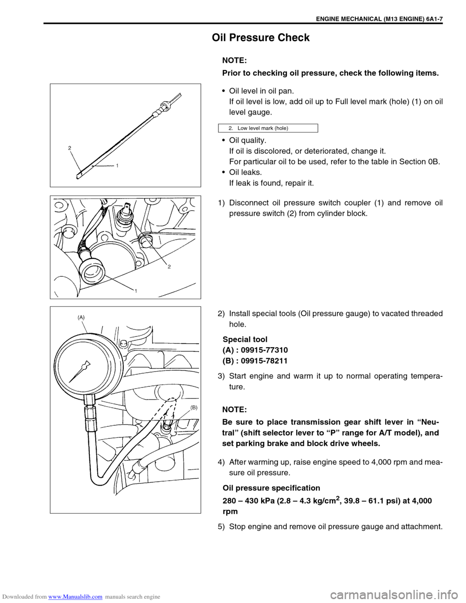
If oil level is low, add oil up to Full level mark (hole) (1) on oil
level gauge.
Oil quality.
If oil is discolored, or deteriorated, change it.
For particular oil to be used, refer to the table in Section 0B.
Oil leaks.
If leak is found, repair it.
1) Disconnect oil pressure switch coupler (1) and remove oil
pressure switch (2) from cylinder block.
2) Install special tools (Oil pressure gauge) to vacated threaded
hole.
Special tool
(A) : 09915-77310
(B) : 09915-78211
3) Start engine and warm it up to normal operating tempera-
ture.
4) After warming up, raise engine speed to 4,000 rpm and mea-
sure oil pressure.
Oil pressure specification
280 – 430 kPa (2.8 – 4.3 kg/cm
2, 39.8 – 61.1 psi) at 4,000
rpm
5) Stop engine and remove oil pressure gauge and attachment.NOTE:
Prior to checking oil pressure, check the following items.
2. Low level mark (hole)
NOTE:
Be sure to place transmission gear shift lever in “Neu-
tral” (shift selector lever to “P” range for A/T model), and
set parking brake and block drive wheels.