coolant level SUZUKI JIMNY 2005 3.G Service Workshop Manual
[x] Cancel search | Manufacturer: SUZUKI, Model Year: 2005, Model line: JIMNY, Model: SUZUKI JIMNY 2005 3.GPages: 687, PDF Size: 13.38 MB
Page 39 of 687
Downloaded from www.Manualslib.com manuals search engine 0B-8 MAINTENANCE AND LUBRICATION
6) Replenish oil until oil level is brought to FULL level mark on
dipstick. (oil pan and oil filter capacity). The filler inlet is at
the top of the cylinder head cover.
It is recommended to use engine oil of SE, SF, SG, SH, SJ or
SL grade.
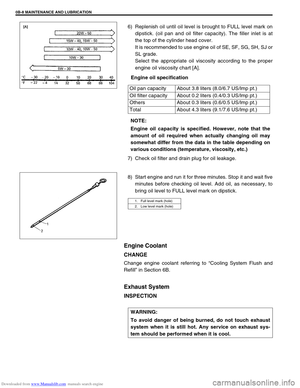
Select the appropriate oil viscosity according to the proper
engine oil viscosity chart [A].
Engine oil specification
7) Check oil filter and drain plug for oil leakage.
8) Start engine and run it for three minutes. Stop it and wait five
minutes before checking oil level. Add oil, as necessary, to
bring oil level to FULL level mark on dipstick.
Engine Coolant
CHANGE
Change engine coolant referring to “Cooling System Flush and
Refill” in Section 6B.
Exhaust System
INSPECTION
Oil pan capacity About 3.8 liters (8.0/6.7 US/lmp pt.)
Oil filter capacity About 0.2 liters (0.4/0.3 US/lmp pt.)
Others About 0.3 liters (0.6/0.5 US/lmp pt.)
Total About 4.3 liters (9.1/7.6 US/lmp pt.)
NOTE:
Engine oil capacity is specified. However, note that the
amount of oil required when actually changing oil may
somewhat differ from the data in the table depending on
various conditions (temperature, viscosity, etc.)
1. Full level mark (hole)
2. Low level mark (hole)
WARNING:
To avoid danger of being burned, do not touch exhaust
system when it is still hot. Any service on exhaust sys-
tem should be performed when it is cool.
Page 373 of 687

Downloaded from www.Manualslib.com manuals search engine 6-16 ENGINE GENERAL INFORMATION AND DIAGNOSIS
Diagnostic trouble code (DTC) table
DTC
NO.DETECTING ITEM DETECTING CONDITION
(DTC will set when detecting :)MIL
(vehicle
with immo-
bilizer indi-
cator lamp)MIL
(vehicle
without
immobi-
lizer indica-
tor lamp)
P0105
(No.11)Manifold absolute pressure
circuit malfunctionLow pressure-high vacuum-low voltage
(or MAP sensor circuit shorted to ground)
High pressure-low vacuum-high voltage
(or MAP sensor circuit open)1 driving
cycle1 driving
cycle
P0110
(No.18)Intake air temp. circuit mal-
functionIntake air temp. circuit low input
Intake air temp. circuit high input1 driving
cycle1 driving
cycle
P0115
(No.19)Engine coolant temp. cir-
cuit malfunctionEngine coolant temp. circuit low input
Engine coolant temp. circuit high input1 driving
cycle1 driving
cycle
P0120
(No.13)Throttle position circuit mal-
functionThrottle position circuit low input
Throttle position circuit high input1 driving
cycle1 driving
cycle
P0121Throttle position circuit per-
formance problemPoor performance of TP sensor 2 driving
cyclesNot
applicable
P0130
(No.14)HO2S circuit malfunction
(Sensor-1)Min. output voltage of HO2S-higher than
specification
Max. output voltage of HO2S-lower than
specification2 driving
cycles1 driving
cycle
P0133HO2S circuit slow response
(Sensor-1)Response time of HO2S-1 output voltage
between rich and lean is longer than spec-
ification.2 driving
cyclesNot
applicable
P0135
(No.14)HO2S heater circuit mal-
function (Sensor-1)Terminal voltage is lower than specification
at heater OFF or it is higher at heater ON.2 driving
cycles1 driving
cycle
P0136HO2S circuit malfunction
(Sensor-2)HO2S-2 voltage is higher than specifica-
tion2 driving
cyclesNot
applicable
P0141HO2S heater circuit mal-
function (Sensor-2)Terminal voltage is lower than specification
at heater OFF or it is higher at heater ON.
(or heater circuit or short)2 driving
cyclesNot
applicable
P0171 Fuel system too leanShort term fuel trim or total fuel trim (short
and long terms added) is larger than spec-
ification for specified time or longer.
(fuel trim toward rich side is large.)2 driving
cyclesNot
applicable
P0172 Fuel system too richShort term fuel trim or total fuel trim (short
and long term added) is smaller than spec-
ification for specified time or longer.
(fuel trim toward lean side is large.)2 driving
cyclesNot
applicable
P0300
P0301
P0302
P0303
P0304Random misfire detected
Cylinder 1 misfire detected
Cylinder 2 misfire detected
Cylinder 3 misfire detected
Cylinder 4 misfire detectedMisfire of such level as to cause damage
to three way catalystMIL flashing
during mis-
fire detec-
tionNot
applicable
Misfire of such level as to deteriorate emis-
sion but not to cause damage to three way
catalyst2 driving
cyclesNot
applicable
P0325
(No.17)Knock sensor circuit mal-
functionKnock sensor circuit low input
Knock sensor circuit high input1 driving
cycle1 driving
cycle
Page 377 of 687

Downloaded from www.Manualslib.com manuals search engine 6-20 ENGINE GENERAL INFORMATION AND DIAGNOSIS
Visual inspection
Visually check following parts and systems.
INSPECTION ITEM REFERRING SECTION
Engine oil – level, leakage Section 0B
Engine coolant – level, leakage Section 0B
Fuel – level, leakage Section 0B
A/T fluid – level, leakage Section 0B
Air cleaner element – dirt, clogging Section 0B
Battery – fluid level, corrosion of terminal
Water pump belt – tension, damage Section 0B
Throttle cable – play, installation
Section 6E Vacuum hoses of air intake system – disconnection, looseness,
deterioration, bend
Connectors of electric wire harness – disconnection, friction
Fuses – burning Section 8
Parts – installation, bolt – looseness
Parts – deformation
Other parts that can be checked visually
Also check following items at engine start, if possible
Malfunction indicator lamp – operation Section 6
Charge warning lamp – operation Section 6H
Engine oil pressure warning lamp – operation Section 8 (Section 6 for pressure check)
Engine coolant temp. meter – operation Section 8
Fuel level meter – operation Section 8
Tachometer, if equipped – operation
Abnormal air being inhaled from air intake system
Exhaust system – leakage of exhaust gas, noise
Other parts that can be checked visually
Page 414 of 687

Downloaded from www.Manualslib.com manuals search engine ENGINE GENERAL INFORMATION AND DIAGNOSIS 6-57
DTC P0121 Throttle Position Circuit Range / Performance Problem
WIRING DIAGRAM
Refer to DTC P0120 section.
CIRCUIT DESCRIPTION
DTC CONFIRMATION PROCEDURE
1) Turn ignition switch OFF. Clear DTC with ignition switch ON, check vehicle and environmental condition for :
–Altitude (barometric pressure) : 2400 m, 8000 ft or less (560 mmHg, 75 kPa or more)
–Ambient temp. : –10 °C, 14 °F or higher
–Intake air temp. : 70 °C, 158 °F or lower
–Engine coolant temp. : 70 °C, 158 °F or higher
2) Warm up engine to normal operating temperature.
3) Increase vehicle speed to 30 – 40 mph, 50 – 60 km/h in 3rd gear or “D” range and hold throttle valve at that
opening position for 1 min.
4) Stop vehicle.
5) Check DTC in “DTC” mode and pending DTC in “ON BOARD TEST” or “PENDING DTC” mode.
INSPECTION
DTC DETECTING CONDITION POSSIBLE CAUSE
After engine warmed up.
Difference between actual throttle opening (detected from TP sensor)
and opening calculated by ECM (Obtained on the basis of engine
speed and intake manifold pressure) in larger than specified value.
✱2 driving cycle detection logic, continuous monitoringTP sensor malfunction
High resistance in the circuit
ECM malfunction
WARNING:
When performing a road test, select a place where there is no traffic or possibility of a traffic acci-
dent and be very careful during testing to avoid occurrence of an accident.
Road test should be carried out with 2 persons, a driver and a tester, on a level road.
Step Action Yes No
1Was “Engine Diag. Flow Table” performed? Go to Step 2. Go to “Engine Diag. Flow
Table”.
2 Is SUZUKI scan tool available? Go to Step 3. Go to Step 4.
3 Check TP Sensor and Its Circuit.
1) Turn ignition switch OFF and connect
SUZUKI scan tool to DLC. See Fig. 1.
2) Turn ignition switch ON and check TP sen-
sor output voltage when throttle valve is at
idle position and fully opened. See Fig. 3.
Dose voltage vary within specified value linearly
as shown in figure?Substitute a known-good
ECM and recheck.Go to Step 5.
Page 446 of 687
Downloaded from www.Manualslib.com manuals search engine ENGINE GENERAL INFORMATION AND DIAGNOSIS 6-89
DTC CONFIRMATION PROCEDURE
1) Turn ignition switch OFF.
Clear DTC with ignition switch ON, check vehicle and environmental condition for :
–Altitude (barometric pressure) : 2400 m, 8000 ft or less (560 mmHg, 75 kPa or more)
–Ambient temp. : –10 °C, 14 °F or higher
–Intake air temp. : 70 °C, 158 °F or lower
–Engine coolant temp. : 70 – 110 °C, 158 – 230 °F
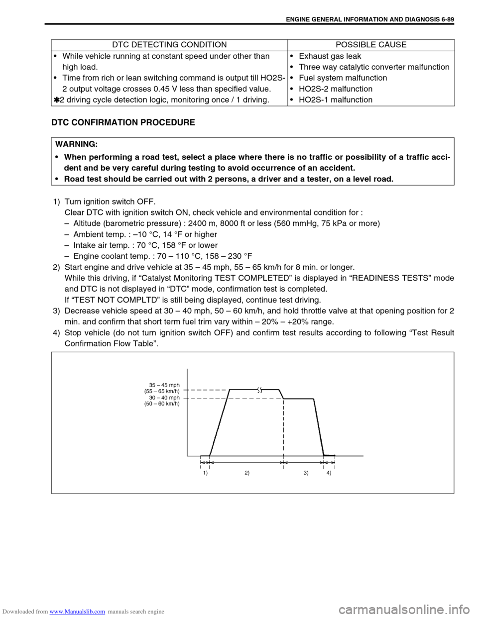
2) Start engine and drive vehicle at 35 – 45 mph, 55 – 65 km/h for 8 min. or longer.
While this driving, if “Catalyst Monitoring TEST COMPLETED” is displayed in “READINESS TESTS” mode
and DTC is not displayed in “DTC” mode, confirmation test is completed.
If “TEST NOT COMPLTD” is still being displayed, continue test driving.
3) Decrease vehicle speed at 30 – 40 mph, 50 – 60 km/h, and hold throttle valve at that opening position for 2
min. and confirm that short term fuel trim vary within – 20% – +20% range.
4) Stop vehicle (do not turn ignition switch OFF) and confirm test results according to following “Test Result
Confirmation Flow Table”. DTC DETECTING CONDITION POSSIBLE CAUSE
While vehicle running at constant speed under other than
high load.
Time from rich or lean switching command is output till HO2S-
2 output voltage crosses 0.45 V less than specified value.
✱
✱✱ ✱2 driving cycle detection logic, monitoring once / 1 driving.Exhaust gas leak
Three way catalytic converter malfunction
Fuel system malfunction
HO2S-2 malfunction
HO2S-1 malfunction
WARNING:
When performing a road test, select a place where there is no traffic or possibility of a traffic acci-
dent and be very careful during testing to avoid occurrence of an accident.
Road test should be carried out with 2 persons, a driver and a tester, on a level road.
Page 578 of 687

Downloaded from www.Manualslib.com manuals search engine ENGINE COOLING 6B-1
6B
SECTION 6B
ENGINE COOLING
CONTENTS
General Description ........................................6B-2
Cooling System Circulation ........................... 6B-2
Radiator Cap ................................................. 6B-3
Coolant Reservoir ......................................... 6B-3
Water Pump .................................................. 6B-4
Thermostat .................................................... 6B-4
Cooling Fan Clutch ........................................ 6B-4
Coolant (Water) Temperature Gauge............ 6B-4
Diagnosis .........................................................6B-5
Maintenance ....................................................6B-6
Coolant .......................................................... 6B-6
Coolant Level ................................................ 6B-7
Cooling System Service ................................ 6B-7Cooling System Flush and Refill ................... 6B-8
Water Pump Belt Tension ............................. 6B-9
On-Vehicle Service ....................................... 6B-10
Cooling System Component ....................... 6B-10
Coolant Draining ......................................... 6B-11
Cooling Water Pipes or Hoses .................... 6B-11
Thermostat .................................................. 6B-11
Water Pump Belt and Cooling Fan ............. 6B-13
Radiator ...................................................... 6B-14
Water Pump ................................................ 6B-15
Required Service Material ............................ 6B-17
Tightening Torque Specification ................. 6B-17
Page 580 of 687
Downloaded from www.Manualslib.com manuals search engine ENGINE COOLING 6B-3
Radiator Cap
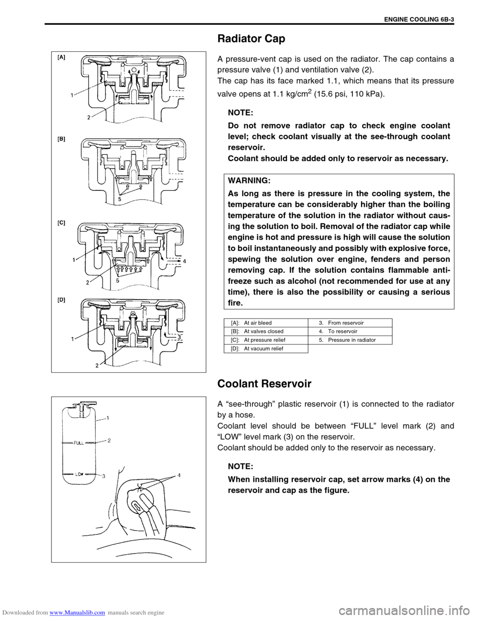
A pressure-vent cap is used on the radiator. The cap contains a
pressure valve (1) and ventilation valve (2).
The cap has its face marked 1.1, which means that its pressure
valve opens at 1.1 kg/cm
2 (15.6 psi, 110 kPa).
Coolant Reservoir
A “see-through” plastic reservoir (1) is connected to the radiator
by a hose.
Coolant level should be between “FULL” level mark (2) and
“LOW” level mark (3) on the reservoir.
Coolant should be added only to the reservoir as necessary.NOTE:
Do not remove radiator cap to check engine coolant
level; check coolant visually at the see-through coolant
reservoir.
Coolant should be added only to reservoir as necessary.
WARNING:
As long as there is pressure in the cooling system, the
temperature can be considerably higher than the boiling
temperature of the solution in the radiator without caus-
ing the solution to boil. Removal of the radiator cap while
engine is hot and pressure is high will cause the solution
to boil instantaneously and possibly with explosive force,
spewing the solution over engine, fenders and person
removing cap. If the solution contains flammable anti-
freeze such as alcohol (not recommended for use at any
time), there is also the possibility or causing a serious
fire.
[A]: At air bleed 3. From reservoir
[B]: At valves closed 4. To reservoir
[C]: At pressure relief 5. Pressure in radiator
[D]: At vacuum relief
NOTE:
When installing reservoir cap, set arrow marks (4) on the
reservoir and cap as the figure.
Page 582 of 687

Downloaded from www.Manualslib.com manuals search engine ENGINE COOLING 6B-5
Diagnosis
Condition Possible Cause Correction
Engine overheats
Loose or broken water pump belt
Not enough coolant
Faulty thermostat
Faulty water pump
Dirty or bent radiator fins
Coolant leakage on cooling system
Defective cooling fan clutch
Plugged radiator
Faulty radiator cap
Maladjusted ignition timing
Dragging brakes
Slipping clutchAdjust or replace.
Check coolant level and add as
necessary.
Replace.
Replace.
Clean or remedy.
Repair.
Check and replace as necessary.
Check and replace radiator as
necessary.
Replace.
Check system related parts.
Adjust brake.
Adjust or replace.
Page 584 of 687
Downloaded from www.Manualslib.com manuals search engine ENGINE COOLING 6B-7
Coolant Level
To check level, look at “see-through” reservoir.
It is not necessary to remove radiator cap to check coolant level.
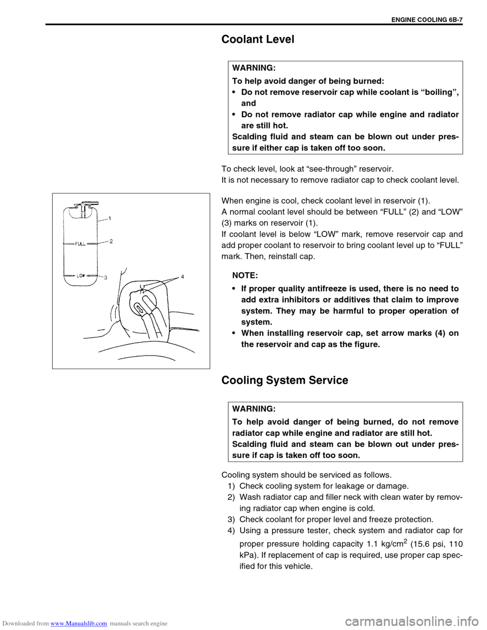
When engine is cool, check coolant level in reservoir (1).
A normal coolant level should be between “FULL” (2) and “LOW”
(3) marks on reservoir (1).
If coolant level is below “LOW” mark, remove reservoir cap and
add proper coolant to reservoir to bring coolant level up to “FULL”
mark. Then, reinstall cap.
Cooling System Service
Cooling system should be serviced as follows.
1) Check cooling system for leakage or damage.
2) Wash radiator cap and filler neck with clean water by remov-
ing radiator cap when engine is cold.
3) Check coolant for proper level and freeze protection.
4) Using a pressure tester, check system and radiator cap for
proper pressure holding capacity 1.1 kg/cm
2 (15.6 psi, 110
kPa). If replacement of cap is required, use proper cap spec-
ified for this vehicle. WARNING:
To help avoid danger of being burned:
Do not remove reservoir cap while coolant is “boiling”,
and
Do not remove radiator cap while engine and radiator
are still hot.
Scalding fluid and steam can be blown out under pres-
sure if either cap is taken off too soon.
NOTE:
If proper quality antifreeze is used, there is no need to
add extra inhibitors or additives that claim to improve
system. They may be harmful to proper operation of
system.
When installing reservoir cap, set arrow marks (4) on
the reservoir and cap as the figure.
WARNING:
To help avoid danger of being burned, do not remove
radiator cap while engine and radiator are still hot.
Scalding fluid and steam can be blown out under pres-
sure if cap is taken off too soon.
Page 585 of 687
Downloaded from www.Manualslib.com manuals search engine 6B-8 ENGINE COOLING
5) Tighten hose clamps and inspect all hoses.
Replace hoses whenever cracked, swollen or otherwise
deteriorated.
6) Clean frontal area of radiator core.
Cooling System Flush and Refill
1) Remove radiator cap when engine is cool:
Turn cap slowly to the left until it reaches a “stop” (Do not
press down while turning it).
Wait until pressure is relieved (indicated by a hissing sound)
then press down on cap and continue to turn it to the left.
2) With radiator cap removed, run engine until upper radiator
hose is hot (this shows that thermostat is open and coolant is
flowing through system).
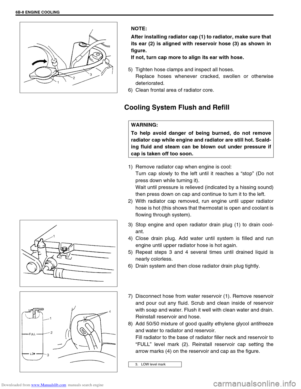
3) Stop engine and open radiator drain plug (1) to drain cool-
ant.
4) Close drain plug. Add water until system is filled and run
engine until upper radiator hose is hot again.
5) Repeat steps 3 and 4 several times until drained liquid is
nearly colorless.
6) Drain system and then close radiator drain plug tightly.
7) Disconnect hose from water reservoir (1). Remove reservoir
and pour out any fluid. Scrub and clean inside of reservoir
with soap and water. Flush it well with clean water and drain.
Reinstall reservoir and hose.
8) Add 50/50 mixture of good quality ethylene glycol antifreeze
and water to radiator and reservoir.
Fill radiator to the base of radiator filler neck and reservoir to
“FULL” level mark (2). Reinstall reservoir cap setting the
arrow marks (4) on the reservoir and cap as the figure. NOTE:
After installing radiator cap (1) to radiator, make sure that
its ear (2) is aligned with reservoir hose (3) as shown in
figure.
If not, turn cap more to align its ear with hose.
WARNING:
To help avoid danger of being burned, do not remove
radiator cap while engine and radiator are still hot. Scald-
ing fluid and steam can be blown out under pressure if
cap is taken off too soon.
3. LOW level mark