head gasket removal SUZUKI JIMNY 2005 3.G Service Workshop Manual
[x] Cancel search | Manufacturer: SUZUKI, Model Year: 2005, Model line: JIMNY, Model: SUZUKI JIMNY 2005 3.GPages: 687, PDF Size: 13.38 MB
Page 496 of 687

Downloaded from www.Manualslib.com manuals search engine ENGINE MECHANICAL (M13 ENGINE) 6A1-15
Cylinder Head Cover
REMOVAL
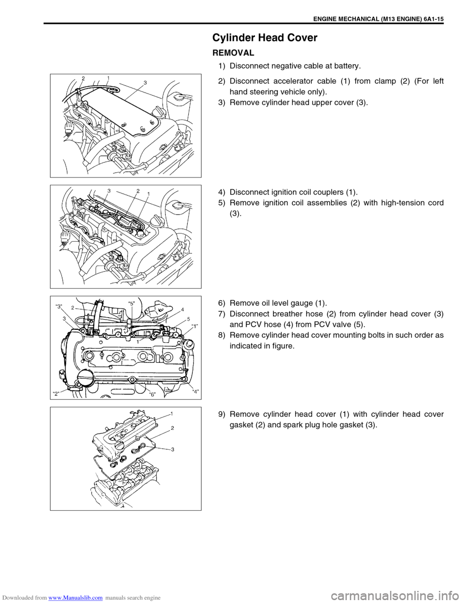
1) Disconnect negative cable at battery.
2) Disconnect accelerator cable (1) from clamp (2) (For left
hand steering vehicle only).
3) Remove cylinder head upper cover (3).
4) Disconnect ignition coil couplers (1).
5) Remove ignition coil assemblies (2) with high-tension cord
(3).
6) Remove oil level gauge (1).
7) Disconnect breather hose (2) from cylinder head cover (3)
and PCV hose (4) from PCV valve (5).
8) Remove cylinder head cover mounting bolts in such order as
indicated in figure.
9) Remove cylinder head cover (1) with cylinder head cover
gasket (2) and spark plug hole gasket (3).
Page 501 of 687

Downloaded from www.Manualslib.com manuals search engine 6A1-20 ENGINE MECHANICAL (M13 ENGINE)
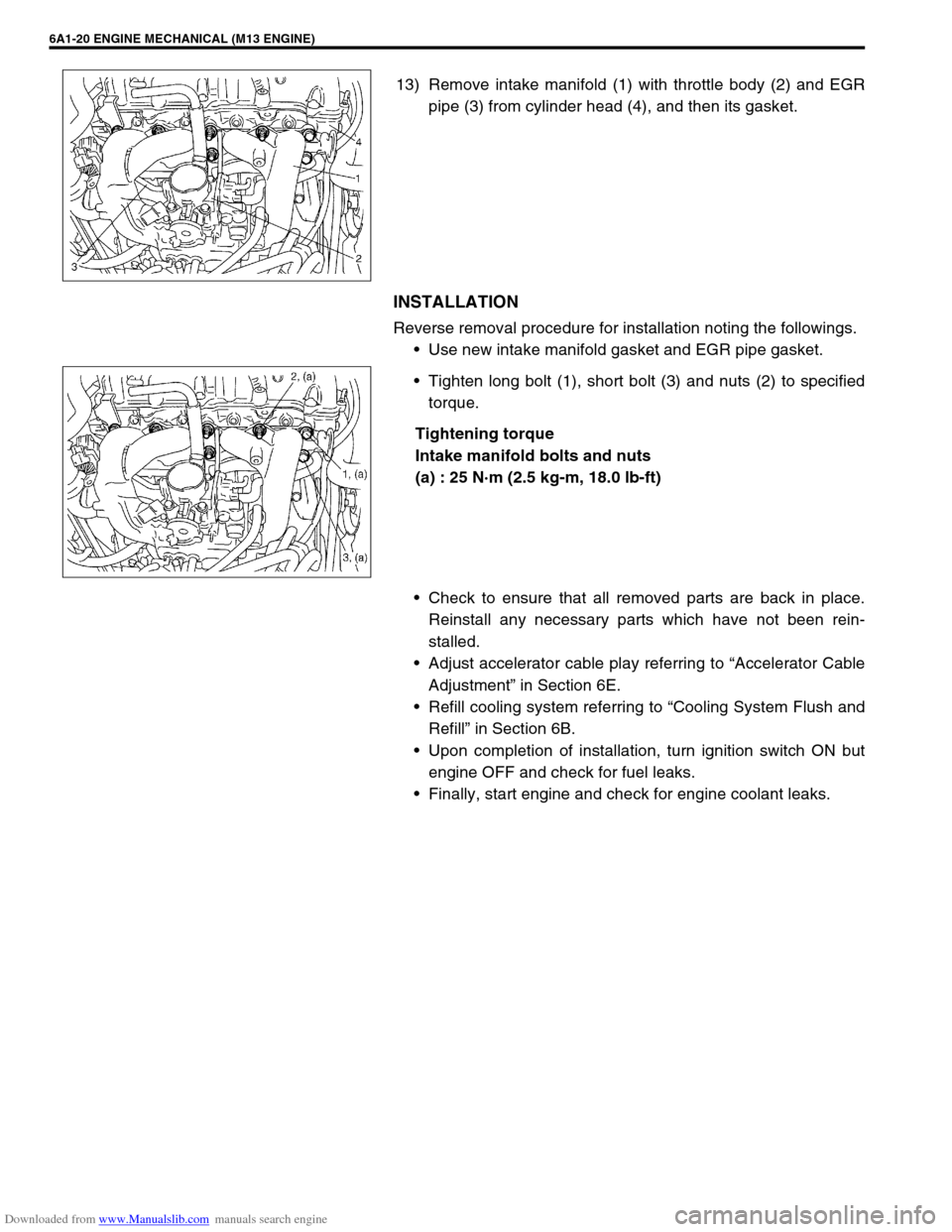
13) Remove intake manifold (1) with throttle body (2) and EGR
pipe (3) from cylinder head (4), and then its gasket.
INSTALLATION
Reverse removal procedure for installation noting the followings.
Use new intake manifold gasket and EGR pipe gasket.
Tighten long bolt (1), short bolt (3) and nuts (2) to specified
torque.
Tightening torque
Intake manifold bolts and nuts
(a) : 25 N·m (2.5 kg-m, 18.0 lb-ft)
Check to ensure that all removed parts are back in place.
Reinstall any necessary parts which have not been rein-
stalled.
Adjust accelerator cable play referring to “Accelerator Cable
Adjustment” in Section 6E.
Refill cooling system referring to “Cooling System Flush and
Refill” in Section 6B.
Upon completion of installation, turn ignition switch ON but
engine OFF and check for fuel leaks.
Finally, start engine and check for engine coolant leaks.
Page 509 of 687

Downloaded from www.Manualslib.com manuals search engine 6A1-28 ENGINE MECHANICAL (M13 ENGINE)
Timing Chain Cover
REMOVAL
1) Disconnect negative cable at battery.
2) Remove A/C compressor and/or P/S pump belt (if
equipped).
3) Remove generator belt.
4) Drain engine oil.
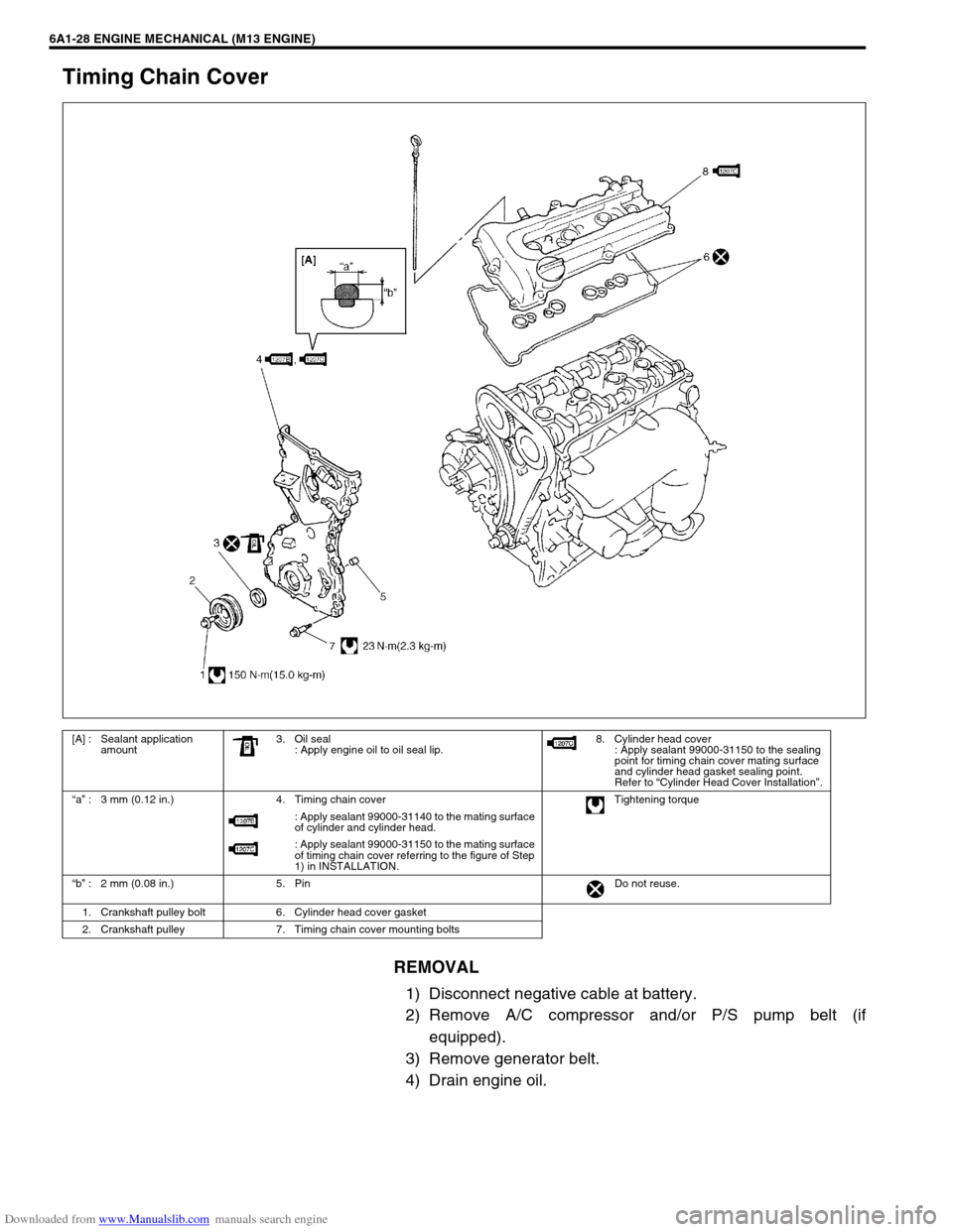
[A] : Sealant application
amount3. Oil seal
: Apply engine oil to oil seal lip.8. Cylinder head cover
: Apply sealant 99000-31150 to the sealing
point for timing chain cover mating surface
and cylinder head gasket sealing point.
Refer to “Cylinder Head Cover Installation”.
“a” : 3 mm (0.12 in.) 4. Timing chain cover Tightening torque
: Apply sealant 99000-31140 to the mating surface
of cylinder and cylinder head.
: Apply sealant 99000-31150 to the mating surface
of timing chain cover referring to the figure of Step
1) in INSTALLATION.
“b” : 2 mm (0.08 in.) 5. Pin Do not reuse.
1. Crankshaft pulley bolt 6. Cylinder head cover gasket
2. Crankshaft pulley 7. Timing chain cover mounting bolts
Page 644 of 687

Downloaded from www.Manualslib.com manuals search engine ENGINE AND EMISSION CONTROL SYSTEM 6E-39
REMOVAL
1) Disconnect negative cable at battery.
2) Disconnect EGR valve connector.
3) Remove EGR pipe.
4) Remove EGR valve and gasket from cylinder head.
INSPECTION
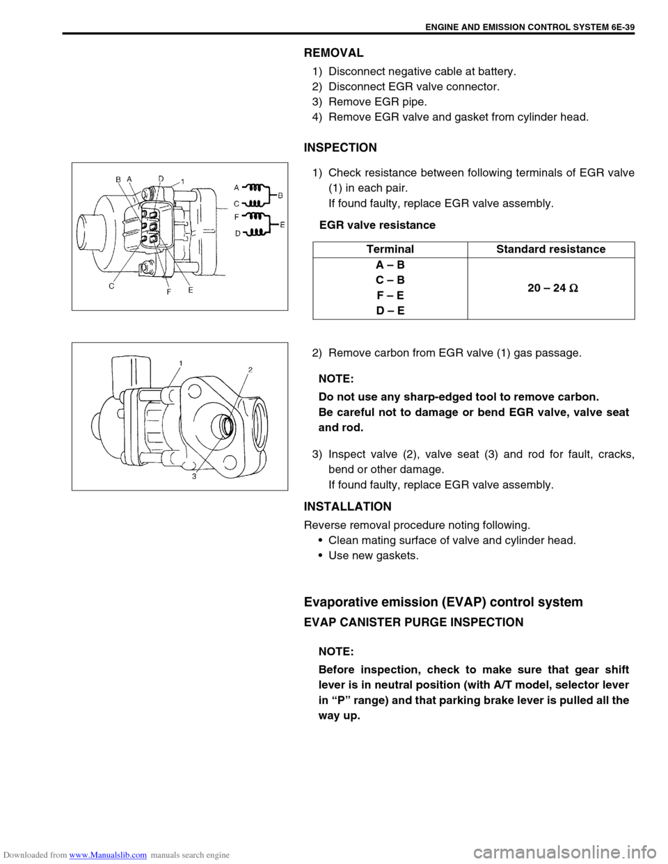
1) Check resistance between following terminals of EGR valve
(1) in each pair.
If found faulty, replace EGR valve assembly.
EGR valve resistance
2) Remove carbon from EGR valve (1) gas passage.
3) Inspect valve (2), valve seat (3) and rod for fault, cracks,
bend or other damage.
If found faulty, replace EGR valve assembly.
INSTALLATION
Reverse removal procedure noting following.
Clean mating surface of valve and cylinder head.
Use new gaskets.
Evaporative emission (EVAP) control system
EVAP CANISTER PURGE INSPECTION
Terminal Standard resistance
A – B
C – B
F – E
D – E 20 – 24
Ω
ΩΩ Ω
NOTE:
Do not use any sharp-edged tool to remove carbon.
Be careful not to damage or bend EGR valve, valve seat
and rod.
NOTE:
Before inspection, check to make sure that gear shift
lever is in neutral position (with A/T model, selector lever
in “P” range) and that parking brake lever is pulled all the
way up.