key SUZUKI JIMNY 2005 3.G Service Workshop Manual
[x] Cancel search | Manufacturer: SUZUKI, Model Year: 2005, Model line: JIMNY, Model: SUZUKI JIMNY 2005 3.GPages: 687, PDF Size: 13.38 MB
Page 53 of 687

Downloaded from www.Manualslib.com manuals search engine 0B-22 MAINTENANCE AND LUBRICATION
Recommended Fluids and Lubricants
Engine oilSE, SF, SG, SH, SJ or SL
(Refer to “Engine Oil and Oil Filter” in this section for engine oil viscos-
ity.)
Engine coolant
(Ethylene glycol base coolant)“Antifreeze/Anticorrosion coolant”
Brake fluid DOT 3
Manual transmission oil Refer to “Maintenance Service” in Section 7A.
Transfer oil Refer to “Oil Change” in Section 7D.
Differential oil (front & rear) Refer to “Oil Change” in Section 7E and 7F.
Automatic transmission fluid
An equivalent of DEXRON
®-IIE or DEXRON®-III
Power steering fluid
An equivalent of DEXRON
®-II, DEXRON®-IIE or DEXRON®-III
Clutch linkage pivot points
Water resistance chassis grease
(SUZUKI SUPER GREASE A 99000-25010)
Steering knuckle seal
Door hinges
Engine oil or water resistance chassis grease
Hood latch assembly
Key lock cylinder Spray lubricant
Page 165 of 687
Downloaded from www.Manualslib.com manuals search engine 3C-12 STEERING WHEEL AND COLUMN
REMOVAL
1) Disconnect negative battery cable at battery terminal.
2) For vehicle equipped with air bag system, disable air bag
system referring to “Disabling Air Bag System” in Section
10B.
3) If necessary, remove steering wheel and combination switch
assembly referring to “Steering Wheel” and “Combination
switch/Contact Coil and Combination Switch Assembly” in
this section.
If not removing steering wheel and/or combination switch
assembly, perform the following procedure.
a) Turn steering wheel so that vehicle’s front tires are at
straight ahead position.
b) Turn ignition switch to “LOCK” position and remove key.
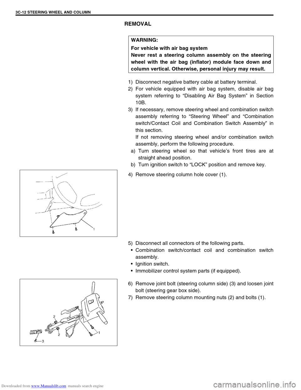
4) Remove steering column hole cover (1).
5) Disconnect all connectors of the following parts.
Combination switch/contact coil and combination switch
assembly.
Ignition switch.
Immobilizer control system parts (if equipped).
6) Remove joint bolt (steering column side) (3) and loosen joint
bolt (steering gear box side).
7) Remove steering column mounting nuts (2) and bolts (1).WARNING:
For vehicle with air bag system
Never rest a steering column assembly on the steering
wheel with the air bag (inflator) module face down and
column vertical. Otherwise, personal injury may result.
Page 166 of 687
Downloaded from www.Manualslib.com manuals search engine STEERING WHEEL AND COLUMN 3C-13
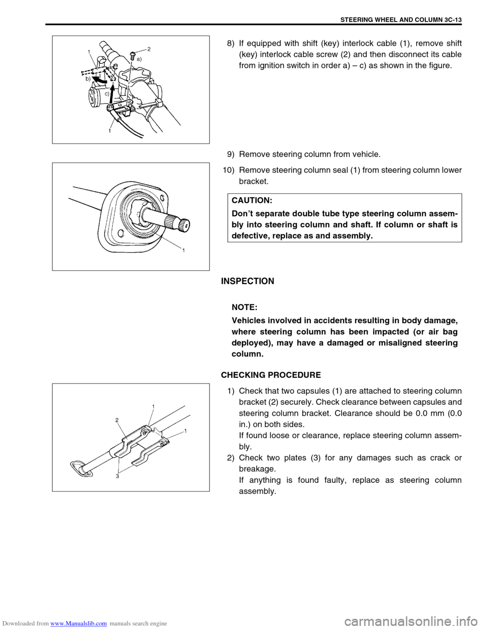
8) If equipped with shift (key) interlock cable (1), remove shift
(key) interlock cable screw (2) and then disconnect its cable
from ignition switch in order a) – c) as shown in the figure.
9) Remove steering column from vehicle.
10) Remove steering column seal (1) from steering column lower
bracket.
INSPECTION
CHECKING PROCEDURE
1) Check that two capsules (1) are attached to steering column
bracket (2) securely. Check clearance between capsules and
steering column bracket. Clearance should be 0.0 mm (0.0
in.) on both sides.
If found loose or clearance, replace steering column assem-
bly.
2) Check two plates (3) for any damages such as crack or
breakage.
If anything is found faulty, replace as steering column
assembly.
CAUTION:
Don’t separate double tube type steering column assem-
bly into steering column and shaft. If column or shaft is
defective, replace as and assembly.
NOTE:
Vehicles involved in accidents resulting in body damage,
where steering column has been impacted (or air bag
deployed), may have a damaged or misaligned steering
column.
Page 167 of 687
Downloaded from www.Manualslib.com manuals search engine 3C-14 STEERING WHEEL AND COLUMN
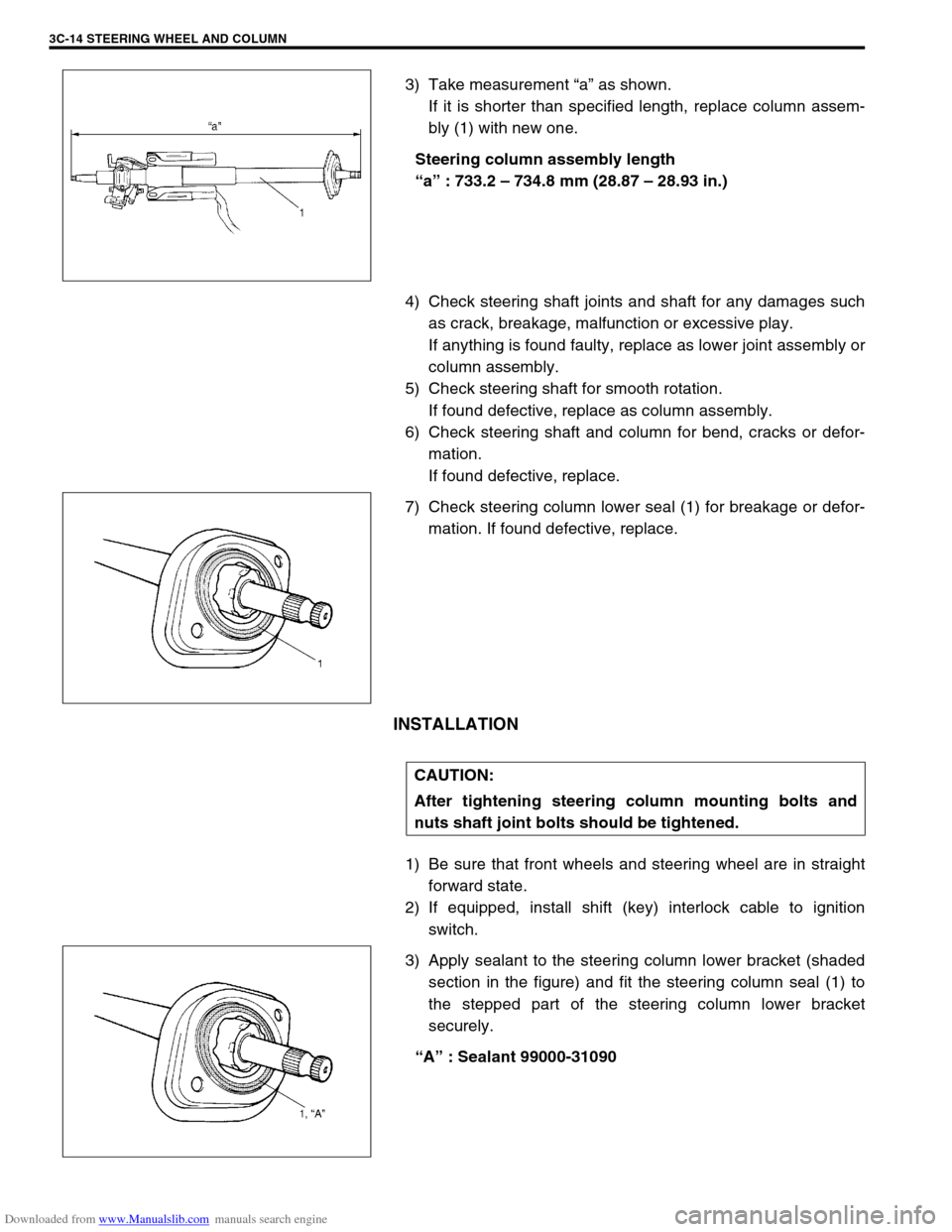
3) Take measurement “a” as shown.
If it is shorter than specified length, replace column assem-
bly (1) with new one.
Steering column assembly length
“a” : 733.2 – 734.8 mm (28.87 – 28.93 in.)
4) Check steering shaft joints and shaft for any damages such
as crack, breakage, malfunction or excessive play.
If anything is found faulty, replace as lower joint assembly or
column assembly.
5) Check steering shaft for smooth rotation.
If found defective, replace as column assembly.
6) Check steering shaft and column for bend, cracks or defor-
mation.
If found defective, replace.
7) Check steering column lower seal (1) for breakage or defor-
mation. If found defective, replace.
INSTALLATION
1) Be sure that front wheels and steering wheel are in straight
forward state.
2) If equipped, install shift (key) interlock cable to ignition
switch.
3) Apply sealant to the steering column lower bracket (shaded
section in the figure) and fit the steering column seal (1) to
the stepped part of the steering column lower bracket
securely.
“A” : Sealant 99000-31090
CAUTION:
After tightening steering column mounting bolts and
nuts shaft joint bolts should be tightened.
Page 169 of 687
Downloaded from www.Manualslib.com manuals search engine 3C-16 STEERING WHEEL AND COLUMN
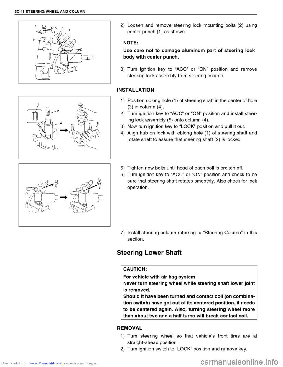
2) Loosen and remove steering lock mounting bolts (2) using
center punch (1) as shown.
3) Turn ignition key to “ACC” or “ON” position and remove
steering lock assembly from steering column.
INSTALLATION
1) Position oblong hole (1) of steering shaft in the center of hole
(3) in column (4).
2) Turn ignition key to “ACC” or “ON” position and install steer-
ing lock assembly (5) onto column (4).
3) Now turn ignition key to “LOCK” position and pull it out.
4) Align hub on lock with oblong hole (1) of steering shaft and
rotate shaft to assure that steering shaft (2) is locked.
5) Tighten new bolts until head of each bolt is broken off.
6) Turn ignition key to “ACC” or “ON” position and check to be
sure that steering shaft rotates smoothly. Also check for lock
operation.
7) Install steering column referring to “Steering Column” in this
section.
Steering Lower Shaft
REMOVAL
1) Turn steering wheel so that vehicle’s front tires are at
straight-ahead position.
2) Turn ignition switch to “LOCK” position and remove key. NOTE:
Use care not to damage aluminum part of steering lock
body with center punch.
CAUTION:
For vehicle with air bag system
Never turn steering wheel while steering shaft lower joint
is removed.
Should it have been turned and contact coil (on combina-
tion switch) have got out of its centered position, it needs
to be centered again. Also, turning steering wheel more
than about two and a half turns will break contact coil.
Page 520 of 687
Downloaded from www.Manualslib.com manuals search engine ENGINE MECHANICAL (M13 ENGINE) 6A1-39
INSTALLATION
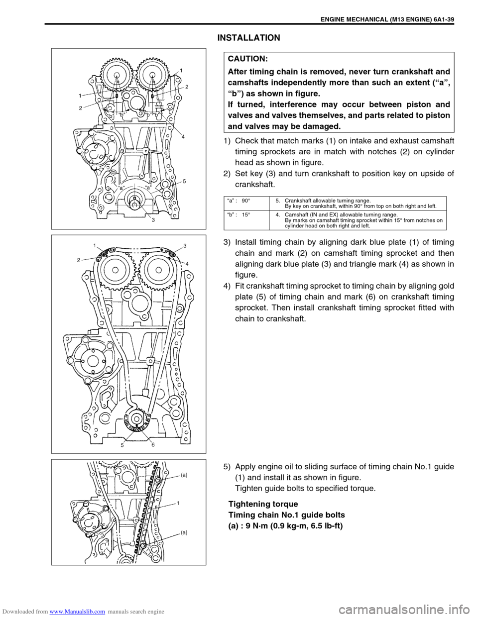
1) Check that match marks (1) on intake and exhaust camshaft
timing sprockets are in match with notches (2) on cylinder
head as shown in figure.
2) Set key (3) and turn crankshaft to position key on upside of
crankshaft.
3) Install timing chain by aligning dark blue plate (1) of timing
chain and mark (2) on camshaft timing sprocket and then
aligning dark blue plate (3) and triangle mark (4) as shown in
figure.
4) Fit crankshaft timing sprocket to timing chain by aligning gold
plate (5) of timing chain and mark (6) on crankshaft timing
sprocket. Then install crankshaft timing sprocket fitted with
chain to crankshaft.
5) Apply engine oil to sliding surface of timing chain No.1 guide
(1) and install it as shown in figure.
Tighten guide bolts to specified torque.
Tightening torque
Timing chain No.1 guide bolts
(a) : 9 N·m (0.9 kg-m, 6.5 lb-ft) CAUTION:
After timing chain is removed, never turn crankshaft and
camshafts independently more than such an extent (“a”,
“b”) as shown in figure.
If turned, interference may occur between piston and
valves and valves themselves, and parts related to piston
and valves may be damaged.
“a” :90°5. Crankshaft allowable turning range.
By key on crankshaft, within 90° from top on both right and left.
“b” :15°4. Camshaft (IN and EX) allowable turning range.
By marks on camshaft timing sprocket within 15° from notches on
cylinder head on both right and left.
Page 522 of 687
Downloaded from www.Manualslib.com manuals search engine ENGINE MECHANICAL (M13 ENGINE) 6A1-41
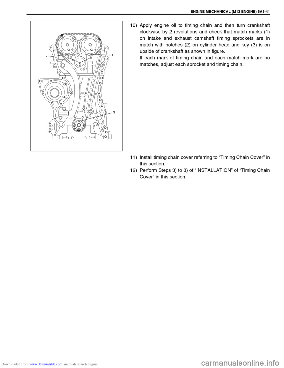
10) Apply engine oil to timing chain and then turn crankshaft
clockwise by 2 revolutions and check that match marks (1)
on intake and exhaust camshaft timing sprockets are in
match with notches (2) on cylinder head and key (3) is on
upside of crankshaft as shown in figure.
If each mark of timing chain and each match mark are no
matches, adjust each sprocket and timing chain.
11) Install timing chain cover referring to “Timing Chain Cover” in
this section.
12) Perform Steps 3) to 8) of “INSTALLATION” of “Timing Chain
Cover” in this section.
21
1
3
Page 527 of 687
Downloaded from www.Manualslib.com manuals search engine 6A1-46 ENGINE MECHANICAL (M13 ENGINE)
INSTALLATION
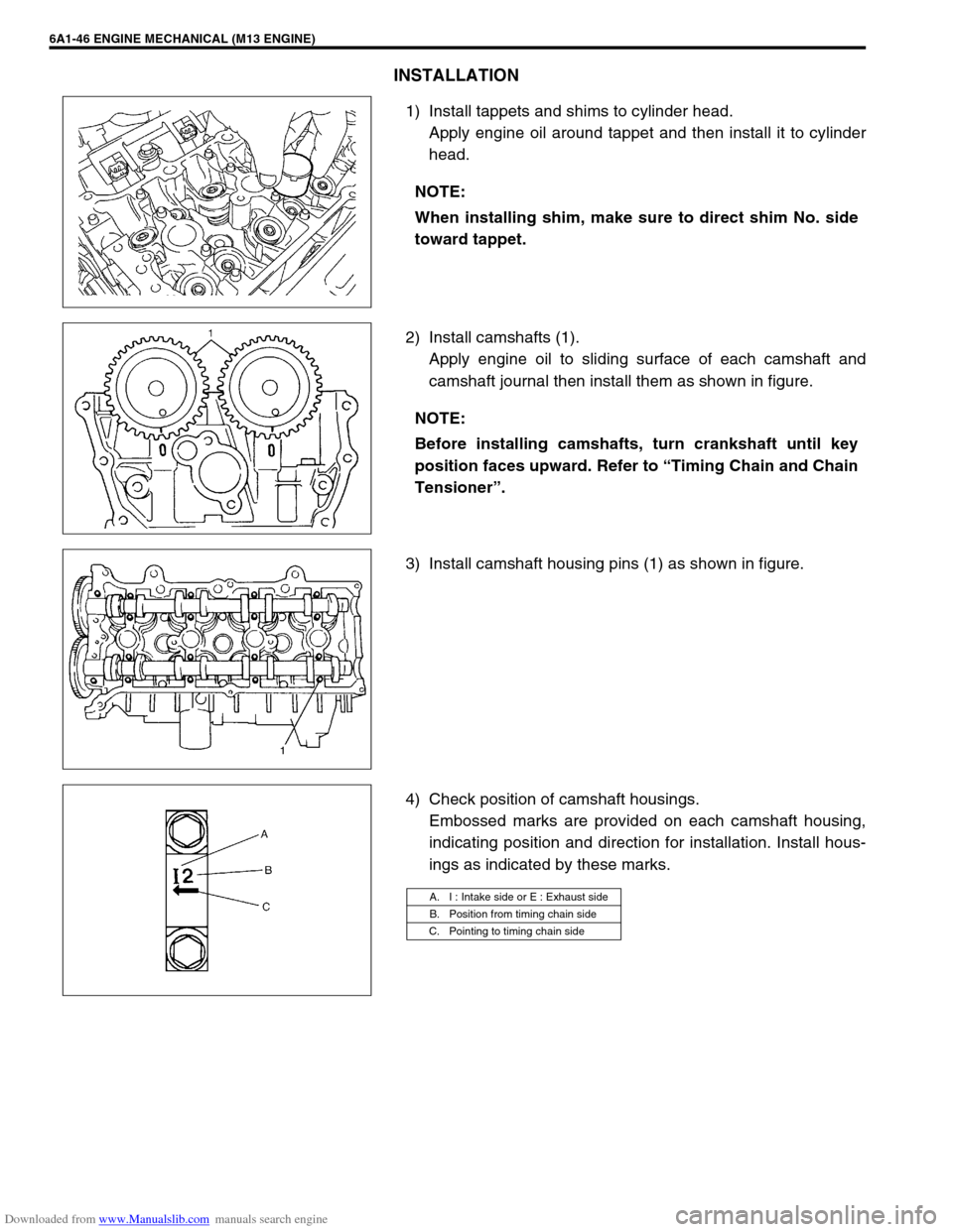
1) Install tappets and shims to cylinder head.
Apply engine oil around tappet and then install it to cylinder
head.
2) Install camshafts (1).
Apply engine oil to sliding surface of each camshaft and
camshaft journal then install them as shown in figure.
3) Install camshaft housing pins (1) as shown in figure.
4) Check position of camshaft housings.
Embossed marks are provided on each camshaft housing,
indicating position and direction for installation. Install hous-
ings as indicated by these marks. NOTE:
When installing shim, make sure to direct shim No. side
toward tappet.
NOTE:
Before installing camshafts, turn crankshaft until key
position faces upward. Refer to “Timing Chain and Chain
Tensioner”.
A. I : Intake side or E : Exhaust side
B. Position from timing chain side
C. Pointing to timing chain side
Page 560 of 687
Downloaded from www.Manualslib.com manuals search engine ENGINE MECHANICAL (M13 ENGINE) 6A1-79
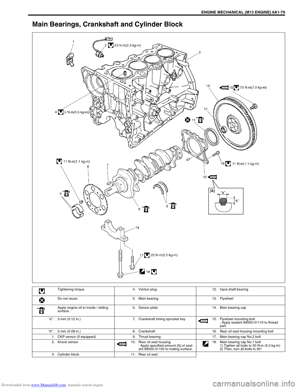
Main Bearings, Crankshaft and Cylinder Block
Tightening torque 4. Venturi plug 12. Input shaft bearing
Do not reuse. 5. Main bearing 13. Flywheel
Apply engine oil to inside / sliding
surface.6. Sensor plate 14. Main bearing cap
“a” : 3 mm (0.12 in.) 7. Crankshaft timing sprocket key 15. Flywheel mounting bolt
: Apply sealant 99000-31110 to thread
part.
“b” : 2 mm (0.08 in.) 8. Crankshaft 16. Rear oil seal housing mounting bolt
1. CKP sensor (if equipped) 9. Thrust bearing 17. Main bearing cap No.2 bolt
2. Knock sensor 10. Rear oil seal housing
: Apply specified amount [A] of seal-
ant 99000-31150 to mating surface. 18. Main bearing cap No.1 bolt
1) Tighten all bolts to 50 N·m (5.0 kg-m)
2) Then, turn all bolts to 60°
3. Cylinder block 11. Rear oil seal