piston bolts SUZUKI JIMNY 2005 3.G Service Workshop Manual
[x] Cancel search | Manufacturer: SUZUKI, Model Year: 2005, Model line: JIMNY, Model: SUZUKI JIMNY 2005 3.GPages: 687, PDF Size: 13.38 MB
Page 68 of 687

Downloaded from www.Manualslib.com manuals search engine AIR CONDITIONING (OPTIONAL) 1B-7
Abnormal Noise Diagnosis
There are various types of noise, ranging from those produced in the engine compartment to those from the
passenger compartment, also from rumbling noises to whistling noises.
Abnormal noise from compressor
Abnormal noise from magnetic clutch
Abnormal noise from tubing
Abnormal noise from condenser
Condition Possible Cause Correction
During compressor
operation, a rumbling
noise is heard propor-
tional to engine revo-
lutions.Inadequate clearance in piston area (piston or
swash-plate).Repair or replace compressor as
necessary
A loud noise is heard
at a certain rpm, dis-
proportionately to
engine revolution.Loose or faulty compressor drive belt. Adjust drive belt tension, or replace
belt.
Loose compressor mounting bolts. Retighten mounting bolts.
A loud rattle is heard
at low engine rpm.Loose compressor clutch plate bolt. Retighten clutch plate bolt.
Replace compressor if it was oper-
ated in this condition for a long
time.
Condition Possible Cause Correction
A rumbling noise is
heard when compres-
sor is not operating.Worn or damaged bearings. Replace magnet clutch assembly.
A chattering noise is
heard when compres-
sor is engaged.Faulty clutch clearance (excessive). Adjust clutch clearance.
Worn clutch friction surface. Replace magnet clutch assembly.
Compressor oil leaked from lip type seal. Replace lip type seal.
Contaminating the friction surface. Replace compressor body assem-
bly.
Condition Possible Cause Correction
A droning noise is
heard inside vehicle,
but not particularly
noticeable in engine
compartment.Faulty tubing clamps. Reposition clamps or increase the
number of clamps.
Resonance caused by pulsation from variations
in refrigerant pressure.Attach a silencer to tubing, or mod-
ify its position and length.
Condition Possible Cause Correction
Considerable vibra-
tion in condenser.Resonance from condenser bracket and body. Firmly insert a silencer between
condenser bracket and body.
Page 266 of 687

Downloaded from www.Manualslib.com manuals search engine BRAKES 5-5
Diagnosis Table
Condition Possible Cause Correction
Not enough braking
forceBrake oil leakage from brake lines Locate leaking point and repair.
Brake disc or pads stained with oil Clean or replace.
Overheated brakes Determine cause and repair.
Poor contact of shoes on brake drum Repair for proper contact.
Brake shoes linings stained with oil or wet with
waterReplace.
Badly worn brake shoe linings Replace.
Defective wheel cylinders Repair or replace.
Malfunctioning caliper assembly Repair or replace.
Air in system Bleed system.
Maladjusted sensor spring length of LSPV Check or adjust.
Broken sensor spring of LSPV Replace.
Defective collar of LSPV Replace.
Malfunctioning ABS (Antilock brake system), if
equippedCheck system and replace as nec-
essary.
Brake pull (Brakes not
working in unison)Pad or shoe linings are wet with water or
stained with oil in some brakesReplace.
Drum-to-shoe clearance out of adjustment in
some brakes (Malfunctioning auto adjusting
mechanism)Check for inoperative auto adjusting
mechanism.
Drum is out of round in some brakes Replace.
Wheel tires are inflated unequally Inflate equally.
Malfunctioning wheel cylinders Repair or replace.
Disturbed front wheel alignment Adjust as prescribed.
Unmatched tires on same axle Tires with approximately the same
amount of tread should be used on
the same axle.
Restricted brake tubes or hoses Check for soft hoses and damaged
lines.
Replace with new hoses and new
double-walled steel brake tubing.
Malfunctioning caliper assembly Check for stuck or sluggish pistons
and proper lubrication of caliper
slide bush.
Loose suspension parts Caliper should slide.
Check all suspension mountings.
Loose calipers Check and torque bolts to specifica-
tions.
Noise (high pitched
squeak without brake
applied)Front lining worn out Replace brake pads.
Rear brake locked pre-
maturelyMaladjusted sensor spring length of LSPV Check or adjust.
Malfunctioning LSPV assembly Replace assembly.
Brake locked
(For vehicles
equipped with ABS)Malfunctioning ABS, if equipped Check system and replace as nec-
essary.
Page 267 of 687

Downloaded from www.Manualslib.com manuals search engine 5-6 BRAKES
Excessive pedal travel
(Pedal stroke too
large)Partial brake system failure Check brake systems and repair as
necessary.
Insufficient fluid in master cylinder reservoirs Fill reservoirs with approved brake
fluid.
Check for leaks and air in brake
systems.
Check warning light. Bleed system
if required.
Air in system (pedal soft/spongy) Bleed system.
Rear brake system not adjusted (malfunctioning
auto adjusting mechanism)Repair auto adjusting mechanism.
Adjust rear brakes.
Bent brake shoes Replace brake shoes.
Worn rear brake shoes Replace brake shoes.
Dragging brakes (A
very light drag is
present in all disc
brakes immediately
after pedal is released)Master cylinder pistons not returning correctly Repair master cylinder.
Restricted brake tubes or hoses Check for soft hoses or damaged
tubes and replace with new hoses
and/or new brake tubes.
Incorrect parking brake adjustment on rear
brakesCheck and adjust to correct specifi-
cations.
Weakened or broken return springs in the brake Replace.
Sluggish parking-brake cables or linkage Repair or replace.
Wheel cylinder or caliper piston sticking Repair as necessary.
Malfunctioning ABS, if equipped with ABS Check system and replace as nec-
essary.
Pedal pulsation (Pedal
pulsates when
depressed for brak-
ing.) Damaged or loose wheel bearings Replace wheel bearings.
Distorted steering knuckle or rear axle shafts Replace knuckle or rear axle shaft.
Excessive disc lateral runout Check per instructions. If not within
specifications, replace or machine
the disc.
Parallelism not within specifications Check per instructions. If not with
specifications, replace or machine
the disc.
Rear drums out of round. Check runout.
Repair or replace drum as neces-
sary.
Braking noise
Glazed shoe linings, or foreign matters stuck to
liningsRepair or replace brake shoe.
Worn or distorted shoe linings Replace brake shoe (or pad).
Loose front wheel bearings Replace wheel bearing.
Distorted backing plates or loose mounting
boltsReplace or retighten securing bolts.
Brake warning light
turns on after engine
startParking brake applied Release parking brake and check
that brake warning light turns off.
Insufficient amount of brake fluid Add brake fluid.
Brake fluid leaking from brake line Investigate leaky point, correct it
and add brake fluid.
Brake warning light circuit faulty Repair circuit. Condition Possible Cause Correction
Page 283 of 687
Downloaded from www.Manualslib.com manuals search engine 5-22 BRAKES
Caliper assembly
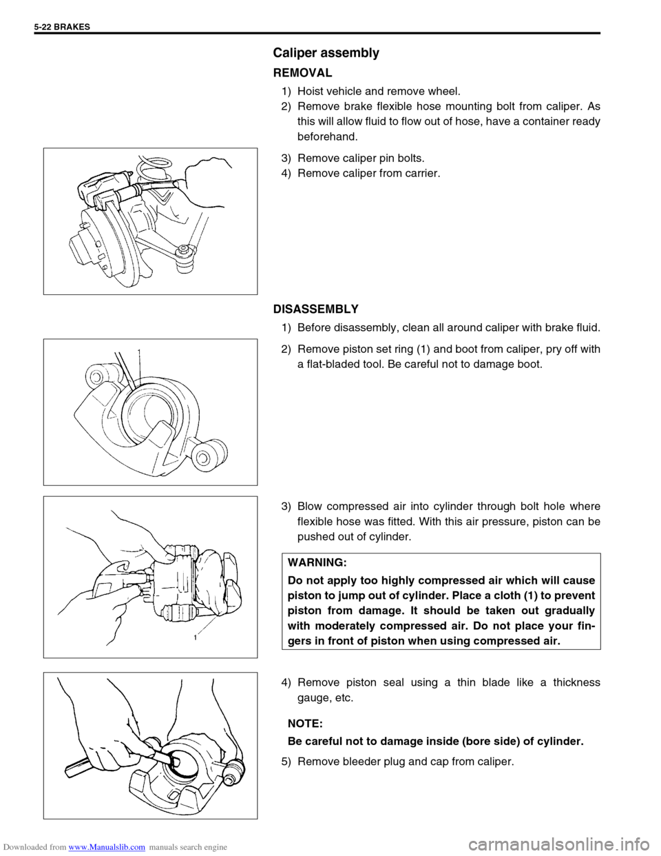
REMOVAL
1) Hoist vehicle and remove wheel.
2) Remove brake flexible hose mounting bolt from caliper. As
this will allow fluid to flow out of hose, have a container ready
beforehand.
3) Remove caliper pin bolts.
4) Remove caliper from carrier.
DISASSEMBLY
1) Before disassembly, clean all around caliper with brake fluid.
2) Remove piston set ring (1) and boot from caliper, pry off with
a flat-bladed tool. Be careful not to damage boot.
3) Blow compressed air into cylinder through bolt hole where
flexible hose was fitted. With this air pressure, piston can be
pushed out of cylinder.
4) Remove piston seal using a thin blade like a thickness
gauge, etc.
5) Remove bleeder plug and cap from caliper.
WARNING:
Do not apply too highly compressed air which will cause
piston to jump out of cylinder. Place a cloth (1) to prevent
piston from damage. It should be taken out gradually
with moderately compressed air. Do not place your fin-
gers in front of piston when using compressed air.
NOTE:
Be careful not to damage inside (bore side) of cylinder.
Page 286 of 687
Downloaded from www.Manualslib.com manuals search engine BRAKES 5-25
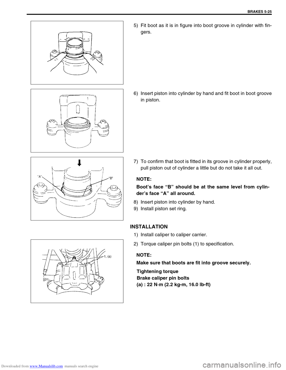
5) Fit boot as it is in figure into boot groove in cylinder with fin-
gers.
6) Insert piston into cylinder by hand and fit boot in boot groove
in piston.
7) To confirm that boot is fitted in its groove in cylinder properly,
pull piston out of cylinder a little but do not take it all out.
8) Insert piston into cylinder by hand.
9) Install piston set ring.
INSTALLATION
1) Install caliper to caliper carrier.
2) Torque caliper pin bolts (1) to specification.
Tightening torque
Brake caliper pin bolts
(a) : 22 N·m (2.2 kg-m, 16.0 lb-ft)
NOTE:
Boot’s face “B” should be at the same level from cylin-
der’s face “A” all around.
NOTE:
Make sure that boots are fit into groove securely.
Page 383 of 687

Downloaded from www.Manualslib.com manuals search engine 6-26 ENGINE GENERAL INFORMATION AND DIAGNOSIS
Excessive engine oil
consumptionSticky piston ring Pistons, piston rings, connecting rods
and cylinders in Section 6A1.
Worn piston and cylinder Pistons, piston rings, connecting rods
and cylinders in Section 6A1.
Worn piston ring groove and ring Pistons, piston rings, connecting rods
and cylinders in Section 6A1.
Improper location of piston ring gap Pistons, piston rings, connecting rods
and cylinders in Section 6A1.
Worn or damaged valve stem seal Valves and cylinder head in Section
6A1.
Worn valve stem Valves and cylinder head in Section
6A1.
Low oil pressure
Improper oil viscosity ITEM1-3 Engine oil and oil filter
change in Section 0B.
Malfunctioning oil pressure switch Oil pressure switch in Section 8.
Clogged oil strainer Oil pan and oil pump strainer in Sec-
tion 6A1.
Functional deterioration of oil pump Oil pump in Section 6A1.
Worn oil pump relief valve Oil pump in Section 6A1.
Excessive clearance in various sliding
partsRefer to Section 6A1.
Engine noise
See NOTE below.Improper valve lash Valve lash in Section 6A1.
Worn valve stem and guide Valves and cylinder head in Section
6A1.
Weak or broken valve spring Valve springs in Section 6A1.
Warped or bent valve Valves and cylinder head in Section
6A1.
Loose camshaft housing bolts Camshaft in Section 6A1.
Worn piston, ring and cylinder bore Pistons and cylinders in Section 6A1.
Worn crankpin bearing Crankpin and connecting rod bearing
in Section 6A1.
Worn crankpin Crankpin and connecting rod bearing
in Section 6A1.
Loose connecting rod nuts Connecting rod in Section 6A1.
Low oil pressure Previously outlined.
Worn crankshaft journal bearing Main bearings, Crankshaft and cylin-
der block in Section 6A1.
Worn crankshaft journal Main bearings, Crankshaft and cylin-
der block in Section 6A1.
Loose lower crankcase (bearing cap) bolts Main bearings, Crankshaft and cylin-
der block in Section 6A1.
Excessive crankshaft thrust play Main bearings, Crankshaft and cylin-
der block in Section 6A1. Condition Possible Cause Reference Item
NOTE:
Before checking the mechanical noise, make sure that :
Ignition timing is properly adjusted.
Specified spark plug is used.
Specified fuel is used.
Page 520 of 687
Downloaded from www.Manualslib.com manuals search engine ENGINE MECHANICAL (M13 ENGINE) 6A1-39
INSTALLATION
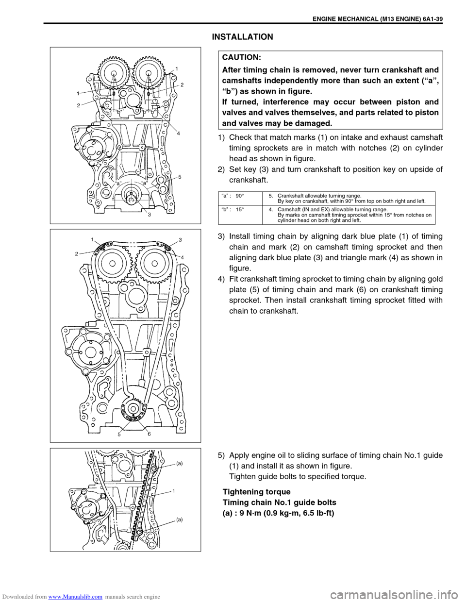
1) Check that match marks (1) on intake and exhaust camshaft
timing sprockets are in match with notches (2) on cylinder
head as shown in figure.
2) Set key (3) and turn crankshaft to position key on upside of
crankshaft.
3) Install timing chain by aligning dark blue plate (1) of timing
chain and mark (2) on camshaft timing sprocket and then
aligning dark blue plate (3) and triangle mark (4) as shown in
figure.
4) Fit crankshaft timing sprocket to timing chain by aligning gold
plate (5) of timing chain and mark (6) on crankshaft timing
sprocket. Then install crankshaft timing sprocket fitted with
chain to crankshaft.
5) Apply engine oil to sliding surface of timing chain No.1 guide
(1) and install it as shown in figure.
Tighten guide bolts to specified torque.
Tightening torque
Timing chain No.1 guide bolts
(a) : 9 N·m (0.9 kg-m, 6.5 lb-ft) CAUTION:
After timing chain is removed, never turn crankshaft and
camshafts independently more than such an extent (“a”,
“b”) as shown in figure.
If turned, interference may occur between piston and
valves and valves themselves, and parts related to piston
and valves may be damaged.
“a” :90°5. Crankshaft allowable turning range.
By key on crankshaft, within 90° from top on both right and left.
“b” :15°4. Camshaft (IN and EX) allowable turning range.
By marks on camshaft timing sprocket within 15° from notches on
cylinder head on both right and left.
Page 543 of 687
Downloaded from www.Manualslib.com manuals search engine 6A1-62 ENGINE MECHANICAL (M13 ENGINE)
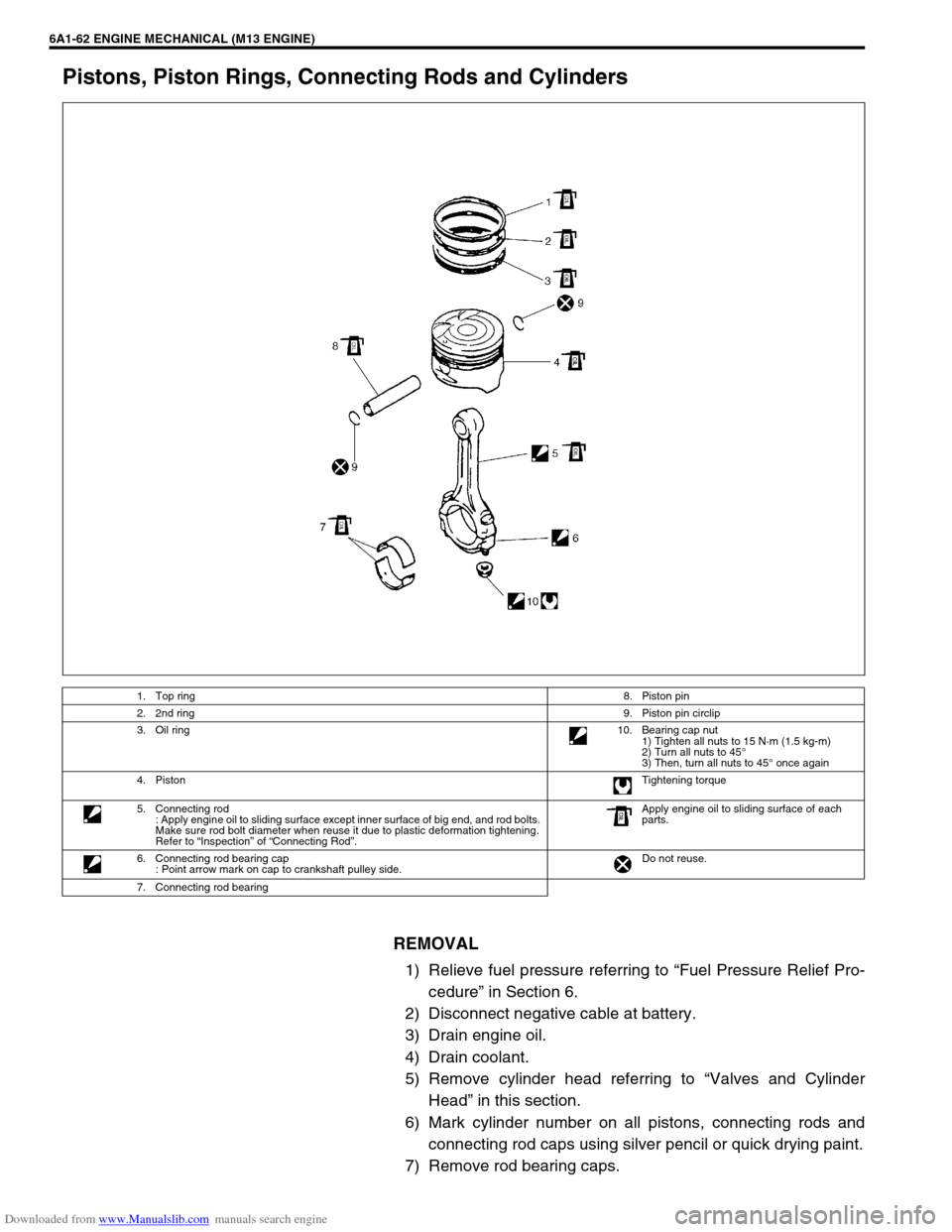
Pistons, Piston Rings, Connecting Rods and Cylinders
REMOVAL
1) Relieve fuel pressure referring to “Fuel Pressure Relief Pro-
cedure” in Section 6.
2) Disconnect negative cable at battery.
3) Drain engine oil.
4) Drain coolant.
5) Remove cylinder head referring to “Valves and Cylinder
Head” in this section.
6) Mark cylinder number on all pistons, connecting rods and
connecting rod caps using silver pencil or quick drying paint.
7) Remove rod bearing caps.
1. Top ring8. Piston pin
2. 2nd ring9. Piston pin circlip
3. Oil ring10. Bearing cap nut
1) Tighten all nuts to 15 N·m (1.5 kg-m)
2) Turn all nuts to 45°
3) Then, turn all nuts to 45° once again
4. PistonTightening torque
5. Connecting rod
: Apply engine oil to sliding surface except inner surface of big end, and rod bolts.
Make sure rod bolt diameter when reuse it due to plastic deformation tightening.
Refer to “Inspection” of “Connecting Rod”.Apply engine oil to sliding surface of each
parts.
6. Connecting rod bearing cap
: Point arrow mark on cap to crankshaft pulley side.Do not reuse.
7. Connecting rod bearing
Page 544 of 687
Downloaded from www.Manualslib.com manuals search engine ENGINE MECHANICAL (M13 ENGINE) 6A1-63
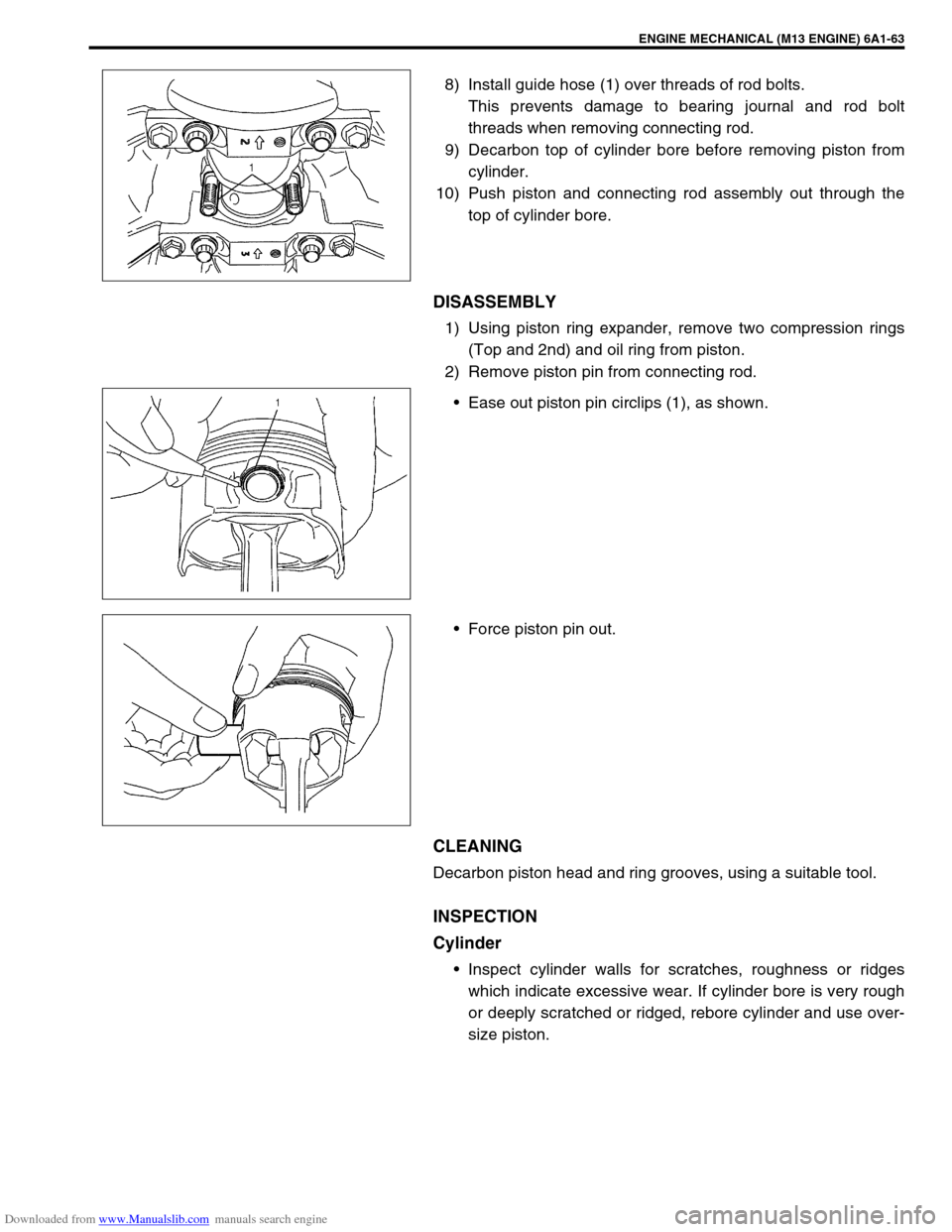
8) Install guide hose (1) over threads of rod bolts.
This prevents damage to bearing journal and rod bolt
threads when removing connecting rod.
9) Decarbon top of cylinder bore before removing piston from
cylinder.
10) Push piston and connecting rod assembly out through the
top of cylinder bore.
DISASSEMBLY
1) Using piston ring expander, remove two compression rings
(Top and 2nd) and oil ring from piston.
2) Remove piston pin from connecting rod.
Ease out piston pin circlips (1), as shown.
Force piston pin out.
CLEANING
Decarbon piston head and ring grooves, using a suitable tool.
INSPECTION
Cylinder
Inspect cylinder walls for scratches, roughness or ridges
which indicate excessive wear. If cylinder bore is very rough
or deeply scratched or ridged, rebore cylinder and use over-
size piston.
Page 551 of 687

Downloaded from www.Manualslib.com manuals search engine 6A1-70 ENGINE MECHANICAL (M13 ENGINE)
INSTALLATION
1) Apply engine oil to pistons, rings, cylinder walls, connecting
rod bearings and crankpins.
2) Install guide hoses (1) over connecting rod bolts.
These guide hoses protect crank pin and threads of rod bolt
from damage during installation of connecting rod and piston
assembly.
3) When installing piston and connecting rod assembly into cyl-
inder bore, point front mark on piston head to crankshaft pul-
ley side.
4) Install piston and connecting rod assembly into cylinder
bore. Use special tool (Piston ring compressor) to compress
rings. Guide connecting rod into place on crankshaft.
Using a hammer handle, tap piston head to install piston into
bore. Hold ring compressor firmly against cylinder block until
all piston rings have entered cylinder bore.
Special tool
(A) : 09916-77310 NOTE:
Do not apply oil between connecting rod and bearing or
between bearing cap and bearing.
A : Crankshaft pulley side
B : Flywheel side